1
Data Sheet 039 Rev 3
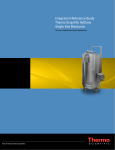
A vent filter heater system is an
additional option for the Thermo
Scientific HyClone Single-Use
Bioreactor (S.U.B.) system. It is
supplied as an accessory for
those customers who require it
to protect the vent filter on the
standard S.U.B. BPC®.
Thermo Scientific HyClone
Single-Use Bioreactor
Vent Filter Heater
Overview:
The resistive heating element is fully insulated with
molded silicone foam and is easily secured around
the filter by use of two snap retainers. This custom
molded heater creates a perfect fit that will fully
encapsulate the exhaust filters for consistent
temperature regulation. The temperature controller is
preset specifically for the HyClone Single-Use
Bioreactor (S.U.B.) at 50°C and has an adjustable
temperature range of 0-220°C. Temperatures above
60°C are not recommended for the filters used on
the S.U.B. The controller has programmable logic
and is equipped with a low temperature alarm
output. The vent filter heater system stands alone
and does not integrate with the control system of
the S.U.B. controller. The system consists of the
following components: Heater, Controller and
Power Cord. Refer to the vent filter user’s manual
included.
2. Attach connector to controller
3. Attach controller to electrical supply
System Components and use:
1. Place heater over filter
Vent Filter in
S.U.B. BPC
MKS Controller
Heater
Power Cord
Ordering Information
Part Number
Description
Additional Information
SV50191.01
Vent Filter Heater with Programmable Controller (100-120 VAC)
Includes low temp alarm. Preset temperature 50°C
SV50191.02
Power Cord (100-120 VAC)
For use in U.S./Japan, NEMA 5-15P with 12’ leads
SV50191.03
Vent Filter Heater with Programmable Controller (200-240 VAC)
Includes low temp alarm. Preset temperature 50°C
SV50191.04
Power Cord (240 VAC)
For use in United Kingdom, BS1363 with 10’ leads
SV50191.05
Power Cord (240 VAC)
For use in Europe, CEE7/7 with 12’ leads
SV50191.06
Power Cord (100-120 VAC)
For use in U.S./Japan, NEMA 5-15P with 12’ leads and GFCI
SV50191.07
Power Cord (240 VAC)
For use in United Kingdom, BS1363 with 12’ leads and GFCI
SV50191.08
Power Cord (240 VAC)
For use in Europe, CEE 7/7 with 12’ leads and GFCI
SV50191.09
Extension Cord for Series 48 Heater (100-240 VAC)
For use between heater and controller, 10’
SV50191.10
Vent Filter Heater with RTD (two wire Pt-100), (100-120 VAC/17-24 W) Includes sheathed 20’ pig-tail lead
Data Sheet
©2008 Thermo Fisher Scientific Inc. All rights reserved. All trademarks are the property of Thermo Fisher Scientific Inc. and its subsidiaries. Specifications, terms
and pricing are subject to change. Not all products are available in all countries. Please consult your local sales representative for details.
46456
HyClone - Media•BPC•Sera
925 West 1800 South
Logan, UT
84321
In Americas/Asia
435-792-8000
435-792-8001 fax
In Europe
+32 53 85 75 59
+32 53 85 74 31 fax
www.thermo.com/hyclone
HyClone Laboratories, Inc. Logan, UT USA is ISO Certified.
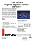
Series 48
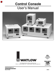
Integrated Temperature Controller
User’s Manual
For more information or literature, contact:
MKS Instruments, Inc.
5330 Sterling Drive
Boulder, CO 80301 USA
Phone:
Toll Free:
Fax:
Email:
Web:
1-303-449-9861
1-800-345-1967
1-303-442-6880
[email protected]
www.mksinst.com/hpshome.html
© 2006 by MKS Instruments, Inc. All rights reserved.
Table of Contents
Table of Contents ............................................................................................................ 3
Introduction ..................................................................................................................... 4
Features & Benefits......................................................................................................... 5
Specification & Dimensions............................................................................................. 6
Dimensions.................................................................................................................. 6
Safety Agency Testing................................................................................................. 6
Navigating the Front Panel.............................................................................................. 7
Keys and Indicator Lights ............................................................................................. 8-9
Proportional Control ...................................................................................................... 10
Proportional Plus Integral (PI) Control ....................................................................... 10
Proportional Plus Integral Plus Derivative (PID) Control............................................ 10
Mounting the Series 48 Controller ................................................................................. 11
Panel Mount Dimensions........................................................................................... 12
Mounting Bracket....................................................................................................... 12
Wiring the Series 48 Controller ..................................................................................... 13
Power and relay connector ........................................................................................ 13
Thermocouple and heater connector ......................................................................... 13
Ordering Information ..................................................................................................... 14
Introduction
The Series 48 Temperature Controller is a powerful instrument that integrates a temperature process
controller, high-low temperature alert, and power switching with a safety high limit that meets UL® 1998
and CE 60730 requirements. The optional display and communications modules can be easily upgraded
in the field to provide a digital display, adjustable control parameters, RS485 MODBUS communications
and other interface features. The compact design, inherent reliability and integrated safety limit functions
make this controller a tremendous value. The controller is designed for easy integration with HPS heaters
providing additional value to simplify the engineering and component count on new equipment. CE
compliance and UL recognition will reduce time and costs necessary for global agency testing and
validation for OEMs.
Features & Benefits
Standard Base Module
•
•
•
•
•
•
•
•
•
•
Re-settable high temperature safety limit device, eliminates thermal fuse and allows for easy
reset after an over temperature event
Redundant limit circuitry with dedicated TC and limit relay
Limit relay is latching and can be reset by cycling power
Low Temperature Alert / High Temperature Alert (LTA/HTA) integrated into control circuitry
Dedicated mechanical relay output for LTA/HTA
LED for local LTA/HTA alarm indication
Set points for both LTA and HTA are field programmable
Modular Communication and HMI Module
Separate plug-in module adapts to Base Control Unit
Can be retrofit in field at any time
Provides capability to display temperature, and adjust set point
Also provides capability to add serial communications
3 LEDs included to provide (1) Load Light, (2) HTA/LTA indication, (3) High Limit indication and
general alarms
Backwards compatible with Series 46 and Series 45
Plug and play heater installation
UL/C-UL Listed, CE, Semi S2
Optional Communications Module
•
•
•
•
•
•
Field adjustable set point
Access to PID parameters
Modbus RTU Communications
RS485 Interface
3-character, 7-segment LED display
User Interface Software
Specification & Dimensions
•
•
•
•
•
•
•
•
•
•
•
(2) Type K Thermocouple Inputs: Process Temperature Controller and Safety Limit.
Isolated Universal Power Supply: 100 to 240VÅ (ac) 50/60Hz
Ambient operating temperature range 0 to 70°C
Process Temperature Output: 10 amp “No Arc” relay
Safety Limit: 10 amp relay
High-Low Temperature Alert: 2 amp, 30Vı (ac/dc), Form A relay
On-Off and PID temperature control algorithm. Upgraded via communications to PID algorithm
(minimum cycle time 5 seconds).
Control Method: On/Off control mode, 3 Deg C hysteresis. PID control mode available with HMI
Module. Receives set-point through display module, or communication link and stored in
nonvolatile memory
Address Assignment: via set up menu through keypad or software interface.
Three LED’s: Green (output action), Yellow (in range) Red (fault)
Temperature Range: 0-220°C
Power
•
•
•
•
Input Power: 85 - 264 VAC
Control Output : Mechanical Relay, 277VAC Max, 50-60hz, 10.0A max
Safety Limit Output: Mechanical Relay, 277VAC Max, 50-60hz, 10.0A max
LTA/HTA Output: Mechanical Relay, 30 VDC Max, 2.0A Max
Environment
•
•
•
•
•
•
Indoor use only
Maximum Storage Temperature: 185°F (85°C)
Minimum Storage Temperature: 0°F (-18°C)
Maximum Operating Temperature: 158°F (70°C)
Minimum Operating Temperature: 32°F (0°C)
Relative Humidity: 5-95% (non condensing)
Dimensions
Configuration
Width
Depth
Height
Basic Unit
88.8 mm
(3.496 in)
40.2 mm
(1.582 in)
55.8 mm
(2.196 in)
With Mounting Bracket
88.8 mm
(3.496 in)
48.4 mm
(1.907 in)
55.8 mm
(2.196 in)
With communications display
modules & mounting bracket
88.8 mm
(3.496 in)
63.6 mm
(2.503)
55.8 mm
(2.196 in)
Safety Agency Testing
•
UL/C-UL Listed, CE, Semi S2
Navigating the Front Panel
The three-character display normally shows the process temperature. Press the Mode Key once to view
the Set Point value. The right decimal point will illuminate when viewing the Set Point value. Press the
Up-Arrow or Down-Arrow Key to change the Set Point. Press the Mode Key again to return to the process
temperature display. Otherwise the display will automatically return to showing the process temperature
after three seconds.
To view or change parameter values, hold down both the Up-Arrow and Down-Arrow Keys for three
seconds. This will display the Set Point High Limit prompt. Press the Mode Key to view the other
parameter prompts. Press the Up-Arrow or Down-Arrow Key once to view a parameter’s value. Press the
Up-Arrow or Down-Arrow Key to increase or decrease that value. Press the Mode Key to again display
the prompt and again to display the next prompt. Press the Mode Key at the Prototype Version prompt to
return to the process value display.
Keys and Indicator Lights
Keys and Indicator Lights (cont.)
Proportional Control
Some processes need to maintain a temperature or process value closer to the set point than on-off
control can provide. Proportional control provides closer control by adjusting the output when the
temperature or process value is within a proportional band. When the value is in the band, the controller
adjusts the output based on how close the process value is to the set point. The closer the process value
is to the set point, the lower the output
power. This is similar to backing off on the
gas pedal of a car as you approach a stop
sign. It keeps the temperature or process
value from swinging as widely as it would
with simple on-off control. However, when
the system settles down, the temperature or
process value tends to “droop” short of the
set point. With proportional control the
output power level equals (set point minus
process value) divided by the proportional
band value.
Adjust the proportional band with
Proportional [`Pb;]
Proportional Plus Integral (PI) Control
The droop caused by proportional control can be corrected by adding integral control. When the system
settles down, the integral value is tuned to bring the temperature or process value closer to the set point.
Integral determines the speed of the correction, but this may increase the overshoot at startup or when
the set point is changed. Too much integral action will make the system unstable. Integral is cleared when
the process value is outside of the proportional band.
Integral [Int] is measured in minutes per repeat. A low integral value causes a fast integrating action.
Proportional Plus Integral Plus
Derivative (PID) Control
Use derivative control to minimize the
overshoot in a PI-controlled system.
Derivative [dE;u] adjusts the output based
on the rate of change in the temperature or
process value. Too much derivative will
make the system sluggish.
Mounting the Series 48 Controller
Mounting the Series 48 Controller
Panel Mount Dimensions
Mounting Bracket
The Series EHG SL 10 mounting bracket lets you mount the
controller in any of four angles. After disconnecting both wiring
connectors, gently rotate the controller counterclockwise until it
unlocks from the mounting bracket. Re-orient the controller on
the mounting bracket and gently rotate it clockwise until it locks.
Wiring the Series 48 Controller
Power and relay connector
Thermocouple and heater connector
Ordering Information