Transcript
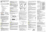
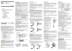
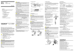
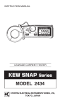
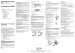
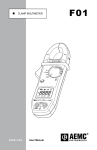
CL340 Leakage Clamp-on Tester IM CL340 WARNING Correct Wrong Over-voltage category I (CAT.I): Signal level, special equipment or parts of equipment, telecommunication, electronic etc., with smaller transient over-voltages than CAT.II. Load Over-voltage category II (CAT.II) Local level, appliance, portable equipment etc., with smaller transient over-voltages than CAT.III. Over-voltage category III (CAT.III): 3. Other Functions 4. Battery Replacement ● Be sure to set the Range switch to the "OFF" position after use. When the instrument will not be in use for a long period of time, Place it in storage after removing the battery. ● Use a damp cloth and detergent for cleaning the instrument. Do not use abrasives or solvents. 5. Specifications 6. Calibration and After-sales Service 99 Washington Street Melrose, MA 02176 Fax 781-665-0780 TestEquipmentDepot.com IM CL340 2nd Edition: June 2003 (MC) NOTE ● Radiation immunity affects the accuracy of CL340 testers under the conditions specified in EN 61000-4-3:1997. ● If equipment generating strong electromagnetic interference is located nearly, the testers may malfunction. 1. Instrument Layout Open/Close Lever Range Selector Switch Transformer Jaws The instrument and this manual use the following safety symbols: Danger! Handle with Care. This symbol indicates that the operator must refer to an explanation in the User’s Manual in order to avoid the risk of personal injury or death and/or damage to the instrument. Double Insulation This symbol indicates double insulation. Frequency Selector Button Peak Hold Button Display Data Hold Button LCD Low Battery Warning Data Hold Indication Frequency Response [WIDE] Peak Hold Indication Frequency Response [50/60Hz] Unit of measured quantity AC Voltage/Current This symbol indicates AC voltage or current. This symbol indicates ground (earth) WARNING Indicates that there is a possibility of serious personal injury or loss of life if the operating procedure is not followed correctly and describes the precautions for avoiding such injury or loss of life. CAUTION Indicates that there is a possibility of serious personal injury of damage to the instrument if the operating procedure is not followed correctly and describes the precautions for avoiding such injury or damage. NOTE Draws attention to information essential for understanding the operation and features. WARNING ● Never make measurement on a circuit above 300V AC. ● Do not use the instrument in an atmosphere where any flammable or explosive gas is present. ● Do not attempt to make measurement in the presence of flammable gasses, fumes, vapor or dust. Otherwise, the use of the instrument may cause sparking, which can lead to an explosion. ● Avoid using the instrument if it has been exposed to rain or moisture or if your hands are wet. ● Do not exceed the maximum allowabIe input of any measurement range. 2. Measurement 2.1 Preparation for Measurement WARNING ● Do not make measurement on a circuit above 300V AC. This may cause shock hazard or damage to the instrument or equipment under test. ● When measuring current is 300A or more (400Hz or more), be sure to stop measurement within 5 minutes. Otherwise, transformer jaws may heat to cause a fire or deformation of molded parts, which will degrade insulation. CAUTION ● The jaw section is a delicate, precision sensor. Do not subject the jaw to unreasonably strong shock, vibration, or force when using it. ● If dust gets into the tops of the jaws, remove it immediately. Do not close the jaws when dust is trapped in its joints as the sensor may break. ● Please check that the Range switch is set to the desired position before measurement. NOTE ● During current measurement, keep the transformer jaws fully closed. Otherwise, accurate measurement cannot be made. The maximum measurable conductor size is approx. 40mm in diameter. ● When measuring large current, the transformer jaws may buzz. This has no effect on the instrument’s performance or safety. 5. Specifications Instrument Specifications Measuring Ranges and Accuracy (at 23 ±5°C, relative humidity up to 85%) AC Current NOTE Ranges When leakage current is measured in the peak measurement mode, the reading may change if the transformer jaws are opened and closed. Please read the display with the conductor under test clamped, otherwise, after fixing the display by using the data hold function, please remove the instrument from the conductor to be measured, and read the display. To measure the peak current again, please release the data hold, and return the instrument to the normal measbutton, then set it in the peak urement mode once with the measurement mode. This is a function to prevent the instrument from being left powered on and conserve battery power. The instrument automatically turns off about 10 minutes after the last switch or button operation. To return to the normal mode, turn the Range switch to OFF, then to the desired position. To disable the auto-power-off function, power on the instrument with the Data Hold button pressed. About 3 seconds after powering on the instrument, "P.OFF" is shown on the display. To enable the auto-power-off function, turn on the instrument without pressing the Data Hold button. NOTE 2.3 How to Use Frequency Selector Button The auto-power-off function is disabled in the peak measurement mode. When high frequencies from such equipment as inverters are present in the circuit under test, the instrument measures AC current of not only 50Hz or 60Hz of fundamental frequency but also of these high frequencies and harmonics. To eliminate the effect of such high frequency noise and measure AC current of 50Hz or 60Hz fundamental frequency, a "high-cut" filter circuit in incorporated into the instrument which works when "50/60Hz" frequency response is selected with the Frequency Selector button. Cut-off frequency of "high-cut" filter is about 160Hz with attenuation characteristic of approx. -24dB/octave. 3.2 Data Hold Function Characteristic of -24dB/octiave means that signal magnitude declines to about one sixteenth of that at the initial frequency when frequency doubles. The Frequency Selector button has the following two positions. ● WIDE (20Hz or more) : Permits measurement of currents of fundamental frequencies as well as currents of high frequencies generated by such equipment as inverters. ● 50/60Hz (20 to approx. 160Hz) : Filters out high frequency currents and measures current of fundamental frequency only. button is pressed, " " mark is shown on the left When the side of the display. When the button is pressed again, frequency response is switched to WIDE with " " mark shown on the display. Typical characteristic : 4/40/400mA Typical characteristic : 100/400A Typical characteristic : ”WIDE” frequency response Typical characteristic : "50/60Hz" frequency response high-cut filter -24dB/oct (dB) Percentage Ground Note : In case of 3-phase 3-wire, Note : In case of 1-phase 3-wire, clamp four wires for measurement. clamp three wires for measurement. NOTE Hand Strap Precautions for Safe Use of the Instrument When handling the instrument, ALWAYS observe all of the cautionary notes on safety given below. Yokogawa M&C Corporation is not at all liable for damage resulting from misuse of this product by the user that is contrary to these cautionary notes. Various symbols are used on the instrument and in this manual to ensure the product is used safety and to protect operators and property from possible hazards or damage. The following safety symbols are used where appropriate. Read the explanations carefully and familiarize yourself with the symbols before reading the text. 1-phase 2-wire 3-phase 3-wire CAUTION button to return to the Disabling Auto-Power-Off Function: Distribution level, fixed installation, with smaller transient over-voltages than CAT.IV. Auto-Power-Off Function Data Hold Function Optional Accessories (5) After peak measurement, press the normal measurement mode. 3.1 Auto-Power-Off Function (3) Measuring out of balance leakage current : (See figure below) Clamp onto all conductors except a grounded wire. Measured current value is shown on the display. Load Preparation for Measurement AC Current Measurement How to Use Frequency Selector Button Peak Current Measurement Load 400Arms AC Measuring circuit voltage : 300Vrms AC A 2. Measurement Load 1. Instrument Layout (4) The display read 1/ 2 of the peak current value. Therefore an rms reading is shown when current of a sinusoidal waveform is measured. This is a function to freeze the reading on the display. When the button is pressed once, the current reading is held even though current under test varies. " " mark is shown on the upper right corner of the display. To exit the data hold mode, press the button again. NOTE Recently there has been increased use of power through inverters, switching regulators, etc. When the high frequency noise from such appliances leaks or flows into the ground through capacitors not filtering completely, the earth leakage breaker may trip even though there is no "actual" leakage. In such a case, the instrument do not give leakage current reading if "50/60Hz" frequency response is selected. Take care readings with the 50/60Hz and WIDE frequency responses respectively to make effective use of the Frequency Selector button. 2.4 Peak Current Measurement (1) Set the Range switch to the desired position. (Current to measure should not exceed the selected measuring range.) (2) Select " " or " " within the ● ● ● ● ● ● ● ● ● ● NOTE ● ● ● ● ● ● ● Operating System : Sequential comparison Measurement Function : AC current Display : Liquid crystal display with maximum counts of 3999 Overrange Indication : "OL" is shown on the display Response Time : Approx. 2 seconds. Sample Rate : Approx. 2.5 times per seconds. Temperature and Humidity for Guaranteed Accuracy : 23°C ±5°C, relative humidity 85% without condensation Operating Temperature and Humidity : 0 to 40°C, relative humidity up to 85% without condensation Storage Temperature and Humidity : -20 to 60°C, relative humidity up to 85% without condensation Effect of conductor position : 40/400 mA range : Within ±5 dgt at every part inside the jaws 400 A range, 0 to 250 A : Within ±0.5% rdg, ±5 dgt at every part inside the jaw section Effect of external magnetic field : 10 mA or less in proximity to a 15 mm-dia conductor carrying 100 A Effect of residual current : 12 mA or less when clamping on two 10 mm-dia conductors, each carrying supply or return 100 A AC current Power Source : Two R03 (UM-4) 1.5V batteries Battery Life : Approx. 40 hours (continuous) Current Consumption : Approx. 13mA Auto-power-off function : Turns power off approx. 10 minutes after the last switch operation Withstanding Voltage : 3700V AC, 50/60Hz for 1 minute between electrical circuit and housing case or metal part of the jaws Insulation Resistance : 10MΩ or greater at 1000V between electrical circuit and housing case or metal part of the jaws Conductor Size : Approx. 40mm diameter max. Dimensions : Approx. 81(W) x 185(H) x 40(D) mm Weight : Approx. 270g Safety Standard: EN 61010-1 EN 61010-2-032 (300V AC CAT III, Pollution degree2, indoor use) EMC Standard : EN 61326 EN 55022 Accessories : R03 batteries····························· 2 Carrying case Model 93030······· 1 User’s Manual ··························· 1 Optional Accessories : Clamp adapter Model 99025 6. Calibration and After-sales Service The clamp adapter is not applicable to leakage current measurement. For detailed specification, refer to the Clamp Adapter User’s Manual. Should any failure occur while you are using the tester, follow the instructions given below. If the tester still fails to operate correctly and needs repair, contact the vendor from whom you purchased the instrument or the nearest Yokogawa M&C sales office. 4. Battery Replacement ● Turn off the POWER switch once, then turn it back on again. ● If the tester does not turn on, replace the battery with a new one. WARNING Calibration It is recommended that the instrument be calibrated once every year. CAUTION ● Do not mix new and old batteries. ● Make sure to install battery in correct polarity as indicated in battery compartment. If the battery voltage becomes too low for the instrument to operate normally, " " is shown on the display. Then, replace the battery. Note that when the battery is completely exhausted, the display blanks without " " shown. (1) Set the Range switch to the "OFF" position. (2) Press in the hole on the battery compartment cover with the tip of a pointed object, then slide open the cover. (3) Replace the battery observing correct polarity. Use two new R03 (UM-4) 1.5V batteries. (4) Slide the battery compartment cover back in place. button. (3) With the transformer jaws clamped onto the conductor under test, press the button to set the interment to the peak measurement mode. (." " is shown on the display.) ● ● ● ● ● ● ● 3.3 Optional Accessories To avoid electric shock hazard, never try to replace batteries during measurement. Frequency (Hz) Frequency Characteristic General Specifications ● Clamp Adapter Model 99025 is designed to increase the measuring capability of a clamp meter. With the use of the Clamp Adapter, you can not only extend current range over 3000A, but also clamp on a large bus-bar or conductor. (1) Set the Range switch to the " 400A " position. (2) As shown in the figure right, clamp Model CL340 onto the pickup coil of Model 99025. (3) Clamp Model 99025 onto the bus-bar or conductor under test. (4) Take the reading on Model CL340 and multiply it by 10. Accuracy (frequency range) ±1.0% rdg ±5dgt (50/60Hz) ±2.5% rdg ±10dgt (20 to 1kHz) 0 to 350.0A ±1.0% rdg ±5dgt (50/60Hz) ±2.5% rdg ±10dgt (40 to 1kHz) 400A 0 to 399.9A 399.9A or less ±2.0% rdg (50/60Hz) ±5.0% rdg (40 to 1kHz) When measuring current which pulse element is superposed, differences of the indicated value may be caused between ranges, if the peak value exceeds the measurement range to a large extent. In this case, the reading at the bigger range should be taken as a right value. When the auto-power-off function works while the instrument is in the data hold mode, data hold is cancelled. Clamp Adapter Model 99025 (For AC current measurement only) Measuring range 40mA 0 to 39.99mA 400mA 0 to 399.9mA 3. Other Functions Maximum Allowable Input OVERVOLTAGE CATEGORY III Function Precautions for Safety Use of the Instrument 3.1 3.2 3.3 (1) Set the Range switch to the desired position. Current to measure should be within the selected measuring range. (2) Normal measurement : (See figure below) Press the open/close lever to open the transformer jaws and close them over one conductor only. Measured current value is shown on the display. Earth leakage current or small current that flows through a grounded wire can also be measured by this method. To avoid damage to the instrument or electric shock! The restrictions on the maximum voltage level for which the CL340 testers can be used, depend on the over-voltage categories specified by the safety standards. These category specifications are formulated to protect operators against transient impulse voltage in power lines. Contents 2.1 2.2 2.3 2.4 2.2 AC Current Measurement Attenuation User’s Manual ● Never open the battery compartment cover when making measurement. ● Do not use the instrument if there is any damage to the casing or when the casing is removed. ● Do not install substitute parts or make any modification to the instrument. Return the instrument to Yokogawa M&C or your distributor for repair or re-calibration. ● Always switch off the instrument before opening the battery compartment cover for battery replacement. NOTE Screw Battery Compartment Cover YOKOGAWA M&C CORPORATION International Sales Dept. 2-9-32 Nakacho, Musashino-shi, Tokyo, 180-8750 Japan Phone: 81-422-52-5716 Facsimile: 81-422-55-8654 YOKOGAWA CORPORATION OF AMERICA (U.S.A.) Phone: 1-770-253-7000 Phone: 31-334-64-1611 Facsimile: 31-334-64-1610 YOKOGAWA AMERICA DO SUL S. A. (BRAZIL) Phone: 55-11-5681-2400 Facsimile: 55-11-5681-1274 YOKOGAWA ENGINEERING INSTRUMENTS KOREA CORPORATION (KOREA) Phone: 82-2-551-0660 to -0664 Facsimile: 82-2-551-0665 YOKOGAWA AUSTRALIA PTY. LTD. (AUSTRALIA) Phone: 61-2-9805-0699 Facsimile: 61-2-9888-1844 YOKOGAWA BLUE STAR LTD. (INDIA) Phone: 91-80-227-1513 For use for a log period of time, use alkaline batteries. Facsimile: 1-770-251-2088 YOKOGAWA EUROPE B. V. (THE NETHERLANDS) Facsimile: 91-80-227-4270 LTD. YOKOGAWA ELECTRIC (RUSSIAN FEDERATION) Phone: 7-095-737-7868 Facsimile: 7-095-737-7869 KIM3E-2003.2 Batteries