1
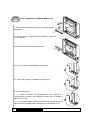
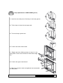
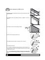
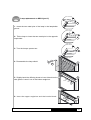
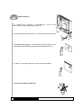
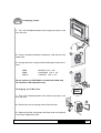
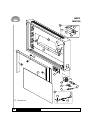
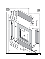
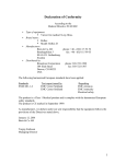
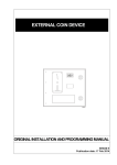
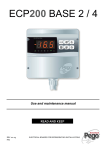
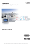
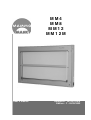
MM4
MM8
MM12
MM12M
User’s manual
Reference : 39786125818
Edition : C - 20/02/2003
Summary
Installation and maintenance should be performed by qualified service
personnel
Installation . . . . . . . . . . . . . . . . . . . . . . . . . . . . . . . . . . . . . . . . . . . . . . . . . . . . . . .p. 3
Shutter handling and brightness control . . . . . . . . . . . . . . . . . . . . . . . . . . . . . . .p. 4
Using the adjustable film grip option MM12 . . . . . . . . . . . . . . . . . . . . . . . . . . . . .p. 5
Front panel disassembly . . . . . . . . . . . . . . . . . . . . . . . . . . . . . . . . . . . . . . . . . .p. 6-7
Replacing tubes . . . . . . . . . . . . . . . . . . . . . . . . . . . . . . . . . . . . . . . . . . . . . . . .p. 8-11
Cleaning . . . . . . . . . . . . . . . . . . . . . . . . . . . . . . . . . . . . . . . . . . . . . . . . . . . . . . . .p. 12
Replacing fuses and filter . . . . . . . . . . . . . . . . . . . . . . . . . . . . . . . . . . . . . . . . . . .p.13
Replacing glass . . . . . . . . . . . . . . . . . . . . . . . . . . . . . . . . . . . . . . . . . . . . . . . . . .p. 14
Spare parts . . . . . . . . . . . . . . . . . . . . . . . . . . . . . . . . . . . . . . . . . . . . . . . . . . . .p.15-24
Technical and electrical characteristics . . . . . . . . . . . . . . . . . . . . . . . . . . . . . . . .p.25
Brightness control . . . . . . . . . . . . . . . . . . . . . . . . . . . . . . . . . . . . . . . . . . . . . . . .p. 26
General specifications . . . . . . . . . . . . . . . . . . . . . . . . . . . . . . . . . . . . . . . . . . . . .p. 27
2
Pièces détachées
Réf. : 39786125818 / Edition : C - 20/02/2003
Installation
MM
MM
MM
1 - Remove the red brackets
2 - Keyholes are on back of cabinet. Make
sure the sheetrock or masonry wall is solid.
3 - Mount the unit on the toggle bolts.
MM4 : 21Kg
MM8 : 37Kg
MM12 : 50Kg
MM12M : 54Kg
4 - Remove the protective Styrofoam slips
underneath glass.
5 - Use a 120V/60Hz - minimum 10 amp, grounded outlet.
6 - Leave minimum space for proper ventilation of device.
If the device is installed on a surface (table, desk...), use the feet
set option.
7 - Warning : do not cover vents, provide proper
support, do not enclose in cabinet, neither in a hot
environment.
Réf. : 39786125818 / Edition : C - 20/02/2003
Installation
3
Shutter movement and dimmer
1 - Vertical shutters : move the knobs from right to left to the
desired position.
2 - Horizontal sutters : move the knobs from top to bottom to the desired position.
3 - The knobs slide, do not twist knobs to move shutters
4 - Motorized shutters (MM12M)
5 - Dimmer control : turn clockwise to increase brightness.
Turn counterclockwise to reduce brightness.The normal
range is approximately a 50% luminance difference (not
turning radius). Please note that the lamps may flicker at
the low end of the rheostat range if the user continues turning the knob beyond its limit. Simply turn the system fully
on and slowly turn it down to determine the range.
4
PiècesUdétachées
se
Réf. : 39786125818 / Edition : C - 20/02/2003
Using the adjustable film grip MM12
1 - Loosen the two knobs of the film grip.
2 - Using the two knobs, place the film grip in the desired
position.
3 - Retighten the two knobs of the film grip.
4 - To insert film, slide it between the glass and the film grip.
The metal cylinders will support film.
5 - To remove film, simply pull it out.
Réf. : 39786125818 / Edition : C - 20/02/2003
PiècesUdétachées
se
5
Front panel disassembly
1 - Turn off the Mammomask, then unplug it.
2 - Remove the intensity control knob (2 recessed set screws
at 90°).
3 - Remove the two recessed screws at top, while keeping one
hand on the front panel to prevent it from falling forward.
4 - Gently tilt the front panel forward.
5 - Disconnect the ground wire.
6 - MM12M : Disconnect the terminal block
7 - Gently lift to remove the metal nibs protruding from bottom
edges of panel, tilt forward making sure the dimmer stem is not
damaged. Gently place the front panel on an appropriate
support, or against a wall. Do not turn upside down as the
glass can slide out.
6
M adétachées
intenance
Pièces
Réf. : 39786125818 / Edition : C - 20/02/2003
Front panel reassembly
1 - Tilt the front panel and place the two metal nibs in their
housing
2 - MM12M : Reconnect the terminal block
3 - Close the front panel, making sure the dimmer clears the
opening provided.
4 - Be sure the white beaded chain at bottom is not snagged on the interior light box.
5 - Reconnect the ground wire before closing front panel.
6 - Without letting go of the front panel, reinsert the screws
7 - Reinstall the dimmer knob.
8 - Reconnect the power cord.
Réf. : 39786125818 / Edition : C - 20/02/2003
M aPièces
i n t e n détachées
ance
7
Lamp replacement on MM4 & MM8 (part I)
1 - Remove the front panel and remove the upper metal
lamp shield.
2 - Gently bend the plastic diffusing sheet to remove it
from its guides.
3 - Remove the lower metal lamp shield.
4 - Turn the lamp to be changed a quarter turn.
5 - Tilt the lamp slightly to release its upper pins.
6 - Remove the lamp.
☞ - In order to maintain the performance of your product, it is
recommended to clean it and change the tubes every 6 months or
2000 hours of use.
☞ - It is recommended to change all lamps at the same time using
high luminance daylight lamps available from Broadwest Corp.
8
M adétachées
intenance
Pièces
Réf. : 39786125818 / Edition : C - 20/02/2003
Lamp replacement on MM4 & MM8 (part II)
1 - Insert the two metal pins of the lamp in the lower groove.
2 - Tilt the lamp to insert the two upper pins.
3 - Turn the lamp a quarter turn.
4 - Position the lower metal shield.
5 - Slightly bend the diffusing sheet to insert it in the
side guides. Lower into the channel of the bottom angle
bar.
6 - Position the upper metal shield.
7 - Make sure that the srews are tightened and reassemble
the front panel.
Réf. : 39786125818 / Edition : C - 20/02/2003
M Pièces
a i n t e ndétachées
ance
9
Lamp replacement on MM12 (part I)
1
1 - Remove the front panel and remove the knurled knob of the
upper bracket.
2 - Slightly bend the diffusing sheet to release it from its
guides.
2
3 - Remove one of the side lamp shields.
3
4
4 -Turn the old lamp a quarter turn.
5 - Slightly raise the lamp to release it from one end.
6 - Remove the lamp.
6
☞ - In order to maintain the performance of your product, it is
recommended to clean it and change the tubes every 6 months
or 2000 hours of use.
☞ - It recommended to change all lamps at the same time
using high luminance daylight lamps available from Broadwest
Corp.
10
M a détachées
intenance
Pièces
5
Réf. : 39786125818 / Edition : C - 20/02/2003
Lamp replacement on MM12 (part II)
1
1 - Insert the two metal pins of the lamp in the lampholder
groove.
2 - Tilt the lamp to insert the two metal pins in the opposite
lampholder.
2
3
3 - Turn the lamp a quarter turn.
4 - Reassemble the lamp shield.
3
4
5 - Slightly bend the diffusing sheet to insert it back into the
side guides. Lower it into in the bottom angle bar.
5
6 - Insert the upper angle bar and the knurled knob.
6
Réf. : 39786125818 / Edition : C - 20/02/2003
Maintenance
11
Maintenance
1 - Before any cleaning or maintenance, turn off the
Mammomask® and unplug the power cord.
2 - Housing of fluorescent lamps : use an alcohol-based cleaner.
3 - Altuglas diffusing panel: use a antistatic plastic cleaner, such
as Kleenmaster® Brillianize available from Broadwest Corp.
4 - Glass : use a glass cleaner or same product as above.
5 - Do not use water on the unit.
12
M adétachées
intenance
Pièces
Réf. : 39786125818 / Edition : C - 20/02/2003
Changing fuses
1 - Turn off the Mammomask® and unplug the power cord
from the filter.
2 - Using a miniature flathead screwdriver, slide out the fuse
holder tray.
3 - Change the fuses, using slow blow 3AG glass fuses as follows :
MM4 :
MM8 :
MM12 :
2A/250V 1.25’’ x 1/4’’
6.25A/250V 1.25’’ x 1/4’’
10A/250V 1.25’’ x 1/4’’
Do not connect to 220V/240V or invert fuse holder tray.
UL Listed for 120V operation only.
220-240V
Changing the EMI filter
110-120V
1 - Turn off the Mammomask® and remove the power cord
from the filter.
4 - Remove the two mounting screws from the filter.
5 - Remove the filter, disconnect the three wires on the back
of the filter. Replace the filter.
Réf. : 39786125818 / Edition : C - 20/02/2003
Maintenance
13
Changing the glass
1 - For MM12A or MM12MA with an adjustable center film
grip, remove the lower two screws of the rail as shown.
2 - Unfasten the two knobs of the film grip.
MM12
MM12 M
3 - Slide the film grip downwards, keeping it pressed against the
glass.
4 - Rotate the film grip, making sure the metal rollers do not
fall out.
MM12
5 - 6 - Lift straight up holding the top film grip to
MM12 M
remove the glass panel. For MM12 units where
the center film grip is permanently attached to the
glass, carefully lift straight up holding the top and center film grip.
MM4
MM8
MM12
MM12 M
MM12
MM12 M
7 - 8 - Follow the same steps in reverse order to reinstall.
14
Pièces
M a i n tdétachées
enance
Réf. : 39786125818 / Edition : C - 20/02/2003
MM4
MM8
9
2
1
4.1
4.4
4.2
4.3
6
10
5.2
5.1
8
7
✆:
Contact us
Réf. : 39786125818 / Edition : C - 20/02/2003
Spare parts
15
MM12
MM12M
4.3
4.4
4.1
(x8)
4.2 ( x 8 )
1
9
3
✆
6
10
8
7
5.2
✆ : Contact us
16
Spare parts
5.1
Réf. : 39786125818 / Edition : C - 20/02/2003
(x8)
MM4
MM8
MM12
11.1
✆ : Contact us
Réf. : 39786125818 / Edition : C - 20/02/2003
Spare parts
17
MM12 M
25
(x2)
11.1
26 ( x 2 )
5.1
5.2
28
29
26
(x2)
27
✆ : Contact us
18
Spare parts
(x2)
Réf. : 39786125818 / Edition : C - 20/02/2003
MM4
MM8
MM12
MM12 M
✆ : Contact us
Réf. : 39786125818 / Edition : C - 20/02/2003
Spare parts
19
MM4
MM8
MM12
MM12 M
20
Spare parts
Réf. : 39786125818 / Edition : C - 20/02/2003
MM4 : Spare parts list
Description
References
1
Lamp Holder set MM4 & MM8
2
High Luminance fluorescent tube 18W
3
Not applicable
4
Ballast - 40 Watt for two 18 Watt lamps
5
Potentiometer - dimmer stern
RHS
6
Rheostat circuit board
RH5
7
Powerd cord
PCMM
8
Fuse
4 amp
9
Starter 18W lamp
10
EMI filter
11
Front panel
12
White beaded chain
CH-4
13
Chain connecting spring
SA-2
14
Top shutter
MMS4-T
15
Left shutter
MMS4-L
16
Right shutter
MMS4-R
17
Shutter Knob
SK
18
Bottom shutter
19
not applicable (see local glass company)
20
Not applicable
21
Not applicable
22
Not applicable
23
Desktop mountig supports
24
Not applicable
Réf. : 39786125818 / Edition : C - 20/02/2003
LHS4/8
L18
SL40.314
FS-2
EMI 10 amp
MMS4-B
DMS
Spare parts
21
MM8 : Spare parts list
Desription
References
1
Lamp Holder set MM4 & MM8
2
High Luminance fluorescent tube 18W
3
Not applicable
4
Ballast - 40 Watt for two 18 Watt lamps
5
Potentiometer - dimmer stern
RHS
6
Rheostat circuit board
RH5
7
Powerd cord
8
Fuse
9
Starter 18W lamp
10
EMI filter
11
Front panel
12
White beaded chain
CH-4
13
Chain connecting spring
SA-2
14
Top shutter
MMS8-T
15
Left shutter
MMS8-L
16
Right shutter
MMS8-R
17
Shutter Knob
SK
18
Bottom shutter
19
not applicable (see local glass company)
20
Adjustable center film grip
21
Viewing canopy
22
Sliding adjustable magnifier
SM-8
23
Desktop mountig supports
DMS
24
Mobile stand
22
LHS4/8
L18
SL40.314
PCMM
6.25 amp
FS-2
EMI 10 amp
MMS8-B
Pièces détachées - Spare parts Réf. : 39786125818 / Edition : C - 20/02/2003
A
V-8
P-8
MM12 : Spare parts list
Description
References
1
Lamp Holder set MM12 & MM12M
2
High Luminance fluorescent tube 36W
L36
3
Knurled button
K12
4
Ballast - 40 Watt for one 36 Watt lamp
5
Potentiometer - dimmer stern
RHS
6
Rheostat circuit board
RH5
7
Powerd cord
8
Fuse
9
Starter 36W lamp
10
EMI filter
11
Front panel
12
White beaded chain
CH-4
13
Chain connecting spring
SA-2
14
Top shutter
MM12-T
15
Left shutter
MM12-L
16
Right shutter
MM12-R
17
Shutter Knob
SK
18
Bottom shutter
19
not applicable (see local glass company)
20
Adjustable center film grip
21
Viewing canopy
22
Sliding adjustable magnifier
23
Desktop mountig supports
24
Mobile stand
Réf. : 39786125818 / Edition : C - 20/02/2003
LHS12
SL40.314
PCMM
10 amp
FS-4
EMI 10 amp
MM12-B
A
V-12
SM-12
DMS
P
Spare parts
23
MM12M : Motorized MM12M : Spare parts list
Description
References
1
Lamp Holder set MM12 & MM12M
2
High Luminance fluorescent tube 36W
L36
3
Knurled button
K12
4
Ballast - 40 Watt for one 36 Watt lamp
5
Potentiometer - dimmer stern
RHS
6
Rheostat circuit board
RH5
7
Powerd cord
8
Fuse
9
Starter 36W lamp
10
EMI filter
11
Front panel
12
White beaded chain
CH-4
13
Chain connecting spring
SA-2
14
Top shutter
MM12-T
15
Left shutter
MM12-L
16
Right shutter
MM12-R
17
Shutter Knob
SK
18
Bottom shutter
19
not applicable (see local glass company)
20
Adjustable center film grip
21
Viewing canopy
22
Sliding adjustable magnifier
23
Desktop mountig supports
24
Mobile stand
25
Vertical shutters motor
MS-1
26
Stainless steel sprocket drive
SD-M
27
Directional shutter switch
SK-M
28
Horizontal shutter knob
MS-2
29
Power supply
24
Spare parts
LHS12
SL40.314
PCMM
10 amp
FS-4
EMI 10 amp
MM12-B
A
V-12
SM-12
DMS
P
HB24-1.2-A
Réf. : 39786125818 / Edition : C - 20/02/2003
Technical specifications
MM4
Weight : . . . . . . . . . . . . . .21 Kg / 46,3 lb
Dimensions :
Length. x height. x depth. :60 x 72 x 13 cm
. . . . . . . . . . . . . . . . .23,6 x 28,3 x 15,1 in
Illuminated area :
Length. x height. : . . . . . . . . . .38 x 45 cm
Electrical specifications
Rated voltage : . . . . . . . . . . .120V / 60Hz
Power consumption : . . . . . . . . . . . .90 W
Consumed current : . . . . . . . . . . . . .1,5 A
UL listed
Technical specifications
MM8
Weight : . . . . . . . . . . . . . . .37 Kg / 81,6 lb
Dimensions :
Length. x height. x depth. :103 x 72 x 13 cm
. . . . . . . . . . . . . . . . .40,6 x 28,3 x 15,1 in
Illuminated area :
Length. x height. : . . . . . . . . . .73 x 45 cm
Electrical specifications
Rated voltage : . . . . . . . . . . .120V / 60Hz
Power consumption : . . . . . . . . . . .300 W
Consumed current : . . . . . . . . . . . . . .5 A
UL listed
Technical specifications
MM12
Weight : . . . . . . . . . . . . . 50 Kg / 110,2 lb
Dimensions :
Length. x height. x depth. :131 x 87 x 13 cm
. . . . . . . . . . . . . . . . .51,6 x 34,3 x 15,1 in
Illuminated area :
Length. x height. : 108 x 27 + 108 x 27 cm
Electrical specifications
Rated voltage : . . . . . . . . . . .120V / 60Hz
Power consumption : . . . . . . . . . . .420 W
Consumed current : . . . . . . . . . . . . . .8 A
UL listed
Technical specifications
Motorized MM12
Weight : . . . . . . . . . . . . . . . 54 Kg / 119 lb
Dimensions :
Length. x height. x depth. :131 x 87 x 13 cm
. . . . . . . . . . . . . . . . .51,6 x 34,3 x 15,1 in
Illuminated area
Length. x height. : 108 x 27 + 108 x 28,5 cm
Electrical specifications
Rated voltage : . . . . . . . . . . .120V / 60Hz
Power consumption : . . . . . . . . . . .420 W
Consumed current : . . . . . . . . . . . . .8,1 A
Not UL listed
Réf. : 39786125818 / Edition : C - 20/02/2003
Technical characteristics
25
TP
Top panel
BP
Bottom panel
Brightness control
✓ Adjust the dimmer control to maximum, leaving the lights on at least 30 minutes before test is
performed.
✓ Measure brightness at the center point M.
✓ Measure the brightness at the four angles shown above.
✓ For MM12, perform the luminance test on each panel (TP and BP).
Criteria : ∆ = (Li -Lm) / Lm
Where : Li : luminance value at measured point (in Cd/m2)
Lm : luminance value at center point (in Cd/m2)
✘ Suggest testing in accordance with DIN 6856, European protocol as follows :
Lm > 2000 Cd/m2
26
Control
a = 8 cm
Points 1-2-3-4 : écart maximum/maximum deviation ∆ < 30%
Points 5-6-7-8 : écart maximum/maximum deviation ∆ <15%
Réf. : 39786125818 / Edition : C - 20/02/2003
General specifications
Class I medical product according to appendix IX of 93/42/EEC.
Meet the provisions of the 93/42/ECC Council Directive for Medical Devices and
comply with applicable part of the following standards :
EN 60-601-1 (1990)
EN 60-598 (1989)
DIN 6856
Meet the provisions of the 89/336/ECC Concil Directive for Electromagnetic
Compatibility and comply with the following standards :
EN 60-601-1-2 (1993)
CEI 60-601-1-2 (2001)
Electrical class : I type A.
Storage and use :
Storage
Use
Temperature °C -10°C à/to +40°C
+15°C à/to +30°C
Humidity %
20% à/to 90%
20% à/to 90%
Réf. : 39786125818 / Edition : C - 20/02/2003
Generals specifications
27