1
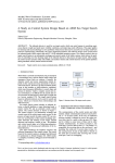
CP62101 6U Compact PCI 2 nd Generation Intel Core i7 Processor Board USER MANUAL REV1.2 Air Cooled version Conduction Cooled version LinkedHope Intelligent Technologies Co., Ltd CP62101 User Manual v1.2 File Status [ ] Draft [√] Officially released [ ] Being modified File Identifier Current Version 1.2 Authors T.Wang Completion Date G.Tian V.Zhao S.Hua st March 31 , 2014 Version History Version/Status Author 1.0 T.Wang 1.1 T.Wang Participants G.Tian V.Zhao G.Tian V.Zhao Start and end dates 10/1/2014 – 14/32014 15/3/2014 – 30/3/2014 G.Tian 1.2 T.Wang V.Zhao 31/3/2014 – S.Hua ~I~ Remark The first draft 1. Add Block Diagram 2. Add product assembly instructions 3. Modify BIOS option Remark 1. English version translated 2. Remove OS support to Windows2000 www.LinkHope.com CP62101 User Manual v1.2 CONTENT WARNING ................................................................................................................................................................................... 1 1. 2. I DESCRIPTION OF SAFETY SIGNS ..................................................................................................................................................... 1 II BASIC SAFETY PRECAUTIONS ......................................................................................................................................................... 2 III OTHER SAFETY PRECAUTIONS ....................................................................................................................................................... 2 IV THE OPERATION PROCEDURES....................................................................................................................................................... 2 INTRODUCTION ................................................................................................................................................................. 3 1.1 GENERAL ................................................................................................................................................................................. 3 1.2 BLOCK DIAGRAM ....................................................................................................................................................................... 4 HARDWARE INSTALLATION ................................................................................................................................................ 5 2.1 2.2.1 Installation of CPU Module ......................................................................................................................................... 5 2.2.2 Installation of PCBA ..................................................................................................................................................... 5 2.1 3. 4. CONDUCTION COOLED ................................................................................................................................................................ 5 AIR COOLED ............................................................................................................................................................................. 6 2.2.1 Installation of CPU Module ......................................................................................................................................... 6 2.2.2 Installation of PCBA ..................................................................................................................................................... 7 2.2.3 Installation of a XMC Module on CP62101 Boards...................................................................................................... 7 2.2.4 Installation of a front panel on CP62101 Boards......................................................................................................... 8 2.2.5 Installation of a XMC cover on CP62101 Boards ......................................................................................................... 9 SPECIFICATIONS ............................................................................................................................................................... 10 3.1 FUNCTIONAL SPECIFICATION ...................................................................................................................................................... 10 3.2 ENVIRONMENT SPECIFICATION ................................................................................................................................................... 10 3.2.1 Storage Temperature ................................................................................................................................................ 10 3.2.2 Working Temperature ............................................................................................................................................... 11 3.2.3 Power Requirement ................................................................................................................................................... 11 3.2.4 Board Size .................................................................................................................................................................. 11 3.2.5 Product Weight ......................................................................................................................................................... 11 PHYSICAL CHARACTERISTICS............................................................................................................................................ 12 4.1 MAIN COMPONENTS LOCATION .................................................................................................................................................. 12 4.2 JUMPER INTRODUCE................................................................................................................................................................. 13 4.3 FRONT PANEL CONNECTORS....................................................................................................................................................... 14 4.3.1 Front panel connectors drawings .............................................................................................................................. 14 4.3.2 Front panel RJ45 standard COM1 connector ............................................................................................................. 14 4.3.3 USB Connectors ......................................................................................................................................................... 15 4.3.4 VGA Connector on Front Panel .................................................................................................................................. 15 4.3.5 CPCI Connectors ........................................................................................................................................................ 16 4.4 CP62101 RESOURCES ASSIGNMENT ........................................................................................................................................... 20 4.4.1 I/O Resource .............................................................................................................................................................. 20 4.4.2 Interrupt Request (IRQ) Lines .................................................................................................................................... 20 ~ II ~ www.LinkHope.com CP62101 User Manual v1.2 5. 4.4.3 PCI Devices ................................................................................................................................................................ 21 4.4.4 Memory Resource ..................................................................................................................................................... 22 4.4.5 SMBUS ....................................................................................................................................................................... 23 BIOS SETTING .................................................................................................................................................................. 24 5.1 ENTERING THE BIOS ................................................................................................................................................................ 24 5.2 MAIN .................................................................................................................................................................................... 25 5.3 ADVANCED ............................................................................................................................................................................. 26 5.4 CHIPSET ................................................................................................................................................................................. 36 5.5 BOOT .................................................................................................................................................................................... 49 5.6 SECURITY ............................................................................................................................................................................... 51 5.7 SAVE & EXIT ........................................................................................................................................................................... 52 ~ III ~ www.LinkHope.com CP62101 User Manual v1.2 0 CHAPTER WARNING Thank you for choosing LinkedHope’s CP62101 processor board, the relevant safety precautions for this product are described as below. The operator and all staff who may be involved in the operation must be fully aware of the contents of this manual to ensure the safety of persons and device. I Description of safety signs Safety signs involved in the device means as following: Prohibitions: No smoking Smoking is prohibited while the device is working No burning Burning is prohibited while the device is working Ensure fire safety facilities / equipment in good condition No demolition Warnings Warning danger Warning electric shock -1- www.LinkedHope.com CP62101 User Manual v1.2 II Basic safety precautions 1) The operator should go through the system operation training, and Maintenance personnel should go through the system maintenance training 2) The device must be powered on and powered off according to the procedure set forth herein III Other safety precautions It is recommended to use anti-static gloves to prevent electrostatic damage, when plug and unplug the device. The device needs to be put into static bag when it was transported in single board or was stored When transporting the device, the package should be fitted with shock-absorbing protective measures to prevent extrusion, collision or damage during the transport process. When the device needs to be stored , you should pay attention to ventilation, damp proof, dust proof, not stored together with corrosive substances IV The operation procedures The hardware configuration should be in accordance with the instructions jumper 3.2 and the user’s needs; check the device connected to the board to make sure the connection is correct, particularly check if the output voltage(+12V, +5V,+3.3V) of power supply equipment meets the requirements or not. -2- www.LinkedHope.com CP62101 User Manual v1.2 1 CHAPTER 1. INTRODUCTION 1.1 General CP62101 is a 6U CPCI processor board base on Intel QM67/HM65 chipset and Intel® Core™ 2nd generation i3/i5/i7 processors. Frequency up to 2.5 GHz, integrated core graphics HD3000, the double channel SO DIMM memory, maximum support with ECC (optional) 16 GB DDR3 memory, (1333/1066/800).16GB on board SSD is designed with SATA 3.0 interface for data safety and quick storage. PCI bus bit type and bandwidth are all optional from 32bit/64bit and 33MHz/66MHz. CP62101 reserved all kinds of interfaces, such as SATAII, SATAIII, USB2.0, USB3.0, Ethernet. CP62101 supports Dual-head, Multi-head display output, including VGA, DVI and HDMI. Maximum CRT output resolution is designed as 2048x1536. This processor board is powerful steady and especially suitable for the calculation of all kinds of compatible IPC and computer processing center for hush environment. -3- www.LinkedHope.com CP62101 User Manual v1.2 1.2 Block Diagram FrontPanel GBE3 GBE4 Mag. Mag. 1x COM RJ45 2xUSB VGA Uart to RS232 HIN213EIAZ-T DP PMC 82574IT 1xUART SCH3114 SuperIO SIO LPC PCIe x1 VGA Switch 2xUART MAX488 5ETJ+ CRT GBE4 VGA XMC PCIe x16 2xUSB COMexpress Type 6 1xSATA PCIe x1 2x DP 4xUSB HDA GBE SW PI3L500A/? Uart to RS232 HIN213EIAZ-T X2/Uart direct SATA SSD 16G PCIe to PCI PI7C9X130 Mag. 64Bit/66MHz Mag. GPIO 3xSATA PCIe x4 82574IT LED/RST GBE1 J3 GBE2 J3 PCI J1 PCI J2 2xDP J5 4xUSB J3 3xSATA J5 VGA J3 3xRS232/ Uart J3 GPIO J5 Rear IO -4- www.LinkedHope.com CP62101 User Manual v1.2 2 CHAPTER 2. HARDWARE INSTALLATION 2.1 Conduction Cooled 2.2.1 Installation of CPU Module 1) Place the module back upward 2) Align the screw holes and the radiator module placement 3) Install the 5 pan head screws 2.2.2 Installation of PCBA The radiator is mounted on the PCBA use screws -5- www.LinkedHope.com CP62101 User Manual v1.2 2.1 Air Cooled 2.2.1 Installation of CPU Module 1) Place the module back upward 2) Align the screw holes and the radiator module placement 3) Install the 5 pan head screws -6- www.LinkedHope.com CP62101 User Manual v1.2 2.2.2 Installation of PCBA The radiator is mounted on the PCBA use screws 2.2.3 Installation of a XMC Module on CP62101 Boards 1) Remove the top side cover. 2) Align the holes at the front and middle of the XMC module with the matching holes on the CP62101. 3) Lower the XMC module, component side down, fitting the XMC connectors into their mating connectors on the CP62101. Press them together so that the friction from the pins holds the XMC module in place. 4) Install the 8 pan head screws. -7- www.LinkedHope.com CP62101 User Manual v1.2 2.2.4 Installation of a front panel on CP62101 Boards -8- www.LinkedHope.com CP62101 User Manual v1.2 2.2.5 Installation of a XMC cover on CP62101 Boards -9- www.LinkedHope.com CP62101 User Manual v1.2 3 CHAPTER 3. SPECIFICATIONS 3.1 Functional Specification Support Intel® Core™2 i3/i5/i7 processors and Intel® Celeron processor Intel QM67 chipset (i3, i5, i7 series CPU); Intel HM65 chipset (Celeron series CPU) Compatible different PCI bus, 64-bit/66(133) MHz and 32-bit/33 MHz, Up to support 7 peripheral PCI slots On board dual channel DDR3 1333MHz SO-DIMM, up to 16GB memory module supported On board SSD SLC up to 64GB Three SATA interfaces via rear CPCI connector One VGA display interface switchable between front and rear panel, maximum CRT output resolution is 2048 x 1536 Two DP interfaces via rear CPCI connector Three Gigabit Ethernet interfaces , via rear CPCI connector One Gigabit Ethernet switchable between front and rear panel Three serial communication interfaces RS-232/TTL optional and the forth one is RS-422/RS-232/TTL optional Two USB2.0 interfaces in front panel and 4 USB3.0 through rear panel On board one XMC interface On board one PMC interface 5V, 3.3V CompactPCI VIO configurable One I2C interface via rear CPCI connector 1-255 grade watch dog EEPROM BIOS, data backup without battery except RTC clock The same PCB for Air Cooling version and conduction cooling version Operating system support includes MS-DOS/Windows7/XP/VxWorks /Linux 3.2 Environment Specification 3.2.1 Storage Temperature The CP62101 might be malfunction and be mechanically damaged if stored out of the temperature - 10 - www.LinkedHope.com CP62101 User Manual v1.2 range from -55℃ to +85℃. 3.2.2 Working Temperature The working temperature of CP62101 can be extended to -40~+70℃ as industrial grade, and CP62101 is fully tested in such condition and is able to work normally within the scope of PICMG 2.1 specification. 3.2.3 Power Requirement The power consumption CP62101 is about 45 Watt with Intel® i7 2655LE processor running at full speed (exact power consumption will be difference for difference on board CPU). The primary power inputs of CP62101 is +5V, +3.3V and +12V. however, The CP62101 processor board can only endure less than ±5%noise on the power rail. 3.2.4 Board Size Length x Width: 233×160 (mm) Height: 4HP 3.2.5 Product Weight Conduction cooled:Less than 1200g including head sink Air Cooled:Less than 1100g including head sink - 11 - www.LinkedHope.com CP62101 User Manual v1.2 4 CHAPTER 4. PHYSICAL CHARACTERISTICS 4.1 Main Components Location Main components location as below: 3-1 - 12 - www.LinkedHope.com CP62101 User Manual v1.2 The jumper and connector functional definition are shown as below: CN1 system reset button (RST) CN2 RJ45 serial port connector CN3 VGA connector CN4 Front USB connector CN5,CN6 Ethernet connectors CN7 Front panel status light CN8 XMC connector CN9 PMC connector CN10 VGA front-rear switch CN11 Ethernet front-rear switch J1/J2/J3/J4/J5 CPCI connector table 3-1 Jump and connector 4.2 Jumper Introduce Because all jumpers and front I/Os are covered by heat sink on conduction cooling version, LinkedHope has to fix all jumper configurations during the CP62101 board assembly process. Users could set Ethernet and VGA output from front or rear via connector CN11 and CN10. The relationship between switch and function has shown below: CONN Status Function CN10 Close VGA output from rear Open VGA output from front CN11 Close GbE output from front Open GbE output from rear Table 3-2 Status Function front-rear switch setting all factory default configuration of CP62101 will be from front panel if no statement. - 13 - www.LinkedHope.com CP62101 User Manual v1.2 4.3 Front Panel Connectors 4.3.1 Front panel connectors drawings Figure 3-2 The left drawing is no XMC board installed,the right drawing is XMC board installed 4.3.2 Front panel RJ45 standard COM1 connector CN2 in front panel is standard RJ45 connector serial communication port COM1. It can be connected to standard UART device. Figure 3-3 and table 3-3 is pin out description. Figure 3-3 PIN 1 2 3 4 5 6 7 8 Signal RTS# DTR# TXD GND GND RXD DSR# CTS# Table 3-3 - 14 - www.LinkedHope.com CP62101 User Manual v1.2 4.3.3 USB Connectors Six USB ports are supported on this board. Two ports are on board USB2.0, the other four are USB3.0 connected to rear I/O. User Instructions 1) Must use qualified USB device and make sure ground connection well done. The board might be damaged in case the USB ground connection is not performed. 2) Please touch chassis to discharge before using USB device. 3) Please make sure Operating System is in “Ready” status when you remove USB device. Figure 3-4 CN4 pin out definition Pin 1 2 3 4 Signal +5V -Data +Data GND Table 3-4 On board USB definition 4.3.4 VGA Connector on Front Panel CN3 is a standard VGA connector (DB15). Figure 3-5 and table 3-5 are CN3 pin out description. Figure 3-5 PIN SIGNAL PIN SIGNAL 1 VGA_R_R 2 VGA_G_R 3 VGA_B_R 4 NC 5 GND 6 GND 7 GND 8 GND 9 VCC_VGA 10 GND 11 NC 12 VGA_DDAT_S 13 VGA_HSY_S 14 VGA_VSY_S 15 VGA_DCLK_S 16 GND Table 3-5 On board VGA CN3 definition - 15 - www.LinkedHope.com CP62101 User Manual v1.2 4.3.5 CPCI Connectors J1 connector pin out definition (PCI bus) PIN Z A B C D E F 1 GND +5V -12V TRST_L +12V +5V GND 2 GND TCK +5V TMS NC TDI GND 3 GND S_INTA_L S_INTB_L S_INTC_L +5V S_INTD_L GND 4 GND IPMB PWR GND V(I/O) INTP INTS GND 5 GND RSV RSV PCI_RST_D GND S_GNT0 GND 6 GND S_REQ0 GND +3.3V S_CLKOUT0 S_AD31 GND 7 GND S_AD30 S_AD29 S_AD28 GND S_AD27 GND 8 GND S_AD26 GND V(I/O) S_AD25 S_AD24 GND 9 GND S_C/BE3 NC S_AD23 GND S_AD22 GND 10 GND S_AD21 GND +3.3V S_AD20 S_AD19 GND 11 GND S_AD18 S_AD17 S_AD16 GND S_C/BE2 GND 15 GND +3.3V S_FRAME_L S_IRDY_L GND S_TRDY_L GND 16 GND S_DEVSEL_L PCIXCAP V(I/O) S_STOP_L S_LOCK_L GND 17 GND +3.3V IPMB SCL IPMB SDA GND S_PEER_L GND 18 GND S_SEER_L GND +3.3V S_PAR S_C/BE1 GND 19 GND +3.3V S_AD15 S_AD14 GND S_AD13 GND 20 GND S_AD12 GND V(I/O) S_AD11 S_AD10 GND 21 GND +3.3V S_AD9 S_AD8 S_M66EN S_C/BE0 GND 22 GND S_AD7 GND +3.3V S_AD6 S_AD5 GND 23 GND +3.3V S_AD4 S_AD3 +5V S_AD2 GND 24 GND S_AD1 +5V V(I/O) S_AD0 S_ACK64_L GND 25 GND +5V S_REQ64_L ENMU_R# +3.3V +5V GND 12 13 14 Table 3-8 J2 connector signal pin out definition (PCI bus) - 16 - PIN Z A B C D E F 1 GND S_CLKOUT1 GND S_REQ1 S_GNT1 S_REQ2 GND 2 GND S_CLKOUT2 S_CLKOUT3 GND S_GNT2 S_REQ3 GND 3 GND S_CLKOUT4 GND S_GNT3 S_REQ4 S_GNT4 GND 4 GND V(I/O) RSV S_C/BE7 GND S_C/BE6 GND 5 GND S_C/BE5 dev64 V(I/O) S_C/BE4 S_PAR64 GND 6 GND S_AD63 S_AD62 S_AD61 GND S_AD60 GND 7 GND S_AD59 GND V(I/O) S_AD58 S_AD57 GND www.LinkedHope.com CP62101 User Manual v1.2 8 GND S_AD56 S_AD55 S_AD54 GND S_AD53 GND 9 GND S_AD52 GND V(I/O) S_AD51 S_AD50 GND 10 GND S_AD49 S_AD48 S_AD47 GND S_AD46 GND 11 GND S_AD45 GND V(I/O) S_AD44 S_AD43 GND 12 GND S_AD42 S_AD41 S_AD40 GND S_AD39 GND 13 GND S_AD38 GND V(I/O) S_AD37 S_AD36 GND 14 GND S_AD35 S_AD34 S_AD33 GND S_AD32 GND 15 GND RSV GND FAL# SW_REQ1# SW_GNT1# GND 16 GND RSV RSV DEG# GND RSV GND 17 GND RSV GND SYS_RESET1# SW_REQ2# SW_GNT2# GND 18 GND RSV RSV RSV GND RSV GND 19 GND GND GND IPMB2 SDA IPMB2_SCL IPMB2_Alert GND 20 GND PCICLK1 GND RSV GND RSV GND 21 GND PCICLK2 GND RSV RSV RSV GND 22 GND GA4 GA3 GA2 GA1 GA0 GND Table 3-9 J3 connector signal pin out definition PIN Z A B C D E F 1 GND COM2_RTS# COM2_RX COM2_DSR# COM2_DCD# RIO_ID1 GND 2 GND COM2_RI# COM2_DTR# COM2_CTS# COM2_TX COM4_TX GND 3 GND COM4_DTR# COM4_RTS# COM3_RX_N COM3_RX_P COM4_RX GND 4 GND COM4_CTS# COM4_DSR# COM3_TX_N COM3_TX_P COM4_DCD# GND 5 GND VGA_BLUE VGA_HSYNC VGA_VSYNC VGADDC_CLK COM4_RI# GND 6 GND VGA_RED VGA_GREEN VGADDC_DATA DEBUG_CLK DEBUG_DATA GND 7 GND VCC_RIO_3.3V COM3_RTS# GPIO1 GPIO2 SPEAKER GND 8 GND R_USB_1_N R_USB_1_P GND R_USB_3_N R_USB_3_P GND 9 GND R_USB_2_N R_USB_2_P GND R_USB_4_N R_USB_4_P GND 10 GND R_USB2_VCC R_USB1_VCC GND R_USB4_VCC R_USB3_VCC GND 11 GND COM3_RI# +12V_add GND +12V_add +12V_add GND 12 GND COM3_DCD# +12V_add GND +12V_add +12V_add GND 13 GND GBE1_ACT GBE2_ACT COM3_CTS# +12V_add FAN_SENSE1 GND 14 GND GBE1_LNK GBE2_LNK Lpab_CT1 +12V_add FAN_SENSE2 GND 15 GND GBE2_MDI1_P GBE2_MDI1_N GND GBE2_MDI3_P GBE2_MDI3_N GND 16 GND GBE2_MDI0_P GBE2_MDIO_N GND GBE2_MDI2_P GBE2_MDI2_N GND 17 GND GBE1_MDI1_P GBE1_MDI1_N GND GBE1_MDI3_P GBE1_MDI3_N GND 18 GND GBE1_MDI0_P GBE1_MDI0_N GND GBE1_MDI2_P GBE1_MDI2_N GND 19 GND VCC_RIO VCC_RIO VCC_RIO_3.3V +12V -12V GND Table 3-10 J3 connector signal definition Signal - 17 - Definition www.LinkedHope.com CP62101 User Manual v1.2 COM2,COM4 COM2,COM4 Signaling (RS-232/TTL) COM3 COM3Signaling (RS-422/RS-232/TTL) VGA VGA Signal USB1 _P to USB4_P USB Port Signaling FAN 1,2 Fan Sensoring SPEAKER Standard PC Speaker GBE1,2,3 Rear I/O LAN 1,LAN2,LAN3 +12V_add +12V power R_USB_VCC USB power J4 connector signal pin out definition PIN Z A B C D E F 1 GND PIM_61 PIM_63 GND PIM_62 PIM_64 GND 2 GND PIM_57 PIM_59 GND PIM_58 PIM_60 GND 3 GND GND GND GND GND GND GND 4 GND PIM_53 PIM_55 GND PIM_54 PIM_56 GND 5 GND PIM_49 PIM_51 GND PIM_50 PIM_52 GND 6 GND GND GND GND GND GND GND 7 GND PIM_45 PIM_47 GND PIM_46 PIM_48 GND 8 GND PIM_41 PIM_43 GND PIM_42 PIM_44 GND 9 GND GND GND GND GND GND GND 10 GND PIM_37 PIM_39 GND PIM_38 PIM_40 GND 11 GND PIM_33 PIM_35 GND PIM_34 PIM_36 GND 15 GND PIM_29 PIM_31 GND PIM_30 PIM_32 GND 16 GND PIM_25 PIM_27 GND PIM_26 PIM_28 GND 17 GND GND GND GND GND GND GND 18 GND PIM_21 PIM_23 GND PIM_22 PIM_24 GND 19 GND PIM_17 PIM_19 GND PIM_18 PIM_20 GND 20 GND GND GND GND GND GND GND 21 GND PIM_13 PIM_15 GND PIM_14 PIM_16 GND 22 GND PIM_9 PIM_11 GND PIM_10 PIM_12 GND 23 GND NC VCC_RIO GND NC VCC_RIO_3.3V GND 24 GND PIM_5 PIM_7 GND PIM_6 PIM_8 GND 25 GND PIM_1 PIM_3 GND PIM_2 PIM_4 GND 12 13 14 Table 3-12 J5 connector signal pin out definition - 18 - www.LinkedHope.com CP62101 User Manual v1.2 PIN Z A B C D E F 1 GND GND GND GND GND GND GND 2 GND SATA1_RX_P SATA1_RX_N GND SATA1_TX_P SATA1_TX_N GND 3 GND GND GND GND GND GND GND 4 GND SATA2_RX_P SATA2_RX_N GND SATA2_TX_P SATA2_TX_N GND 5 GND GND GND GND GND GND GND 6 GND SATA3_RX_P SATA3_RX_N GND SATA3_TX_P SATA3_TX_N GND 7 GND GND GND GND GND GND GND 8 GND HT3_TX+ HT3_TX- GND HT3_RX+ HT3_RX- GND 9 GND GND GND GND GND GND GND 10 GND HDMI1_CLK_P HDMI1_CLK_N GND SMB_DAT SMB_CK GND 11 GND COM1_RTS# HDMI1_HPD GND HDMI1_CRTLCLK_N HDMI1_CTRLCLK_P GND 12 GND HDMI1_DATA2_P HDMI1_DATA2_N GND COM1_RI# COM1_RX GND 13 GND HDMI1_DATA0_P HDMI1_DATA0_N GND HDMI1_DATA1_P HDMI1_DATA1_N GND 14 GND GND GND GND GND GND GND 15 GND HDMI2_CLK_P HDMI2_CLK_N GND HDMI2_CTRLCLK_N HDMI2_CTRLCLK_P GND 16 GND COM1_DTR# HDMI2_HPD GND COM1_CTS# COM1_DCD# GND 17 GND HDMI2_DATA2_P HDMI2_DATA2_N GND HDMI2_DATA1_P HDMI2_DATA1_N GND 18 GND HDMI2_DATA0_P HDMI2_DATA0_N GND GND GND GND 19 GND GND GND GND AC_SDIN0 AC_BITCLK GND 20 GND COM1_TX AC_SDIN1 GND COM1_DSR# AC_SDIN2 GND 21 GND AC_SYNC AC_RST# GND AC_SDOUT SYS_WP# GND 22 GND ACA_ACT# PWM1_OUT GND PWM2_OUT V_BAT GND Table 3-13 J5 connector signal definition Signal Definition SATA1,2,3 SATA Port 1.2.3 Signaling SMB System Management Bus Signaling HDMI1 HDMI1 /DP1 signaling HDMI2 HDMI2/DP2 AC_.. High-definition audio signaling PWM Pulse width modulation output for fan COM1 COM1 Signaling (RS-232/TTL) HT0..3 NOT connected (no signal signaling definition) Table 3-14 - 19 - www.LinkedHope.com CP62101 User Manual v1.2 4.4 CP62101 Resources Assignment 4.4.1 I/O Resource The I/O-port addresses of the board are functionally identical to a standard PC/AT. All addresses not mentioned in this table should be available. We recommend that you do not use I/O addresses below 0100h with additional hardware for compatibility reasons, even if available. I/O Address Used for Available Comment 0000-001F System Resources No fixed 0020-003F Interrupt Controller No fixed 003E-002F Ext. SIO No fixed 0040-005F Timer, Counter No fixed 004E-004F TPM No fixed 0060-006F Keyboard controller No fixed 0070-007F RTC and CMOS Registers No fixed 0080 BIOS Postcode No fixed 0081-009F DMA Controller No fixed 00A0-00BF Interrupt Controller No fixed 00C0-00DF DMA Controller No fixed 00F0-00FF Math Coprocessor No fixed 0290-029F Ext. SIO No fixed 03B0 -03DF VGA No fixed 0040-047F Chipset No fixed 04D0-04D1 Chipset No fixed 0500-057F Chipset No fixed 0680-069F Chipset No fixed 0B78-0B7F Chipset No fixed 0CF8-0CFF Chipset No fixed Table 3-16 CP62101 I/O Resource 4.4.2 Interrupt Request (IRQ) Lines IRQ# 0 - 20 - Used for Available Timer0 No Comment - www.LinkedHope.com CP62101 User Manual v1.2 1 Keyboard No - 2 Cascade No 3 External SIO-COM2 Ext. SIO Dynamic(BIOS default) 4 External SIO-COM1 Ext. SIO Dynamic(BIOS default) 5 External SIO-LPT1 Ext. SIO Dynamic(BIOS default) 6 - Ext. SIO 7 - Ext. SIO 8 RTC No - 9 ACPI No - 10 - Ext. SIO 11 SMBus No - 12 PS/2 Mouse No - 13 FPU No 14 - No - 15 - No - 16 LNKA No PCIe RP0+PCIe RP4+USB EHCI+ Intel ME+I.G.D 17 LNKB No PCIe RP1+PCIe RP5+PCIe2Pata 18 LNKC No PCIe RP2+PCIe RP6+PCIe2PCI 19 LNKD No PCIe RP3+SATA AHCI 20 LNKE No (b) 21 LNKF No (b) 22 LNKG No (b) 23 LNKH No (b) - - - - Table 3-17 IRQ Note: a) If the “Used For” device is disabled in setup, the corresponding interrupt is available for other device. b) ACPI OS decides on particular IRQ usage 4.4.3 PCI Devices All devices follow the Peripheral Component Interconnect 2.3 (PCI 2.3) respectively the PCI Express Base 1.0a specification. The BIOS and OS control memory and I/O resources. Please see the PCI 2.3 specification for details. - 21 - PCI Device B:D:F Host Bridge 0:0:0 PCI IRQ None Interface Comment internal Chipset www.LinkedHope.com CP62101 User Manual v1.2 P.E.G. Root Port 0:1:0 LNKA internal Chipset Video Controller 0:2:0 LNKA internal Chipset ME 0:22:0 LNKA internal Chipset GbE 0:25:0 LNKE PCIe Chipset HDA 0:27:0 LNKG PCIe Chipset PCIe Port0 0:28:0 LNKA internal Chipset A/B/C/D PCIe Port0 LNKA internal Chipset B/C/D/A PCIe Port1 LNKA internal Chipset C/D/A/B PCIe Port2 LNKA internal Chipset D/A/B/C PCIe Port3 LNKA internal Chipset A/B/C/D PCIe Port4 LNKA internal Chipset B/C/D/A PCIe Port5 LNKA internal Chipset C/D/A/B PCIe Port6 0:28:7 LNKA internal Chipset EHCI 0:29:0 LNKH internal Chipset LPC Bridge 0:31:0 - internal Chipset SATA 0:31:2 LNKD internal Chipset SMBus 0:31:3 LNKC internal Chipset PCIe2PATA X:00:0 LNKA PCIe Slot5 PCIe2PCI Y:00:0 LNKA PCIe Slot6 PCIe Port0 Slot - PCIe Port1 0:28:1 PCIe Port1 Slot PCIe Port2 0:28:2 PCIe Port2 Slot PCIe Port3 0:28:3 PCIe Port3 Slot PCIe Port4 0:28:4 PCIe Port4 Slot PCIe Port5 0:28:5 PCIe Port5 Slot PCIe Port6 0:28:6 PCIe Port6 Slot PCIe Port7 Table 3-19 PCI Devices 4.4.4 Memory Resource The first 640 KB of DRAM are used as main memory. Using DOS, you can address 1 MB of memory directly. Memory area above 1 MB (high memory, extended memory) is accessed under DOS via special drivers such as HIMEM.SYS and EMM386.EXE, which are part of the operating system. Please refer to the operating system documentation or special textbooks for information about HIMEM.SYS and EMM386.EXE. Other operating systems (Linux or Windows versions) allow you to address the full memory area directly. - 22 - www.LinkedHope.com CP62101 User Manual v1.2 Upper Memory Used for Available A0000h-BFFFFh VGA Memory No Mainly used by graphic controller C0000h-CFFFFh VGA BIOS No Used by onboard VGA ROM Yes Free for shadow RAM in standard config D0000h-DFFFFh Comment E0000h-FFFFFh System BIOS No Fixed 20000000h-201FFFFFh IGFX No Fixed 40000000h-401FFFFFh IGFX No Fixed E0000000h-FEAFFFFh PCIe Config Space No Fixed FED00000h-FED00EFFh HPET No Fixed FED10000h-FED17FFFh MCH No Fixed FED18000h-FED18FFFh DMI No Fixed FED19000h-FED19FFFh EPBA No Fixed FED1C000h-FED1FFFh RCBA No Fixed FED20000h-FED3FFFFh TXT No Fixed FED40000h-FED44FFFh TPM No Fixed FED45000h-FED8FFFFh TPM No Fixed FED90000h-FED93FFFh VT-d No Fixed FEE00000h-FEEFFFFFh IOxAPIC No Fixed FF000000h-FFFFFFFFh BIOS Flash No Fixed Table 3-20 Memory Resource 4.4.5 SMBUS - 23 - Address Device Comment 12h SMART_CHARGER Not to be used with any SM bus device except a charger 14h SMART_SELECTOR Not to be used with any SM bus device except a Selector manager 16h SMART_BATTERY Not to be used with any SM bus device except a battery 5Ch HW Monitor Do not use under any circumstances A0h DDR3 Chanel A Do not use under any circumstances 30h DDR3 Thermal Chan. A Do not use under any circumstances A4h DDR3 Chanel A Do not use under any circumstances 34h DDR3 Thermal Chan. A Do not use under any circumstances www.LinkedHope.com CP62101 User Manual v1.2 5 CHAPTER 5. BIOS Setting 5.1 Entering the BIOS The AMI® BIOS Setup Utility, also named AMI® Aptio Setup Utility, changes system behavior by modifying firmware configuration. The setup program use a number of menus to turn feature on or off, the sequence of bootable device can be also modified by this setup program. User can press <F2> or <Del> key during BIOS POST to enter BIOS setup utility. The Setup menu is quite extensive, and is provided with context-sensitive help information, which is displayed in the right-hand panel on screen. Functional keystrokes in POST: Key Function DEL Enter BIOS Setup F2 Enter BIOS Setup F7 Boot Menu Ctrl + I Raid Config Setup Key used in BIOS setup utility: Key Function ← or → Arrow key Select a menu. ↑ or ↓ Arrow key Select fields in current menu. <Home> or <End> Move cursor to top or bottom of current window. <PgUp> or <PgDn> Move cursor to next or previous page. +/- Change Option <Enter> Execute command or select submenu. <F1> General Help window. <F2> Previous Values <F3> Load the optimized default configuration. <F4> Save and exit. <Esc> Exit menu. - 24 - www.LinkedHope.com CP62101 User Manual v1.2 5.2 Main Feature Option Description System Language English Use this function to select the system language. Currently, only English is supported. System Date <WD MM/DD/YYYY> Use this function to change the system date. Select System Date using the Up and Down <Arrow> keys. Enter the new values through the keyboard or press +/- to increment/decrement values. Use “Tab” to switch between date elements. System Time <HH:MM:SS> Use this function to change the system time. Select System Time using the Up and Down <Arrow> keys. Enter the new values through the keyboard or press +/- to increment/decrement values. Use “Tab” to switch between time elements. - 25 - www.LinkedHope.com CP62101 User Manual v1.2 5.3 Advanced PCI Subsystem Settings - 26 - www.LinkedHope.com CP62101 User Manual v1.2 Feature Option Description PCI ROM Priority EFI Compatible ROM In case of multiple Option ROMs (Legacy and EFI Compatible), Legacy OPROM specifies what PCI Option ROM to launch 32 PCI Bus Clocks Value to be programmed into PCI Latency Timer Register CI Latency Timer 64 PCI Bus Clocks 128 PCI Bus Clocks 256 PCI Bus Clocks VGA Palette Snoop Enabled Enables or Disables VGA Palette Registers Snooping Disabled PERR# Generation Enabled Enables or Disables PCI Device to Generate PERR# Disabled SERR# Generation Enabled Enables or Disables PCI Device to Generate SERR# Disabled 63 ACPI Settings Feature Option Description Enable ACPI Auto configuration Enabled Enables or Disables BIOS ACPI Auto Configuration Disabled Enable Hibernation - 27 - Enabled Enables or Disables System ability to Hibernate (OS/S4 Sleep Disabled State) www.LinkedHope.com CP62101 User Manual v1.2 ACPI Sleep State Lock Legacy Resources S3(Suspend to RAM) Select the highest ACPI sleep state the system will enter when S4(Suspend to Disk) the SUSPEND button is pressed Enabled Lock the legacy resources Disabled CPU Configuration Feature Option Description Hyper-threading Enabled Enables/Disables the IntelR Hyper Threading Technology HTT Disabled supported by Core i7/i5/i3 All Number of cores to enable in each processors package Active Proc Cores 1 2 3 Execute Disable Bit Hardware Prefetcher Enabled XD can prevent certain classes of malicious buffer overflow Disabled attacks when combined with a supporting OS Enabled Turn on/off the MLC streamer prefetcher Disabled Adj.Cache Line Pref Enabled Turn on/off prefetching of adjacent cache lines Disabled Intel Virtualizition Technology Enabled Enable Intel VT funciton Disabled - 28 - www.LinkedHope.com CP62101 User Manual v1.2 CPU PPM Configuration Feature Option Description CPU DTS Enabled Enables/Disables CPU digital thermal sensors Disabled EIST Enabled Enables/Disables the Intel Speedstep Technology (E)IST Disabled Turbo Mode Enabled Enables/Disables the Intel Processor Turbo Mode 2.0 Disabled CPU C3 Report Enabled Enable/Disable C3 State Disabled CPU C6 report Enabled Enable/Disable C6 State Disabled CPU C7 report Enabled Enable/Disable C7 State Disabled Long duration pwr lim 0 Turbo options Long duration time 28 Turbo options Short duration power limit 0 Turbo options TCC active offset 0 Offset from factory set TCC activation temperature at which the Thermal Control Circuit must be activated. Tcc will be activated at: TCC Activation Temp - TCC Activation Offset - 29 - www.LinkedHope.com CP62101 User Manual v1.2 Miscellaneous Thermal Configuration - 30 - www.LinkedHope.com CP62101 User Manual v1.2 Feature Option Description Critical Trip Point POR This value controls the temperature of the ACPI Critical Trip Point - the 15°C point in which the OS will shut the system off. Note: 100°C is the Plan … Of Record (POR) for all Intel mobile processors 127°C ActTPnt Low Temp Disabled This value controls the temperature of the ACPI Active Low Trip Point - 15°C the point in which the OS will turn the processor fan on Active Trip .. Point Low Fan Speed. 55°C … 95°C ActTPnt Low Fan Speed 70 Active Trip Point Low Fan Speed in percentage. Value must be between 33% - 100%. This is the speed at which fan will run when Active Trip Point Low is crossed. ActTPnt High Temp Disabled This value controls the temperature of the ACPI Active High Trip Point 15°C - the point in which the OS will turn the processor fan on Active Trip … Point High Fan Speed. 79°C … 95°C Passive Trip Point Disabled This value controls the temperature of the ACPI Passive Trip Point - 15°C the point in which the OS will begin throttling the processor … 95°C … 119°C Passive TC1 Value 1 This value sets the TC1 value for the ACPI Passive Cooling Formula. Range 1 - 16 Passive TC2 Value 5 This value sets the TC2 value for the ACPI Passive Cooling Formula. Range 1 - 16 Passive TSP Value 10 This item sets the TSP value for the ACPI Passive Cooling Formula. It represents in tenth of a second how often the OS will read the temperature when passive cooling is enabled. Range 2 - 32 - 31 - www.LinkedHope.com CP62101 User Manual v1.2 USB Configuration Feature Option Description Legacy USB Support Enabled Enables Legacy USB support. AUTO option disables legacy Disabled support if no USB devices are connected. DISABLE option will keep USB devices available only for EFI applications. EHCI Hand-off USB Beep Enabled This is a workaround for OSes without EHCI hand-off Support. Disabled The EHCI ownership change should be claimed by EHCI driver Enabled Send speaker beep for device attach / detach Disabled USB transfer time-out 1 sec The time-out value for Control, Bulk and Interrupt transfers 5 sec 10 sec 20 sec Device reset time-out 10 sec USB mass storage device Start Unit command time-out 20 sec 30 sec 40 sec Device power-up delay Auto Maximum time the device will take before it properly reports Manual itself to the Host controller. 'AUTO' uses default value: for a Root port it is 100ms, for a Hub port the delay is taken from Hub descriptor - 32 - www.LinkedHope.com CP62101 User Manual v1.2 Super IO Configuration Serial Port Configuration Feature Option Description Serial port Disabled Enable or Disable Serial Port (COM) 1 Enabled Device Settings Auto Select the IRQ and IO address for COM port IO=3F8h; IRQ=4 IO=2F8h; IRQ=3 Device Mode - 33 - N/A Select the com port mode www.LinkedHope.com CP62101 User Manual v1.2 Serial Port Console Redirection Feature Option Description Console Redirection Disabled Enable/Disable Serial Port COM0 Console Redirection Enabled Console Redirection Disabled Enable/Disable Serial Port COM1 Console Redirection Enabled - 34 - www.LinkedHope.com CP62101 User Manual v1.2 Intel ICC Feature Option Description Use Wdog Tmr w/ICC Enabled Enable Watchdog Timer operation for ICC. If enabled, Disabled Watchdog Timer will be started after ICC-related changes. This timer detects platform instability caused by wrong clock settings Unused Colocks off Enabled Disabled: all clocks turned on. Enabled: clocks for empty Disabled PCI/PCIe slots will be turned off to save power. Platform must be powered off for changes to take effect Lock ICC registers Static only All registers: all ICC registers will be locked. Static only: only static ICC registers will be locked. Colock Spread Spectrum - 35 - N/A Change Clock SCC control www.LinkedHope.com CP62101 User Manual v1.2 5.4 Chipset System Agent Configuration Feature Option Description VT-d Enabled Enable/Dsiable Intel Virtual Technology(VT-d) Disabled - 36 - www.LinkedHope.com CP62101 User Manual v1.2 Graphics Configuration Feature Option Description Primary Display Auto Select which of IGFX/PEG/PCI Graphics device should be IGD Primary Display PEG PCI Internal Graphics Auto Keep IGFX enabled based on the setup options Disabled Enabled Load IGFX VBIOS Enabled Enable/Disable load intel graphic video BIOS Disabled GTT Size 1MB Select the GTT Size 2MB Aperture Size 128MB Select the Aperture Size 256MB DVMT Pre-Allocated 0MB Select DVMT 5.0 Pre-Allocated (Fixed) Graphics Memory size 64MB used by the Internal Graphics device 512MB - 37 - www.LinkedHope.com CP62101 User Manual v1.2 LCD Control Feature Option Description Prim IGFX Boot Disp Auto Select the Integrated Graphics Video Device which will be CRT activated during POST. This has no effect if external graphics TV devices arepresent EFP LFP CRT2 TV2 EFP2 LFP2 - Sec IGFX Boot Disp Disabled Select Secondary Integrated Graphics Display Device CRT TV EFP LFP CRT2 TV2 EFP2 LFP2 -Int. LVDS Panel Type AUTO Select LCD panel used by Internal Graphics Device by Pre-configured selecting the appropriate setup item VGA 1×18 to WUXGA 2×24 - 38 - www.LinkedHope.com CP62101 User Manual v1.2 Panel Color Depth Backlight Control 18 bit For internal LVDS EDID detection, select the Panel Color 24 bit Depth 2 IC Backlight Control Setting PWM Backlight Value 0~255 Set LCD backlight brightness (0-255) 128 SDVO Device Disabled Selects the DDI1 SDVO Device SDVO - DVI 1.0 SDVO - DVI-I SDVO - LVDS System Agent PCIe Configuration Feature Option Description PEG0-Gen x Auto Configure PEG0 B0:D1:F0 Gen1-Gen2 Gen1 Gen2 PEG1-Gen x Auto Configure PEG1 B0:D1:F1 Gen1-Gen2 Gen1 Gen2 PEG2-Gen x Auto Configure PEG2 B0:D1:F2 Gen1-Gen2 Gen1 Gen2 - 39 - www.LinkedHope.com CP62101 User Manual v1.2 PEG3-Gen x Auto Configure PEG3 B0:D6:F0 Gen1-Gen2 Gen1 Gen2 Enable PEG PEG ASPM De-emphasis Control Enabled Enable the PEG slot. If available, the option 'HW Select' checks Disabled the PEG_Enable# signal Enabled Control ASPM support for the PEG Device. This has no effect if Disabled PEG is not the currently active device -3.5 dB Configure the De-emphasis control on PEG -6 dB Memory Configuration Feature Option Description DIMM Profile Default DIMM Profile Select the memory profiles Memory Frequency Auto Maximum Memory Frequency Selections in MHz 1600MHz 1333MHz 1066Mhz ECC Support Enabled Enable/disable Error Checksum Correction. Disabled Max TOLUD Dynamic Maximum Value of TOLUD. Dynamic assignment would adjust 1 - 3.5GB TOLUD automatically based on largest MMIO length of installed - 40 - www.LinkedHope.com CP62101 User Manual v1.2 graphic controller. Manual TOLUD setting from 1GB to 3.5GB in 0.25GB steps MRC Fast Boot Enable/Disable MRC FastBoot Enabled Disabled Memory Remap Enable/Disable Memory Remap above 4GB Enabled Disabled GT-Power Management Control Feature Option Description RC6 (Render Standby) Enabled Enable or disable Intel Graphic controller Render Standby function. Disabled - 41 - www.LinkedHope.com CP62101 User Manual v1.2 PCH-IO Configuration Feature Option Description Launch Storage opROM Enabled Enable/Disable Storage Option ROM execution for boot Disabled CLKRUN# Logic Enabled Enable the CLKRUN# logic to stop the PCI clocks Disabled High Precision Timer Enabled Enable or Disable the High Precision Event Timer Disabled Restore AC Power Loss Power On Specify what state to go to when power is re-applied after a Power Off power failure (G3 State) Last State - 42 - www.LinkedHope.com CP62101 User Manual v1.2 LAN Configuration Feature Option Description PCH LAN Controller Enabled Enable/Disable onboard NIC Disabled Launch PXE opROM Enabled Enable/Disable PXE Option ROM execution for onboard LAN Disabled Wake on LAN Enabled Enable/Disable integrated LAN to wake the system Disabled - 43 - www.LinkedHope.com CP62101 User Manual v1.2 SATA Configuration Feature Option Description SATA Controller(s) Enabled Enable/Disable SATA Device Disabled SATA Mode Selection IDE Determines how SATA controller(s) operate AHCI RAID SATE Test Mode Enabled Enable/Disable SATA Test Mode Disabled Delay of the OROM UI Splash Screen - 44 - 2 SEC Change the delay time druing option rom UI splash www.LinkedHope.com CP62101 User Manual v1.2 HD Audio Configuration Feature Option Description High Definition Audio Auto Control Detection of the High definition audio (Azalia) device. Enabled Disabled – HD Audio will be unconditionally disabled. Disabled Enabled - HD Audio will be unconditionally enabled. Auto = HDaudio will be enabled if present, disabled otherwise HAD PME Enable DP/HDMI Codec Enabled Enable/Disable Power Management capability of Audio Disabled Controller Enabled Enable/Disable internal DisplayPort/HDMI audio codec Disabled - 45 - www.LinkedHope.com CP62101 User Manual v1.2 USB Configuration Feature Option Description EHCI1 Enabled Enable/Disable EHCI controller #1 Disabled EHCI2 Enabled Enable/Disable EHCI controller #2 Disabled USB Per-port Control Enabled Enable/Disable USB per-port control setup Disabled - 46 - www.LinkedHope.com CP62101 User Manual v1.2 PCI Express Configuration Feature Option Description PCIe Clock Gating Enabled Enable/Disable PCI express clock gating Disabled DMI Link ASPM Control Disabled Controls Active State Power Management on both NB side and L0sL1 SB side of the DMI Link L0s L1 DMI Link Ext Synch Enabled Controls Extended Synch on SB side of the DMI Link Disabled Subtractive Decode Disabled Enable / Disable PCIE root port subtractive decode Enabled - 47 - www.LinkedHope.com CP62101 User Manual v1.2 PCI Express Root Port Configuration Feature Option Description PCI Express Root Port 0 Enabled Control the PCI Express Root Port Disabled ASPM Support Disabled PCIe ASPM setting. L0s Enable this option will save power when PCIe device is idle L1&L0s PME SCI Enabled Enable or Disable PCI Express PME SCI Disabled Hot Plug Enabled Enable or Disable PCI Express Hot Plug Disabled PCIe Speed Auto Configure PCIe Speed Gen1 Gen2 Extra Bus Reserved 0 Extra Bus Reserved (0-7) for bridges behind this Root Bridge Reserved Memory 10 Reserved Memory and Prefetchable Memory (1-20 MB) Range for this Root Bridge Reserved I/O - 48 - 4 Reserved I/O (4k/8k(12k/16k/20k) Range for this Root Bridge www.LinkedHope.com CP62101 User Manual v1.2 5.5 Boot Feature Option Description Quiet Boot Disabled This function is used to display either POST output messages or Enabled a splash screen during boot-up Disabled No Fast Boot Enabled UEFI Boot Disabled This function is used to enable or disable uEFI boot from Enabled disks,when disabled, prevent the system from booting native uEFI-aware operating systems from disks,when set to enabled, to enable booting of native uEFI-aware operating systems from disks, if present, and in boot order Setup Prompt Timeout 1~65535 This integer function is used to set an additional time the POST should wait for the operator to press the key to enter setup. The time is entered in seconds. Bootup Numlock State GateA20 Active Disabled This function is used to set the state of the keyboard’s numlock Enabled function after POST. Upon Reset This function is used to enable or disable GateA20 Always Set to Upon Request to disable GateA20 in the uEFI BIOS. Set to Always to prevent the system from disabling GateA20 - 49 - www.LinkedHope.com CP62101 User Manual v1.2 Option ROM Messages Force BIOS This function is used to control the messages of the loaded PCI Keep Current option ROMs Set Force BIOS to force to a BIOS-compatible output. This will show the option ROM message Set Keep Current to keep the current video mode. This will suppress option ROM messages. Option ROMs requiring interactive inputs may not work properly in this mode. Interrupt 19 Capture Disabled This function is used to specify if legacy PCI option ROMs are Enabled allowed to capture software in-terrupt 19h. Set to Disabled to prevent legacy PCI option ROMs from capturing software interrupt 19h. Set to Enabled to allow legacy PCI option ROMs from capturing software interrupt 19h. Boot Option #1 Built-in EFI Shell These functions are used to form the boot order and are dynamically generated. They represent either a legacy BBS Boot Option #2 Disabled (BIOS Boot Specification) class of devices or a native EFI boot entry. Press Return on each option to select the BBS class / EFI boot entry desired. Hard Drive BBS Priorities These functions lead to sub-menus that allow configuring the boot order for a specific device class. These options are visible only if at least one device for this class is present. These functions are dynamically generated. - 50 - www.LinkedHope.com CP62101 User Manual v1.2 5.6 Security Feature Options Description Setup Administrator Password N/A This function is used to set, change or delete the Administrator password. If there is already a password installed, the system asks for this first. To clear a password, simply enter nothing and acknowledge by pressing Return. To set a password, enter it twice and acknowledge by pressing Return. Note: The password is case-sensitive. User Password N/A This function is used to set, change or delete the User password. If there is already a password installed, the system asks for this first. To clear a password, simply enter nothing and acknowledge by pressing Return. To set a password, enter it twice and acknowledge by pressing Re-turn. Note: The password is case-sensitive. HDD Security Configration - 51 - N/A Set HDD Password when HDD support security feature. www.LinkedHope.com CP62101 User Manual v1.2 5.7 Save & Exit Feature Option Description Save Changes and Exit N/A This function is used to save all changes made within the Setup to flash. This function continues the boot process as long as no option was altered that requires a reboot. Discard Changes and Exit N/A This function is used to discard all changes made within the Setup. This function continues the boot process. Save Changes and Reset N/A This function is used to save all changes made within the Setup to flash. This function performs a reboot afterwards. Discard Changes and Reset N/A This function is used to discard all changes made within the Setup. This function performs a reboot afterwards. Save Changes N/A This function is used to save all changes made within the Setup to flash. This function returns to Setup. Discard Changes N/A This function is used to discard all changes made within the Setup. This function returns to Setup. Restore Defaults N/A This function is used to restore all tokens to factory default Save as User Defaults N/A This function is used to save all current settings as user default. The current setup state can later be restored using Restore User Defaults. Restore User Defaults N/A This function is used to restore all tokens to settings previously stored by Save as User Defaults. - 52 - www.LinkedHope.com CP62101 User Manual v1.2 Boot Override N/A This group of functions includes a list of tokens, each of them corresponding to one device within the boot order. Select a drive to immediately boot that device regardless of the current boot order. If booting to EFI Shell this way, an exit from the shell returns to Setup. - 53 - www.LinkedHope.com