1
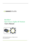
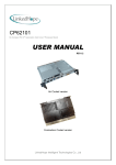
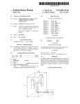
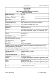
MATEC Web of Conferences 22 , 010 0 8 (2015)
DOI: 10.1051/ m atec conf/ 201 5 2 2010 0 8
C Owned by the authors, published by EDP Sciences, 2015
A Study on Control System Design Based on ARM Sea Target Search
System
Xinwei Lin*
School of Information Engineering, Shanghai Maritime University, Shanghai, China
ABSTRACT: The infrared detector is used for sea target search, which can assist humans in searching suspicious objects at night and under poor visibility conditions, and improving search efficiency. This paper applies
for interrupt and stack technology to solve problems of data losses that may be caused by one-to-many multi-byte
protocol communication. Meanwhile, this paper implements hardware and software design of the system based
on industrial-grade ARM control chip and uC / OS-II embedded operating system. The control system in the sea
target search system is an information exchange and control center of the whole system, which solves the problem of controlling over the shooting angle of the infrared detector in the process of target search. After testing,
the control system operates stably and reliably, and realizes rotation and control functions of the pan/tilt platform
during automatic search, manual search and track.
Keywords:
Target search; one-to-many communication; ARM; uC / OS-II
1 INTRODUCTION
With China’s economic development, the sea transport
is increasingly busy, and the marine traffic safety and
emergency rescue tasks are arduous. Currently, the
domestic search and rescue organization mainly depends on the search and rescue personnel to observe,
search and rescue. However, the ship accidents mostly
occur in bad weather or traffic-intensive conditions,
which may bring great difficulties to search ships and
persons in distress. Under a complex search and rescue environment, it is difficult for the search and rescue personnel to find targets in back light, at night and
in a severe weather [1-3]. The target search system
based on infrared detectors can be used for search and
rescue, which can overcome these shortcomings and
deficiencies [4].
Sea target search system includes an infrared detector, a pan/tilt platform, a target detecting board, a
master control PC and an automatic search control
system. The system structure is shown in Figure 1.
The control system is an information exchange and
control center of the whole target search system. In the
process of target search, the main control PC can control over each function of the system (including automatic detection and tracking of the target, manual
detection and tracking, control of pan / tilt platform
and vertical search range, set of detecting parameters,
and control of the focusing and calibration of the infrared detector).
This paper introduces the hardware structure and
software component of the control system. The circuit
board of the control system is designed and delivered
for production in Altium Designer 8.0. ARM routine
is complied, translated, debugged and downloaded in
ADS 1.2.
Infrared
Detector
Pan/Tilt
Platform
Control
System
Target
Detecting
Board
3&
Figure 1. Structure chart of the target search system
2 RESEARCH OF ONE-TO-MANY SERIAL
PORT COMMUNICATION TECHNOLOGY
The communication of the control system and other
systems adopts communication protocol (each protocol is 7 to 8 bytes) mode. If the way of traditional
software waiting is adopted to receive the entire protocol data, there is a need to take up more CPU time,
and it is likely to cause losses of data sent by other
systems simultaneously. As shown in Figure 2, the
serial port 1 receives data in time 1-3. The routine 1 is
responsible for receiving data on the serial port 1, and
decoding; the serial port 2 receives data in time 2-4,
but causing losses of part of data (Byte1- Byte5) on
the serial port 2 because data receiving time on the
serial port 1 and 2 is overlapping.
*Corresponding author: [email protected]
This is an Open Access article distributed under the terms of the Creative Commons Attribution License 4.0, which permits
unrestricted use, distribution, and reproduction in any medium, provided the original work is properly cited.
Article available at http://www.matec-conferences.org or http://dx.doi.org/10.1051/matecconf/20152201008
MATEC Web of Conferences
high-speed Flash memory, which is enough to meet
the needs of routine memory. LPC2132 has multiple
serial interfaces, including two 16C550 industrial
standard UART, two high-speed I2C interfaces (400
kbit/s), SPITM and SSP. LPC2132 has a Power On
Reset (POR) and Brown Out Detection (BOD) circuit,
which can operate stably within a temperature range
from -40 ° C to 85 ° C. These characteristics can
guarantee that CPU operates stably and reliably under
relatively severe sea environment.
Figure 2. Routine scheduling process of traditional receive
mode
Thus, this paper adopts interrupt function with a
higher priority to receive data on the serial port and
the stack way to timely save communication data, and
then adopts the user routine with a lower priority to
process these data in the time gap in the process of
receiving protocol data, thereby avoiding data losses
during one-to-many communication. After receiving
data on the serial port (COM1 and COM2), the interrupt service routine (ISR 1 and ISR2) will timely stack
data on the serial port, so as to avoid data losses. The
routine scheduling process is shown in Figure 3.
3.1 Serial expansion circuit
Because the system requires three serial ports, but
LPC2132 has only two serial ports, and there is a need
to expand the serial port by the use of serial extension
chip. This paper selects GM8142 expanded serial port.
This chip can expand a standard SPI interface into
four standard UARTs, which is equipped with two
modes of operation: serial expansion mode and
broadcast mode [6]. Serial expansion mode allows all
serial ports to receive and send data by the established
baud rate, frame length and verification mode, as well
as SPI interface. SPI data is 16bit, of which high 8bit
is the address of sub-serial port and additional command and status information, while low 8bit is data
actually sent and received. The serial port expansion
circuit is shown in Figure 4. This paper connects IRQ
interface of GM8142 with EINT1 interface of
LPC2132. When the serial port receives data, the main
control chip can receive the interrupt notification and
timely receive data on the serial port.
3.2 Serial level swithcing circuit
Figure 3. Routine scheduling process after application of
interrupt and stack technology
3 SYSTEM HARDWARE DESIGN
The control system needs to communicate with an
infrared detector, a pan/tilt platform, a target detecting
board and a master control PC. Because the infrared
detector and the pan/tilt platform share a serial port,
the system requires three serial ports. Meanwhile, in
order to ensure that the system operates stably under
severe sea environment, the system requires highly
reliable control chip. Taking into account the design
need of the system, this paper adopts PHILIPS industrial-grade 32-bit microcontroller LPC2132.
LPC2132 is a 32-bit ARM7TDMI-STM CPU that
supports real-time simulation and tracking. On-chip
Real Monitor Software and high-speed tracking execution code can be adopted for real time debugging,
and to facilitate for designing, debugging and downloading routines [5]. LPC2132 can be up to 60 MHz of
working frequency, with 16kB on-chip SRAM, which
can meet the computing needs of control algorithm.
The CPU is equipped with 64kB embedded
The infrared detector and the pan/tilt platform are
placed in a higher position of the ship, relatively distant from the control system, so this paper adopts
RS-422 level standard with a relatively distant transmission distance and relatively high reliability to realize communication between the control system and the
infrared detector and pan/tilt platform. The level
switching circuit is shown in Figure 5 [7]. The communications between the control system and master
control PC and target detecting board adopt RS-232
level standard. The circuit is shown in Figure 6 [8].
4 SYSTEM SOFTWARE DESIGN
In addition to completion of the communication tasks
for the infrared detector, pan/tilt platform, target detecting board and master control PC, transfer tasks for
each function parameter of the system, and control
tasks for the focusing and calibration of the infrared
detectors, the control system shall also complete control tasks for the position of pan/tilt platform under the
automatic search and manual search mode. In order to
complete more complex system function tasks, this
paper adopts uC / OS-II embedded operating system
to achieve scheduling of each task routine by turns [9].
01008-p.2
ICETA 2015
U1
U8
V3.3
20
RXD4
TXD4
RXD3
TXD3
7
8
18
17
GM_RXD4
GM_TXD4
GM_RXD3
GM_TXD3
RXD1
TXD1
RXD2
TXD2
15
14
13
12
GM_RXD1
GM_TXD1
GM_RXD2
GM_TXD2
O1
10K
10K
10K
10K
VDD
SCLK
DIN
DOUT
CS
IRQ
SHDN
RST
GND
GM_SCLK 4
GM_DIN 5
GM_DOUT 6
3
GM_CS
GM_IRQ 11
GM_SHDN16
GM_RST 9
10
O0
R10
R4
R5
R11
GM8142
2
1
V3.3
GM81421 Y2 2
7.3728MHz
C6
22pF
C29
0.1uF
C30
0.1uF
C31
0.1uF
C9
22pF
Figure 4. Serial port expansion circuit
U3
J1
5
9
4
8
3
7
2
6
1
10
11
8
R2
7
120
A
VCC
B
RO
6
5
DI
V5.0
1
2
RXD0
3
TXD0
Z
Y
GND
4
D Connector 9
MAX488
Figure 5. RS-422 level switching circuit
V-
R1 OUT
R2 OUT
T1 OUT
T2 OUT
C2+
C2 -
6
GND
VCC
SP3232
15
2
C10
0.1uF
R1 IN
R2 IN
T1 IN
T2 IN
C1+
C1 -
V+
13
8
11
10
1
3
16
U12
RS232_R1
RS232_R2
GM_TXD2
GM_TXD3
C23
0.1uF
C24
0.1uF
V3.3
Figure 6. RS-232 level switching circuit
01008-p.3
12
9
14
7
4
5
GM_RXD2
GM_RXD3
RS232_T1
RS232_T2
C12
0.1uF
MATEC Web of Conferences
data, while the serial port expanded by GM8142
adopts external interrupt EINT1service routine to
receive data. The process of interrupt service routine is
shown in Figure 7.
OS_ENTER_
CRITICAL()
Y
4.2 Communication subroutine of target detecting
board
Pop down
COM data
Receive data
The communication subroutine of target detecting
board has completed information exchange of the
control system and target detecting board, whose main
task is to receive information related to target search,
command tracking and target position of the target
detecting board, which is used for realization of the
target tracking and delivery of the information of target position to master control PC. The process of the
communication subroutine of target detecting board is
shown in Figure 8.
N
Clear RxIF
OS_EXIT_
CRITICAL()
Figure 7. Interrupt service routine of serial data receiving
TaskUart1Revice
TaskUart0Revice
N
N
New data˛
Y
New data˛
Rcv_new=0
Y
Rcv_new=0
Receive protocol
Rcv_new=1
N
Y Receive protocol
Rcv_new=1
N
N
N
Y
Data
integrity˛
Y
According To the
command to
make the action
Data
integrity˛
Y
Target data?
Task Switch
N
Y
Send target
information to the PC
Switch working
mode
Figure 9. Communication subroutine of the master control
PC
4.3 Communication subroutine of master control PC
Task Switch
Figure 8. Communication subroutine of target detecting
board
4.1 Interrupt service routine of serial data receiving
The built-in serial port of LPC2132 adopts the interrupt service routine of serial port receiving to receive
Master control PC sends data to the control system by
the serial port to control over the rotation of the
pan/tilt platform, and adjust parameters of the infrared
detector and target detecting board. The communication subroutine of the master control PC receives
commands of master control PC and makes appropriate actions, including: control over the rotation direction and speed of the pan/tilt platform; set up target
detection parameters; set up parameters of the infrared
detector; set up the level and vertical rotation range of
01008-p.4
ICETA 2015
TaskUart2Revice
Y
New data˛
N
Rcv_new=0
Y
Receive protocol
Rcv_new=1
N
Rcv_new=1
Y
Parsing received
data , get the current
Angle
N
Y
Auto Tracking
Mode˛
According to the
position, setting next
target position
N
Control level Angle
within ±0.5 degrees
Control vertical Angle
within ±0.5 degrees
update new Angle to
PC
Task Switch
Figure 10. Subroutines of target search and tracking
the pan/tilt platform during automatic search of the
target. The routine flow chart is shown in Figure 9.
4.4 Subroutines of target search and tracking
The control system makes appropriate control over the
motion of the pan/tilt platform according to the location information sent from the pan/tilt platform and
the command received from other systems. For example, when operating in an automatic target search
mode, the control system controls over the pan/tilt
platform to do reciprocating motion within the range
set by the master control PC, so as to search targets
possibly existing in the sea; when operating in a
tracking mode, the control system controls over the
pan/tilt platform to move based on the command of
target detecting board, so as to track targets; when
operating in the master control mode, the control sys-
tem controls over the motion of the pan/tilt platform
based on the command of master control PC, so as to
manually search the target. The flow chart of the subroutines of target search and tracking is shown in Figure 10.
5 SYSTEM TESTING AND RESULTS
5.1 System software and hardware test
1. Prepare basic hardware test routine to test the function and stability of each hardware module;
2. Prepare each subroutine step by step, and carry
out off-line test, that is, to adopt serial debugging terminal routine and simulate each subsystem to send
protocol data, so as to test the function of the routine;
3. Test the reliability and stability of the control
01008-p.5
MATEC Web of Conferences
system software, that is, to adopt serial debugging
terminal routine and simulate each subsystem to send
abnormal and massive protocol data, so as to test the
routine;
4. Connect the control system to the online debugging system software in the target search system, and
adopt the master control PC to test the function of
system.
After a long period of test, the function of the system is normal.
5.2 System object and result
The object of the entire target search system is shown
in Figure 11.
number of offshore ship tests, and the whole system
has carried out performance tests during the day, afternoon and night, and other different environments.
The test results are shown in Figures 12-13. During
target tracking, the control system controls over the
rotation of the pan/tilt platform, and makes the target
located in the center of the screen. Figure 12 shows an
infrared image collected by the system during automatic tracking; during target search, the control system controls over the pan/tilt platform to search suspicious targets on the sea. Figure 12 shows an infrared
image collected during target search. After an overall
test of the system, the function of the control system is
basically realized, and the system performance is reliable and its operation is stable.
Figure 13. Infrared images during target search
6 CONCLUSION
Figure 11. System object diagram
This paper proposes a kind of hardware and software
design method to avoid communication data losses
during one-to-many protocol communication based on
the features of ARM chip selected, and a kind of
method to control over the pan/tilt platform during
automatic target tracking and search, and finally successfully realizes a control system based on the sea
target search system with ARM chip. Compared with
the control system based on other platforms, the control system based on ARM shortens the development
cycle, and gives full play to its high reliability, small
size, flexible application and other characteristics.
REFERENCES
Figure 12. Infrared image during automatic tracking
In this paper, the control system has carried out a
[1] Shi, Chaojian, Kaiyu Xu, Peng Jing. & Ren Lei. 2008.
Architecture of vision enhancement system for maritime
search and rescue, Proceedings of the 8th International
Conference on Intelligent Transport System Telecommunications (ITST2008).
[2] Sumimoto, T., Kuramoto, K., Okada, S., Miyauchi, H.,
Imade, M, Yamamoto, H. & Kunishi, T. 1994. Machine
vision for detection of the rescue target in the marine
01008-p.6
ICETA 2015
[3]
[4]
[5]
[6]
[7]
[8]
[9]
casualty, Proceedings of Industrial Electronics, Control
and Instrumentation. pp: 723-726.
Lin Yiping, Shen Yijun. & Xu Kaiyu. 2009. Research of
Infrared Radiation Characteristics of Small Targets in a
Complex Marine Environment and Image Simulation.
Infrared.
Shi Zhaojia. & Xu Kaiyu. 2007. Visual Enhancement
System of Maritime Search and Rescue. Fourth China
International Rescue & Salvage Forum Proceedings, pp:
48-52
Guangzhou Zhou Ligong MCU Development Co., Ltd.
LPC2131 / 2132/2138 User Manual.
Chengdu Guoteng Microelectronics Co., Ltd. GM8141 /
GM8142 Data Sheet of UART Extended Chip Compatible with SPI Bus.
Maxim Integrated. ±15kV ESD Protected, Slew Rate
Limited, Low Power, RS-485/RS-422 Transceivers Data
sheet.
Sipex Corporation. SP3222E/3232E Datasheet.
Jean J. Labrosse. 2007. Embedded Real-time Operating
System, uC / OS-II. Beijing: Press of Beijing University
of Aeronautics and Astronautics.
01008-p.7