1
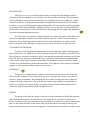
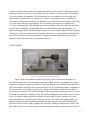
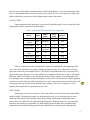
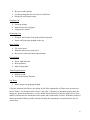
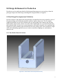
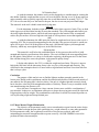
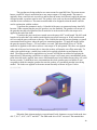
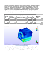
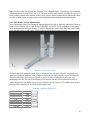
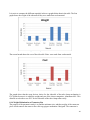
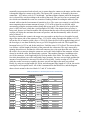
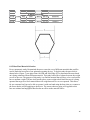
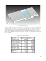
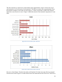
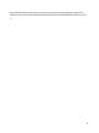
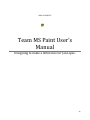
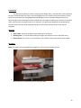
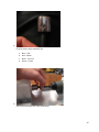
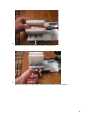
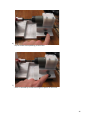
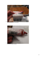
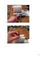
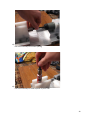
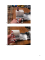
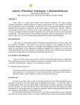
Team MS
Paint
User’s
Manual
June 1
2010
Team MS Paint spent the 2009-2010 school year designing and
manufacturing a paint tube opener for Jan Lipes. Jan is a retired
surgeon who lives in Doylestown, Pennsylvania. He was diagnosed
with multiple sclerosis and was forced to retire. Having lost the use of
his right arm and being confined to a wheel chair, Jan is unable to
create sufficient grip and torque to open his oil based paint tubes.
Team MS Paint designed a horizontal sitting device which is
operational using one hand. This allows Jan to be able to be more self
sufficient in his work and no longer rely on others to be able to get his
work done.
Designing to
make a
difference for
Jan Lipes.
BACKGROUND
Jan Lipes was a very successful surgeon until he was diagnosed with multiple sclerosis.
After this his life was changed, he was forced to retire from his life of medicine. This did not stop
Jan from blazing his own path. Jan retook to his love of painting after he was confined to a wheel
chair and lost the use of his dominant right hand. He taught himself to paint with his left and has
become a very successful Pennsylvania impressionist painter. He has been able to sell his paintings
for upwards of three thousand dollars, which has become a source of income in his household. He
faced troubles in not being able to be self sufficient in his painting and has sought many methods to
keep from becoming dependent on others.
The University of Connecticut designed and built Jan a paint tube opener to help him in his
journey for independence but this device did not perform up to Jan’s needs. Team MS paint was
informed of Jan’s situation through Dr. Hallowell. The team decided this was a project worth
pursuing and took on the challenge of trying to design to make a difference in Jan Lipes’ Life.
STATEMENT OF PROBLEM
The device to be designed and manufactured for Jan needed to be capable of opening paint
tubes whether they were brand new or if they had been mostly used. The primary need of the device
directly from Jan was that it needed to be able to open partially opened tubes when they had a dried
paint seal. This was the primary problem that Jan’s current device had and was something that he
always had to ask for help to be able to accomplish. The design also needed to be able to operate
with the use of one hand since Jan has limited mobility in his right arm. These things all combined
together to create a unique problem which was to be solved.
RATIONALE
This project was chosen because without a functioning paint tube opener the client is not
able to provide for himself. After retiring from his career as a surgeon the client’s new source of
income is selling his paintings. In his disabled state he is unable to open paint tubes by himself,
relying on the help of others to be able to do his job, which is unacceptable. By making him an
opener, we will allow the client to become self-reliant in his profession, allowing him to lead a
normal life without being held back by his multiple sclerosis.
DESIGN
The design of the paint tube opener was based on a self centering vise to hold the paint tube
and a small motor to remove the paint tube cap. The design for the cap removal came from an
electric screwdriver. The motor from the electric screwdriver was encased in a special motor mount
that was designed to hold the electric motor while not needing the old screwdriver housing. The
motor mount drawing can be found in the appendix. The motor mount assembly was coupled to the
1
original screwdriver head to utilize the original gearing of the screwdriver. To keep the paint tube
stationary during cap removal a self centering vise was designed. A drawing of the self centering
vise can be found in the appendix. The self centering vise was designed with a screw that had
opposite direction threads on it to cause the vise to move in towards the center. A standard vise
could not be used because as different size paint tubes were used the distance from the center of the
vise to the edge of the tube would change. The vise and the motor mount were mounted on a
5”x12”x1” aluminum plate. The aluminum plate was used because the extra weight was needed to
keep the opener stationary. The aluminum plate also added aesthetic appeal to the opener. An
open/closed toggle switch was added and the motor was wired up to the original screwdriver battery
and charger. Using the original battery and charger allowed us to use the original wiring setup and
not need to design our own wiring schematics. Using the original components also gives us the
option to easily replace the battery if it becomes defective.
DEVELOPMENT
Figure 1: Constructed Paint Tube Opener Prototype
Figure 1 depicts the complete constructed prototype. 6061 Aluminum and plastic were
selected to build the device for their light weight and strength. The base was milled out to reduce
weight as decided by our initial specifications. The base footprint was reduced from the initial size
after considerations were taken for the motor and tube vise. The rechargeable battery configuration
for the screwdriver motor helps solve the power failure and also adds a portable feature that was
previously not considered. The on/off switch has a light on it to indicate when the power is on, also
the sound of the motor is a warning as well. The internal gearing that came with the driver was kept
since it is a durable design and provides plenty of torque output. In order to grip the cap, it was
discovered that basic 12-point sockets do the job with ease. Not only do they tightly grip the cap,
but they minimize the wear and thus the likelihood of destroying the caps. Also, different sized
paint tubes can be used by simply changing the socket size, making the opener more versatile. The
tube holder itself is a vise, made to open well beyond the largest tube the client uses and to close to
2
meet the sizes of the smaller used tubes that he rolls from the bottom. In overall construction of the
device, a left-handed theme was kept to cater to Jan’s needs. The base of the opener is coated with
rubber to hinder the entire device from sliding around on his work surface.
EVALUATION
Upon completion of the prototype, it was tested by both the group, to see if it met the initial
design specifications, and Jan for client feedback.
Table 1: Initial and Final Specification comparison
mL
Initial
Value
37-500
Final
Value
37-500
in-lb
unknown
3.5
YES
ft
< 10
<
12x24x36
5
YES
5x12x4.5
YES
Metric
Units
Tube Size
Torque
Needed
Cord Length
Device Size
in
Unscrew
Time
Set up Time
Weight
Device Life
Success?
YES
sec
< 10
3
YES
min
lb
years
<1
< 50
> 10
<1
<10
?
YES
YES
Table 2 compares the initial specifications, which were established at the beginning of the
year, to the final values that were analyzed during prototype testing. It is evident that each of the
specs has been met by the completed device. The client’s requirements that were expressed to the
group at the start of the project were also addressed. According to Jan the device had to: Open half
full tubes, Open 37 mL tubes, be one handed operational, Easy to operate, Low maintenance, and
Low strength. After visiting Jan and watching him use the device and express his complete approval
it is safe to say that each one of his requirements were met. A quote taken from an email sent by Jan
to the group sums up his satisfaction with the opener stating, “The device is ingenious, works
perfectly for me and will be a great assist in my work.”
DISCUSSION
This project met all of its objectives. The client is able to use it with ease and is thoroughly
satisfied with it. The paint tube opener can open multiple sized, is very quick and easy to setup,
opens the tubes quickly and efficiently and is fully portable with backup rechargeable battery
power. We were within all of the original design parameters. While the project is very unique the
team does not feel that it is patentable, we did not really design anything new, instead drawing
inspiration from multiple already produced items. While there are many people suffering from
3
symptoms and restrictions similar to Jan’s the team feels that there is not a large enough market for
this project to be made in mass numbers or marketed to the public. If this project was to be redone it
would be better if the drip tray was positioned better and also much cheaper if the vise screw only
needed to be made once instead of three times. Other than this we feel that the project is an
outstanding success and are all very pleased with the end results achieved.
REFERENCES AND ACKNOWLEDGEMENTS
Special Thanks to Randy Mulford for his assistance and guidance in the manufacturing process
4
APPENDIX
7.1 FMEA
To begin, there were eight possible modes of failure that needed to be addressed in order to
guarantee the success of the opener. These modes were then rated using the system provided in the
SrD WebBook, by evaluating the severity, occurrence, and detectability. On a scale of 1 – 10 for
each characteristic with 10 being the worse case, each mode was rated. Then possible solutions to
these failure modes were discussed and used to reevaluate them in an attempt to lower their ratings.
The results of this analysis are shown below.
Table 2: FMEA for the eight modes of failure
Modes of Failure
Severity
Occurrence
Dectecability
Totals
Motor
Torguing out
Before After
9
9
6
3
7
5
378
135
Gear Failure
Before After
9
9
3.5
2
8
8
252
144
Severity
Occurrence
Dectecability
Totals
Motor Failure
Before After
9
9
3
2
7
7
189
126
Power Failure
Before After
7
5
3
3
7
1
147
15
Gripping Cap
Before
After
9
9
2.5
1.5
2
2
45
27
Turn Wrong
Direction
Before
After
4
4
2
1
2
1
16
4
Destroying
Cap
Before After
4
3
3
2
2
2
24
12
Cap Wear
Before After
2.5
2
4
4
2
2
20
16
Solutions
Motor Torquing Out
•
•
•
Simulate dried paint on threads and test torque needed to remove cap
Design with a factor of safety of 2-3
Test the prototype on caps that have been stuck on with dried paint
Gear Failure
5
•
•
•
Buy a pre-made gearbox
Use the gearing from the screwdriver if sufficient
Design for much larger torque
Gripping Cap
•
•
•
Prototype testing
Material selection of gripper
Grip pressure control
Destroying Cap
•
•
Design to the lifetime of the paint of tube being used
Ensure sufficient grip strength on the cap
Motor Failure
•
•
•
Use a new motor
Eliminate unnecessary spin cycles
Buy a motor with more than required torque
Power Failure
•
•
•
Power Light indicator
Back-up battery
Make rechargeable
Turn Wrong Direction
•
•
Indicator Light
Lock in the correct direction
Cap Wear
•
Ensure proper cap gripping strength
Using the solutions listed above, the ratings for all of the eight modes of failure were decreased as
seen in Table 1, for the totals of the “before” and “after” columns. It is important to know that, the
ratings of 9 do not mean that this is a severe health hazard. Instead, for the sake of this device, they
stand for failures that are detrimental to the opener and would render it useless. With these modes of
failure on the table and the possible solutions at hand, the experiments were performed to test for
critical data.
6
8.0 Design Refinement for Production
Provide an overview and some details of the design refinement process you used to go from the
prototype design to the final design, including how design methods were applied.
8.1 Final Design Development and Validation
In order to improve and optimize the design initially conceptualized, the team created five areas of
the project design, and conducted parametric studies to improve these areas. The five studies
conducted included one test each to minimize the size and weight of the connector bar, the tube
holder and the motor mount, and one test each to find a lightweight, low cost material for the base
plate and tube holder. In each case, several geometries, sizes and/or materials were considered and
compared, in order to find the most efficient selection. The primary goals were to minimize weight
while still withstanding applicable stresses in order to minimize shipping cost, and minimize
material costs.
8.1.1 Tube Holder Material Selection
Figure 8.1.1: Tube Holder used in this parametric study
7
For the parametric study, a weight versus cost analysis was performed on the tube holder
pictured above. The part stands 3.5” tall, 3.0” wide and 6.5” long with the obvious cut outs and
holes. Further thin walling would not be necessary considering the amount of material that has been
removed already. The main reasons that this topic was chosen for this analysis are because this is
being created for a client with use of only one hand. He should be able to move it if need be without
straining himself. Also, the unit will be sitting on top of a table, so too much weight could do
damage to it. Finally, it doesn’t make practical sense for this part to be heavy or bulky. Its purpose
is to hold a paint tube with the help of a V jaw, so it will not be seeing a ridiculous amount of torque
or stress.
For this study, the variable parameter is the material, while the constant constraint is the
part itself. Basically, six different materials were selected for the part and their characteristics were
analyzed using Algor and Solid Edge. Then, with the dimensions needed as well as the material
type, McMaster-Carr was used to find the cost of the stock needed to make the part.
The most difficult part of this study was trying to find the correct sized stock on McMaster-Carr that
could be used to manufacture the part. For the purpose of this study, the part was broken up into
three parts; the two walls at the full height of 3.5’’ and the center section whose dimensions are
1.5’’ thick, 2’’ wide, and 6.5’’ long.
The most important variable in this study is the weight of the part. As a guideline, the part should be
less than 5 lb and the cost should be less than $60. These are high values but it provides some
leeway in the material selection. The yield strength and modulus of elasticity will be taken into
account when making the final decision as well. Table 1 below shows the results from the study in
no specific order.
Table 8.1.1: Parametric Weight vs. Cost Results
Material
Density
(lb/in³)
Al 6061-T6
9.80E-02
1.00E+07
ABS Medium Impact Plastic
3.70E-02
Polypropylene, General Purpose
Modulus of Elasticity Yield Strength
(psi)
(psi)
Weight
(lb)
Total Cost
4.00E+04
3.71
$54.28
3.30E+05
6.30E+03
1.40
$58.69
3.30E-02
1.60E+05
4.80E+03
1.25
$17.21
PVC
5.00E-02
400
1.00E+03
1.89
$39.44
303 Stainless Steel
0.29
2.80E+07
3.70E+04
10.97
$271.86
Unalloyed Titanium
0.16
1.49E+07
2.50E+04
6.17
N/A
Titanium
First off, the titanium was immediately thrown out of the running since the cost of the stock
could not be determined. In order to keep the study fair, McMaster was the only company used to
find the material cost, and they did not have the sizes needed to complete the study for titanium.
However from experience, the titanium would be very expensive, and way beyond the $60 limit.
8
303 Stainless Steel
As with the titanium, the stainless steel was also dropped as a consideration for creating the
tube holder. Both the weight and the cost are well over the limits. Having over a 10 lb part amiss an
entire assembly adds up quickly especially since the overall dimensions are around 5”x12”x7”. The
$271.86 cost was not only over the limit for the part, but also is near our projected final budget.
This material, in the end, is highly impractical for this part.
6061-T6
For the aluminum, both the weight and cost are below their respective limits. They are both
in the upper area of their limits but they do meet the standards. The yield strength and elasticity are
obviously higher than the plastics, which do add some appeal to the material. But, as mentioned
earlier, they do not have to be too high since the loads it will experience are not that significant.
ABS
As with the aluminum, the ABS meets the limits for weight and cost, however the cost is a
surprising $58. This is somewhat unappealing for the fact that if the part was to break it would cost
quite a bit to get it fixed. Of all the plastics in the study, ABS has the highest yield strength and
elasticity, which may outweigh the high cost, in the final decision.
Polypropylene
This material is well below the established limits. It also possesses the mid level yield
strength and elasticity specifications of the plastics. The cost is definitely the most appealing factor
for this plastic. Being that it is so cheap, it would make replacing a broken part nicer for the client.
But with that cheap price comes the question, is the material quality cheap?
PVC
Like the other plastics, the PVC is within the weight and cost limits. The price is not too
high in the $60 limit, but the interesting factor is the very low yield strength and elasticity. This
could lead to the assumption that it is a more brittle or rigid material and won’t have that little flex
that is always a plus.
Conclusion
The purpose of this analysis was to find the lightest, medium strength, material at the
lowest price. Based on this requirement, and the idea that the tube holder would be made entirely of
one material, the Polypropylene is the best choice. Not only is it lightweight and extremely cheap,
but it does have a decent yield strength and modulus of elasticity. Plastic is easy to machine which
cuts manufacturing time down as well.
On a side note, if strength was a large concern a better route would be a combination of
two materials. In that case, an aluminum center piece to house the moving parts would be ideal with
Polypropylene walls for weight. This combination would allow for all the best material qualities as
well as providing a light and cheap finished part.
8.1.2 Motor Mount Weight Minimization
The objective of the parametric study was to test and analyze a part from the senior design
project and then redesign the part while optimizing size, weight, material, or some other parameter.
For this parametric study, the weight and overall size of the part was reduced, while still
maintaining the structural strength needed to operate correctly. ALGOR FEMPRO was used to
perform the finite element analysis.
9
The part that was being studied was a motor mount for team MS Paint. The motor mount
houses a small DC electric motor that has a max torque output of 20 inch pounds. The motor is
originally from a small electric screwdriver and because the motor itself doesn’t supply the amount
of torque needed, a gearbox must be used. The gearbox to be used was the one that originally came
with the electric screwdriver. The motor mount needed to be designed so that the motor could be
used in conjunction with the gearbox.
To perform the parametric study, a 3d model of the part was constructed using AutoCAD
Inventor. When constructing the part, the gear box was also modeled. The gearbox was not one of
the parts that needed to be optimized, but it needed to be in the model to allow the torque to be
applied at the end of the shaft.
To analyze the part a mesh was created across the part at 0.05” mesh length. The 0.05 mesh
length was because that is the smallest mesh that the part would converge at. If any smaller mesh
size was used the part would seem to diverge. This could be because the part was putting very small
concentrated loads in places where the part was constrained together. To apply the torque load to
the part, the equation Torque = 2*Force*radius, was used. This showed that a force of 3.86 lbf
needed to be applied to each side to achieve a net torque of 20 inch pounds. This force was applied
at the end of the gear box because this is where the gearbox will turn the cap off the paint tube. To
achieve the applied torque, a nodal force needed to be applied at both the top and bottom of the
shaft. The torque needed to be applied this way because ALGOR has no method of applying the
torque directly. When using a nodal force to apply a torque it will create stress concentrations at the
point where the load is applied, these stress concentrations need to be hidden because they will yield
incorrect results. To hide these stress concentrations the whole gearbox part was hidden. It was
acceptable to hide the complete gearbox because the gearbox is a purchased part that is not being
studied. The loads were applied to the motor mount assembly as shown in figure 1 below.
Figure 8.1.1: Motor mount design
When the finite element analysis was performed, brick elements were used with mesh sizes
of 0.2”, 0.15”, 0.10”, 0.075” and 0.05”. The final mesh size of 0.05” was used. The material that
10
was used to manufacture the motor mount was Low Density Polyethylene. This material was chosen
because it was already available, it’s light, strong, and it is suitable for our needs. Using a mesh
length of 0.05” showed the von Mises stress at 3.279 lbf/(in2) for the original motor mount. This
stress yielded a minimum safety factor of 487.5. This means that the part is extremely overdesigned
and that there is room for thin walling the part and creating cutaways. The results for each of the
different mesh sizes on the original motor mount are shown in table 1 below. The von Mises
stresses of the original part are shown below in figure 2.
Table 8.1.2: Stress vs. mesh size for motor mount
Parametric Study of Original Part
Mesh Size
(in)
Tresca*2
Min. Safety
Stress lbf/(in^2) von Mises Stress (lbf/(in^2)) Total Nodes DOF
Factor
0.2
1.804
1.626
4664 13596
885.6
0.15
1.797
1.668
7350 21372
934.8
0.1
1.985
1.786
16058
46725
886.2
0.075
0.05
2.776
3.685
2.431
3.279
94725
32415
99504 292977
641
487.5
Figure 8.1.3: Modified motor mount design
The new modified motor mount was changed by thin walling the top and bottom of the part
and removing 0.1” of material. The sides of the mount had cutaways put into both sides. The
cutaways on the sides will help with both weight and improve airflow allowing the motor to cool
more easily. The modified motor mount also had .1875” of material removed from the end of the
11
mount. An engineering drawing of both the original and the modified motor mount are included in
the end of this section.
When the finite element analysis was performed on the modified motor mount, a mesh size
of 0.05 was again used. The max von mises stress was found to be 3.334 lbf/in2. This gave a
minimum factor of safety of 479.32. This factor of safety is still extremely over engineered, but size
restrictions and manufacturing methods limit what else can be done to the part. In table 2 below the
tresca and von Mises stresses are all shown for the various mesh sizes on the modified part. Figure 3
below shows the von Mises stresses for the modified part.
Table 8.1.3: Stress vs. mesh size for new motor mount design
Parametric Study of Modified Part
Mesh
Size (in)
Tresca*2
Stress (lbf/(in^2)) von Mises Stress (lbf/(in^2))
Total Nodes DOF
Min. Safety Factor
0.2
2.922
2.735
3419
1146
742.8
0.15
2.453
2.377
6330 18447
673
0.1
0.075
0.05
2.716
3.113
3.453
2.716
3.006
3.334
46002
15673
29644 87270
94330 279372
548.1
531.5
479.32
Figure 8.1.4: Final motor mount design
The weight saving of the modified part to the original part was 1.071oz. This is a small
amount of weight savings, but about 28% weight reduction. Another benefit to the design of the
modified part is that it allows airflow to the motor keeping it cool. Cooling the motor is not a major
concern because it will not run for extended periods of time; however it is an added benefit to the
new design. The max von Mises stress for the new part was 3.334 lbf/in2, this value was only 5%
12
larger of a stress than the original part. The part is far within the limits of it breaking or permanently
deforming and has a safety factor of 479.32. The part could be made smaller, but there is not a lot of
room to remove much more material. If the screws weren’t in there and the motor pins weren’t there
it would be much easier to remove more material and the mount could be made much smaller.
8.1.3 Tube Holder Weight Minimization
For my parametric study I am finding the lightest material possible to make the sidewalls of the tube
clamp, pictured below, out of while being as affordable as possible. Each component of the opener
has to be maximized in weight because we will be shipping this opener back and forth between our
client Jan and ourselves and cannot afford to ship an opener that weighs too much.
Figure 8.1.5: Tube holder assembly
To figure this relationship out I used Algor to determine how much the sidewalls weighed being
made out of different materials, then I went to mastercraft.com and found the cost of the materials.
The sidewalls need to be made out of metal or plastic for easy cleaning and to allow for easy
machining in the lab. The cost of machining is not factored into the costs of material because we
will be doing all the machining ourselves and will not be paying ourselves. The table below shows a
list of possible materials, the materials weight and the cost.
Table 8.1.3: Material weight and cost
Material
Weight (lbs) Cost ($)
Aluminum 6061
3.86
57.71
Aluminum 2024
3.98
81.44
PVC
1.87
26.64
Stainless Steel 303 11.32
290.12
Stainless Steel 309 11.44
54.16
Titanium
6.44
223.09
13
It is easier to compare the different materials in the two graphs below than in the table. The first
graph shows the weight of the sidewalls if they were made from each material.
Figure 8.1.6: Weight of Sidewalls of Each Material
The second graph shows the cost of the sidewalls if they were made from each material.
Figure 8.1.7: Cost of Sidewalls of Each Material
The graphs show that the most obvious choice for the sidewalls of the tube clamp mechanism is
PVC plastic because it is at half the weight and cost of the closest competitor, Aluminum 6061. This
allowed us to decide to use PVC for the sidewalls of the tube clamp rather easily.
8.1.4 Weight Minimization of Connector Bar
The purpose of the parametric study is to find the minimum size, and thus weight, of the connector
piece which connects the motor to the collet cap gripper mechanism I designed. The connector is
14
essentially two protrusions back-to-back, one is square shaped to connect to the motor, and the other
is hexagonal shaped to connect to the collet. The square side’s geometry is dictated by the motor
connection – 0.25 inches a side, 0.075 inch depth – and thus remains constant, while the hexagonal
size is what will be varied according to the results of the study. The goal is to have a geometry and
size which can withstand the worst case scenario of loading without exceeding the material yield
strength, while using the least amount of material to do so. The worst case scenario is would be the
motor outputting the maximum amount of torque, 15.12 in*lb as found by our 488 lab, while
encountering complete resistance and not being able to turn at all. The material to be used for this
piece is AISI 1010 steel, which has a yield strength of 305 MPa. Note that no factor of safety is
being used, because we found in another 488 experiment that the tube will twist and be destroyed at
a torque well below the maximum the motor can produce, and thus that naturally adds a factor of
safety of about 2.5.
In order to simulate this scenario, the torque was converted to an edge force to be applied to each
edge of the square side of the connector. Thus, 15.12 in*lb, with a perpendicular distance of 0.125
in from the axis of rotation yields a force of 120.96 lb. Since the force will be applied along each of
the four edges, it was then divided by four to get 30.24 lb applied to each side. The length of the
hexagonal piece is 0.25 in, and for the initial test, I held the outer 0.125 in fixed. The reason for this
is as follows: call the length of the body of the paint tube the x-direction. The cap is removed by
spinning about this axis, and thus the collet and connector piece also spin about this axis. However,
the collet is free to traverse along the connector, and so the whole length of the connector will not
always be inside the collet, but instead only a portion. Thus another parameter, in addition to the
size of the connector, is the length which is to be kept inside of the collet. The results of the first
few trials showed that even with a sufficiently large geometry, the stress was too high, and thus the
amount of overlap had to be increased. For the next set of trials, I set the overlap to 0.175 in, and
while the results were more acceptable, the stress was still too high as the mesh was refined.
Finally, by using an overlap length of 0.200 in, and a hexagonal edge length of 0.150 in, the results
converged to an acceptable stress. All of this is summarized in the table below, and the diagram
shows what is meant by the sizes labeled “a” and “b” in the table.
Table 8.1.4: Stress vs. mesh and part size for connector bar
Size
Mesh
a (in) b (in) (in)
0.100
0.100
0.125
0.125
0.135
0.135
0.200 0.01
0.200 0.005
0.250 0.01
0.250 0.005
0.270 0.01
0.270 0.005
0.135 0.270 0.01
0.135 0.270 0.005
0.150 0.300 0.01
Parametric Results
Elements
Stress
(#)
(psi)
(MPa)
0.125 in constrained
1460
30944 213.35
6218
44225 304.92
1669
36447 251.29
6964
41901 288.90
1753
29871 205.95
7283
41315 284.86
0.175 in constrained
1753
29923 206.31
7283
37138 256.06
1907
31746 218.88
Displacement
(in)
0.000132
0.000135
0.000127
0.00013
0.000123
0.000126
0.000123
0.000126
0.000116
15
0.150 0.300 0.005
0.150 0.300 0.01
0.150 0.300 0.005
0.150 0.300 0.003
7904
37454 258.24
0.200 in constrained
1907
28455 196.19
7904
37651 259.59
21800
39420 271.79
0.000119
0.000116
0.000119
0.00012
Figure 8.1.8: Connector bar dimensions
8.1.5 Base Plate Material Selection
For my parametric study I determined the mass versus the cost of different materials that could be
used to make the base plate of our paint tube opening devices. To do this study the part which is
shown below (Figure 1) was placed into ALGOR and Solid Edge ST2 to determine the mass based
on it being constructed from different materials. This study looked for a balance between the weight
as well as the cost. The purpose of this study is to find the material that will have a low cost but also
have a medium weight. The base itself needs to have some weight to hold itself down as it is being
operated the target is to find a material that will weigh between five to seven pounds. This allows
for our customer Jan Lipes to be able to operate it with one hand using the base plate as a counter to
the forces that he will be applying to the device. The stresses that are going to be applied to this
base are minimal and negligible therefore has no effect on the material choice.
16
Figure 8.1.9: Base plate design
Table 1 below shows the mass as well as the prices for the materials to be purchased to manufacture
the base plate. The prices below show what the cost would be to purchase the raw material before it
would be manufactured. In the case of this project the machine time does not cost us any actual
money value so that time was not calculated into the cost analysis. If machining costs were to be
included in our budget that would change many of the values but all would be increased based upon
their machinability.
Table 8.1.5: Mass and Cost of Materials
17
The data is shown in a much more visual manner in the graphs below. Figure 1 shows the cost of
each material as well as the mass of each material. This allows a much easier representation of how
the materials compare to each other in each category. A cherry would base would be the cheapest
material to create our device out of. Figure 3 shows the masses of the materials comparative to each
other.
Figure 8.1.10: Cost of base plate materials
Figure 8.1.11: Mass of base plate materials
We can see from Figure 3 that the four makes of Aluminum fit in the mass range that was targeted.
We then refer back to Figure 2 to find which of these four materials has the lowest cost. This tells us
18
that Aluminum 6061 has the lowest cost of the four materials in the targeted mass range. This
allows for our selection of the material Aluminum 6061 to be used to manufacture our base plate.
13
19
Section 9.2
Manufacturing Costs
The paint tube opener was designed with the plan of only manufacturing one device. The
cost report was created with the idea that only one paint tube opener was going to be created. In
Table 9.1.1 below, a breakdown of total time, labor/overhead cost, material cost and total cost can
be seen. To determine these costs, the operation to create each sub assembly was analyzed. We then
determined the amount of time that was necessary to perform each operation. Based on the technical
difficulty of the task, operation labor and overhead costs were added to the cost.
Table 9.1.1 Manufacturing Cost and Time
Sub Assembly
Motor Mount
Vise
Baseplate
Riser Block and
Battery Cover
Screwdriver
Motor and
Hardware
Whole
Assembly
Total Time
6.35
9.8
4.5
9
Labor/Overhead Material Cost
Cost
230
20
443
45
235
45
311.25
15
Total Cost
304
488
280
326.25
1
12
65
77
30.65
1231.25
190
1421.25
The most expensive part of the paint tube opener to create was the vise. The vise was the
most expensive because it had the most material in it and it had a large amount of machining
involved in it. In order to reduce some of the costs of manufacturing the vise, the vise was designed
with the minimal amount of work needed to create it. The mounting block on the ends and both of
the moving jaws on the vise were both made from ½’ x 1’ aluminum square stock. This eased
production because the bar only then needed to be cut to length, drilled and tapped. Since we used
this method for the lower bars on the vise, upper paddles needed to be constructed for the jaws. This
method allowed us to use different materials on the jaws and to save money by only having one size
of material to buy for the lower jaws.
Another way that we saved money was by utilizing the parts from an electric screwdriver.
The gearbox, driver, electric motor, and battery were all used from the electric screwdriver. A
different motor mount housing was created to mount the motor in because there was no need to
have the complete old screwdriver housing mounted on the paint tube opener. The device was
powered using the battery from the original screwdriver. This eliminated the need to find a different
power supply and deal with extra wiring. Using the parts from this electric screwdriver saved a
20
large amount of time because of the various design and manufacturing that had already been done to
create the screwdriver.
Design for Manufacturability
If the paint tube opener was going to be manufactured on a large scale, there are some things
that would be designed differently. The first major change would be to make the base plate out of a
type of plastic that could be injection molded. The injection molding would cut down on a large
amount of manufacturing time because there would be virtually no machining to do. The base plate
could also be molded directly onto the riser plate eliminating the need for another part. The motor
mount is already made of plastic and could be easily molded eliminating more machining time.
Adhesives could be used to secure the various parts together rather than bolts. A different design of
a self-centering clamping mechanism would also facilitate a quicker and easier manufacturing
process.
21
OHIO UNIVERSITY
Team MS Paint User’s
Manual
Designing to make a difference for Jan Lipes.
22
Introduction:
This device was made by the Ohio University Senior Design Team, Team MS Paint. It was created for
the artist named Jan Lipes. Jan Lipes is a retired surgeon who lives in Bucks County, Pennsylvania. He was
forced into retirement after being diagnosed with Multiple Scyrosis, eventually losing the used of his
dominant right hand and being confined to a wheel chair. He taught himself how to paint with his left hand
and is now pursuing a successful career as an oil painter. This opener was designed to be operated with
only one hand so that Jan could independently open his paint tubes and pursue his career without
assistance.
Warnings:
•
•
•
Pinch points – be aware of fingers when tightening or loosing vise
Rotating parts – be sure all loose clothing can fingers are away from motor shaft when using
Electric shock – do not use in or around water, risk of electric shock, electrocution and/or death
Directions:
Note: This device can be operated while plugged in or while running on battery power
1)
Be sure that vise is sufficiently open for your paint tube
23
2)
Find the proper socket assembly size:
a.
b.
c.
d.
3)
Blue – 5/8”
Red – 18 mm
Black – 14.5 mm
Green – 14 mm
Place socket assembly into motor attachment
24
4)
5)
Place paint tube cap in socket, allowing socket to hold tube up
Tighten vise allowing a snug enough contact with paint tube to prevent rotation
25
6)
7)
Flip the rocker switch powering on the motor
After 2-5 seconds flip rocker switch again to power off the motor
26
8)
9)
Release the paint tube from device
Place paint needed on palate
27
10)
11)
Tighten vise 2-5 turns
Slide paint tube into vise vertically, with threads on top
28
12)
13)
Pull socket assembly from motor opening
Use socket assembly to screw cap back on paint tube
29
14)
15)
Loosen vise
Remove paint tube
30
Suggested Maintenance Schedule and Instructions:
•
•
•
Be sure to recharge the battery after every couple of weeks of use or if the motor struggles opening
paint tubes.
Wipe excess paint out of sockets
If battery no longer holds a charge it can be replaced , see “Replace Battery” and “Replacement
Parts Information” sections
Replace Battery:
1.
2.
3.
4.
Unscrew battery cover
Disconnect slide attachment points of wires on battery
Reconnect wires to new battery
Replace cover and screws
Troubleshooting and Service Instructions:
•
•
If socket slips without opening tube, try smaller socket
If opener doesn’t run when switch is activated check plug or try plugging into the wall
Replacement Parts Information
•
Replacement battery: DeWALT 497755-01
31