1
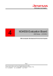
EFP-LC
Instruction
Manual
4th Edition
SUISEI ELECTRONICS SYSTEM CO., LTD.
Thank you for choosing EFP-LC.
If you have any inquiry regarding the product, please contact us or our sales agency.
For your information, the content of this manual may change without prior notice.
Please check our website for the latest information;
http://suisei.co.jp.
Index
Preparation for Safty ............................................................................ 4
Please read this part first. .................................................................... 5
1.
Preparation needed to start using EFP-LC................................. 6
1.1 CHECK CONTENT IN A PACKAGE AND ACCESSORIES ............................................................................................................6
1.2 OPERATION ENVIRONMENT ......................................................................................................................................................6
1.3 NAME OF EACH PART OF THE PRODUCT .................................................................................................................................7
1.4 HOW TO CONNECT .....................................................................................................................................................................9
2.
To operate EFP-LC...................................................................... 10
2.1 TO INSTALL CONTROL SOFTWARE ....................................................................................................................................... 10
2.2 TO WRITE IN DATA ................................................................................................................................................................. 10
STEP 1 CREATION OF USER PROGRAM (HEX/MOT) AND SCRIPT FILE (PBT) ................................................................ 11
<SCRIPT COMMAND WHICH CAN BE USED IN PBT FILE> ..................................................................................................... 16
■ERASE COMMAND ....................................................................................................................................................................... 18
■BLOCK ERASE COMMAND ......................................................................................................................................................... 19
■READ COMMAND ........................................................................................................................................................................ 20
■BLANK CHECK COMMAND ........................................................................................................................................................ 21
■HIGH-SPEED BLANK COMMAND ............................................................................................................................................... 22
■ALL BLOCK BLANK CHECK COMMAND ................................................................................................................................... 23
■VERIFY COMMAND ..................................................................................................................................................................... 24
■HIGH-SPEED VERIFY COMMAND .............................................................................................................................................. 25
■PROGRAM COMMAND ................................................................................................................................................................ 26
■LOCK BIT COMMAND.................................................................................................................................................................. 27
■ID VERIFICATION COMMAND .................................................................................................................................................... 28
■MCU SET COMMAND ................................................................................................................................................................. 30
■READ PROTECTING COMMAND................................................................................................................................................. 32
■WAIT COMMAND ......................................................................................................................................................................... 33
■VDD SUPPLY COMMAND ........................................................................................................................................................... 34
■BAUDRATE SET COMMAND ....................................................................................................................................................... 35
■SECURITY SET COMMAND ......................................................................................................................................................... 37
■SECURITY RELEASE COMMAND................................................................................................................................................ 39
■SIGNATURE COMMAND .............................................................................................................................................................. 40
■CHECK SUM COMMAND ............................................................................................................................................................. 41
STEP 2 CONVERSION OF USER PROGRAM (HEX/MOT) TO DATA FILE (HXW) ................................................................ 43
EFP-LC Instruction Manual 4th Edition
( 2 /54 )
STEP 3 DOWNLOADING DATA FILE (HXW) TO EFP-LC ....................................................................................................... 45
* IN CASE YOU WANT TO NEWLY WRITE OVER DATA ............................................................................................................ 45
STEP 4 DOWNLOADING SCRIPT FILE (PBT) TO EFP-LC ..................................................................................................... 46
STEP 5 CONNECTION OF EFP-LC WITH TARGET SYSTEM ................................................................................................... 46
STEP 6 EXECUTION OF SCRIPT FILE (WRITING IN) ................................................................................................................. 46
2.3
UPLOADING FILE (TAKING PROGRAM DATA FROM EFP-LC) ....................................................................................... 47
2.4
CALCULATION OF CHECK SUM OF HXW FILE .................................................................................................................. 48
2.5
EFP-LC FIRMWARE VERSION UP PROCEDURE ................................................................................................................ 49
2.6
EXTERNAL CONTROL SIGNAL ............................................................................................................................................ 51
3.
Trouble shooting .......................................................................... 52
4.
Corresponding device .................................................................. 53
5. Basic Specification ....................................................................... 54
EFP-LC Instruction Manual 4th Edition
( 3 /54 )
Preparation for Safety
This manual has you use the product correctly and explained in warning, cautions and important order to
prevent a user and the neighboring damage.
You should read through and get a good understanding of the contents of this section before attempting to use
the product.
If the requirements shown in the "WARNING" sentences are
WARNING
ignored, the equipment may cause serious personal injury or
death through improper handling.
If the requirements shown in the "CAUTION" sentences are
CAUTIONS
ignored, the equipment may cause injury or property damage
through improper handling.
IMPORTANT
It means important information on using this product.
WARNING
●Warnings for Installation:
Do not set this product in water or areas of high humidity. Make sure that the product does not
get wet. Spilling water or some other liquid into the product may cause unrepairable damage.
●Warning for Use Environment:
This equipment is to be used in an environment with a maximum ambient temperature of 40℃.
Care should be taken that this temperature is not exceeded.
CAUTIONS
● Do not disassemble or modify the product. Doing so could result in equipment failure.
● Handle with care. Do not expose to strong impact such as dropping or knocking over.
● Do not directly touch the metal terminals of each connectors with your hands.
● Do not use this product in the upright position.
● If you don't plan to use the hardware for an extended period of time, place in a vinyl bag ,etc., to
control humidity, and store in a place not exposed to direct sunlight where the temperature is
0-37℃.
EFP-LC Instruction Manual 4th Edition
( 4 /54 )
Please read this part first.
○ EFP-LC is ROM programmer who can use it only for the single-chip microcomputer made by Renesas
Electronics Corporation. It is not possible to use for writing in other MCU, and to use it for other usages.
○ The guaranteed term of EFP-LC has been one year since purchase. Meanwhile, the defect that occurs due to
the problem in manufacturing is repaired free of charge. Please contact the shop or our company.
However, in the following case, it becomes for a fee.
Breakage of articles of consumption (a socket, switch, etc.)
When it is made to damage by the mistake of handling of EFP-LC.
○ Moreover, it is not warrantable of the cost generated by the defect and those of MCU programmed with this
device.
○ For use in Japan, this product is exempt from Electrical Appliances and Material Safety Act and radio
interference countermeasure
This device does not acquire safety standard of UL and/or standard of IEC, etc.
Therefore in case it is brought
abroad, please be careful with this point.
○ The content in this document may be changed without prior notice in the future on account of performance
improvement.
We have no responsibility whatsoever for any result caused by use of this product beyond the
content described above in this document.
○ Please give me the inquiry about the contents of this description and software to the following. In addition, on
the occasion of the inquiry, it is receiving by E-mail and FAX.
To
6-5-24, Tsurumi, Tsurumi-ku, Osaka City 538-0053, Japan
Suisei Electronics System Co., Ltd.
FAX +81-6-6913-4534
E-mail : [email protected]
http://www.suisei.co.jp/
EFP-LC Instruction Manual 4th Edition
( 5 /54 )
1. Preparation needed to start using EFP-LC
1.1 Check content in a package and accessories
EFP-LC main unit: 1
EF1TGCB-16WX(Target interfce cable, cable end is not bound): 1
1.2
Operation environment
①Computer environment
Please check if your computer environment satisfies the following conditions.
OS : Windows98/SE/Me/2000/XP (Vista/7*)
Hard disk space : Space capacity more than 100M byte is necessary
Memory : Memory more than 16M byte is necessary
*
For Windows Vista/7, only 32 bit version is accepted. EHCI and OHCI (USB standard) can not be used.
②Power Supply Input
The power supply of EFP-RC can be inputted from the following lines.
USB_I/F connector (CN5_1: +5V)
Target connector(CN6_1: GND,CN6_4: T_VDD)
*
When two kinds of power supplies are connected simultaneously, it is supplied from a higher voltage side.
Please use external power supply voltage more than 4V and is less than 5.5V .
When power is turned on, please do not connect the target cable in the status of target power ON and EFP-LC
power OFF.
For how to connect with the target, please refer to serial unit support documentation (MCU support
documentation) on our website; http://www.suisei.co.jp/download_e/download_e.html.
EFP-LC Instruction Manual 4th Edition
( 6 /54 )
1.3 Name of each part of the product
1
TARGET
6
EFP-LC
ERR
RUN
STATUS
2
3
START
4
USB
5
Fig.1.1
Name of each part of EFP-LC
1
ERR
When error occurs, LED (red) lights up.
2
RUN
During execution, LED (yellow) lights up.
3
STATUS
Depending on kind of error, waiting for input, etc., LED (green) lights up/blinks.
4
START
When START button is pressed, script is executed.
5
USB I/F
Connected with USB1.1 compliance cable.
6
TARGET I/F
Connected with target interface cable.
Table 1.1 Each part name
EFP-LC Instruction Manual 4th Edition
( 7 /54 )
Signal name
In/Out
Explanation
1
GND
GND
2
PC+
In
Photocoupler(anode):TLP281 for External Start
3
T_VPP
Out
Target Programming power supply output
4
T_VDD
Out
Target power supply input (3.3V to 5V)
5
PC-
In
Photocoupler(cathode):TLP281 for External Start
6
Err
Out
External display signal: Programming execution error
7
Busy
Out
External display signal: Under command execution
8
T_PGM/OE
Out
Target : write-in read-out pulse
9
T_SCLK
Out
Target : Clock for synchronous communications
10
T_TXD
Out
Target : Serial transmitting data
11
T_RXD
In
Target : Serial receiving data
12
T_Busy
In
Target : Busy signal
13
Start
In
External switch : Start
14
T_Reset
Out
Target reset control signal
15
(NC)
―
16
GND
GND
Table1.2 Name of each part of TARGET I/F
EFP-LC Instruction Manual 4th Edition
( 8 /54 )
1.4
How to connect
①Connect EFP-LC with computer
In case data is downloaded to EFP-LC, please connect EFP-LC and computer using USB cable as shown in
Fig.1.2.
Fig.1.2
Connection with computer
②Connect EFP-LC with target system
In case script is executed for target system (written in), please connect EFP-LC and target system using
accompanying target cable as shown in Fig.1.3.
Fig.1.3
Connection with target system
EFP-LC Instruction Manual 4th Edition
( 9 /54 )
2. To operate EFP-LC
2.1
To install control software
EFP-LC control software “RC-Downloader” is an application to create Hxw file and to download it to EFP-LC.
It can be found in Product CD data on the following site.
http://www.suisei.co.jp/download_e/productdata_efplc_e.html
Please execute “install.exe” in the folder and install “RC-Downloader”.
2.2
To write data
After the installation is completed, please operate a series of steps from creation of data file (Hxw) to execution
of the script file. These steps are described below from Step1 to Step6.
Step 1
Step 2
Step 3
Step 4
• To create user program(HEX/MOT)
(P11)
• To create script file (PBT)
(P11 to 42)
• To create each file by compiler, assembler tool and editor application
• To convert user program to data file (Hxw)
• To operate with control software "RC-Downloader"
(P43)
• To download data file to EFP-LC
• To operate with control software "RC-Downloader"
(P45)
• To download script file to EFP-LC
• To operate with control software "RC-Downloader"
(P46)
• To connect target system with EFP-LC
(P46)
• To execute script file
• To operate with EFP-LC
(P46)
Step 5
Step 6
EFP-LC Instruction Manual 4th Edition
( 10 /54 )
Step 1 Creation of user program (HEX/MOT) and script file (PBT)
Please create user program using Intel HEX or Motorola S format.
Please create script file (PBT) that activates EFP-LC with an editor, etc (refer to P.13 and after).
All the script commands including file name should be described in English one byte characters. (except for
comment texts)
English characters are not case-sensitive.
Sample script file
Script file is introduced example of script file (file name extension is “pbt”) which is necessary for writing in
EFP-LC. About the details of each command, please refer to P.16 and after.
M16C/62P (M30624FGP)
When it executes Erase, Blank, Program, Verify, Read, Lock bit for all domains, it becomes the following
constitution.
; Set MCU type
t=02
; Remove ID protection (Protection code Ex : ”SUISEIS”)
i,fffdf,SUISEIS, 0
; Lock bit is invalid and Erases all domains
e,,1
; Blank checks whether elimination is completed
b,c0000,fffff
; Write Program (Lock bit Invalidity)
p,data.hxw,c0000,fffff,1
; Verify Check whether data are able to make writing normally
v,data.hxw,c0000,fffff
; Read writing data
r,read_data.hxw,c0000,fffff
EFP-LC Instruction Manual 4th Edition
( 11 /54 )
; Validate Lock bit of all blocks
k,cffff
k,dffff
k,effff
k,f7fff
k,f9fff
k,fbfff
k,fdfff
k,fefff
k,fffff
QzROM (M37544G2A)
When it executes Erase, Blank, Program, Verify, Read, Lock bit for all domains, it becomes the following
constitution.
; Set MCU type (M37544G2A / t=11)
t=11
; Check Blank whether data are not written
b,e080,fffd
; Write Program
p,7544Qz_data.hxw,e080,fffd
; Verify Check whether data are able to make writing normally
v,7544Qz_data.hxw,e080,fffd
; Read writing data
r, 7544Qz_data_read.hxw,e080,fffd
; Read protection command execute. It accept no commands after this, please be careful.
y
EFP-LC Instruction Manual 4th Edition
( 12 /54 )
R8C/Tiny (R5F212B)
After setting communication baud rate When it executes Erase, Blank, Program, Verify, Read, Lock bit for all
domains, it becomes the following constitution.
; Set MCU type
t=34
; Set communication baud rate (57600Bps), this command is effective for only
R8C/Tiny.
; In addition, 19200Bps is set automatically as the rated value when it does not perform this
s=3
; Remove ID protection
i,ffdf,SUISEIS,0
; Lock bit is effective and erases all domains
e,,0
; Blank Check whether data are not written
b,4000,13fff
p,data.hxw,4000,13fff,0
p,data.hxw,4000,13fff,0
; Verify Check whether data are able to make writing normally
v,data.hxw,4000,13fff
EFP-LC Instruction Manual 4th Edition
( 13 /54 )
RL78/G13 (R5F100LE)
After setting communication baud rate When it executes Erase, Blank, Program, Verify, Read, Lock bit for all
domains, it becomes the following constitution.
; Set MCU type
t=37
; Set communication baud rate (500kBps)
; In addition, 115200Bps is set automatically as the rated value when it does not perform this
s=6
; Lock bit is invalid and Erases all domains
e,,1
; Blank Check whether data are not written
b,00000,0ffff
; Write Program (Lock bit Invalidity)
p,data.hxw,00000,0ffff,1
; Verify Check whether data are able to make writing normally
v,data.hxw,00000,0ffff
; Set write protection by security setting command
l,3,0,0,4
; Check security setting by security verify command
; If the command does not match the security settings command, an error occurs
l,3,0,0,4,v
EFP-LC Instruction Manual 4th Edition
( 14 /54 )
RX210 (R5F52108)
After setting communication baud rate When it executes Erase, Blank, Program, Verify, Read, Lock bit for all
domains, it becomes the following constitution.
; Set MCU type
t = 38:Little endian
t=38
; Set communication baud rate (500kBps)
s=3
; Mode entry
M,3200,1,1
; Remove ID protection
i,0,450102030405060708090A0B0C0D0E0F,1
; Lock bit is invalid and Erases all domains
e,,1
; Blank Check whether data are not written
B,FFF80000,FFFFFFFF
; The blank check of the data area is effective for only all area blank check commands
B,2
B,FF7FC000,FF7FFFFF
; Write Program (Lock bit Invalidity)
p,User_Program.hxw,FFF80000,FFFFFFFF,1
p,Data_Program.hxw,00100000,00101FFF,1
p,Boot_Program.hxw,FF7FC000,FF7FFFFF,1
; Verify Check whether data are able to make writing normally
v,User_Program.hxw,FFF80000,FFFFFFFF
v,Boot_Program.hxw,FF7FC000,FF7FFFFF
; Because the data area is impossible of verify check, confirm program data with a check sum level
H,2,8,000FED0B
EFP-LC Instruction Manual 4th Edition
( 15 /54 )
<Script command which can be used in PBT file>
Command
Erase
Outline of command
Flash ROM with built-in MCU, all areas are erased.
Page
18
Command format : e,,[Lock bit form]
Block Erase
Flash ROM with built-in MCU is block erased.
19
Command format : e,[Block End(Even)address],[Lock bit form]
Read
The data with built-in MCU ROM to written to the Hxw file.
20
Command format : r,[Hxw file name],[Start address],[End address]
Blank check
Whether which is erased with built-in MCU ROM is confirmed.
21
Command format : b,[Start address],[End address]
High-speed blank
Confirm whether built-in MCU ROM is erased.
22
Command format : b,[ Start address],[ End address],1
All block
Blank check
Verify
Confirm whether all blocks of built-in MCU ROM are erased.
23
Command format : b
The data with built-in MCU ROM is collated with the content of the Hxw file.
24
Command format : v,[Hxw file name],[ Start address],[ End address]
High-speed Verify
Collate the check sum of the Hxw file and built-in MCU ROM data.
25
Command format : v,[Hxw file name],[ Start address],[ End address] ,[CRC Sum value]
Program
The content of the Hxw file is written with built-in MCU ROM.
26
Command format : p,[Hxw file name],[ Start address],[ End address],[Lock bit form]
The lock bit with built-in MCU ROM is set in the lock.
Lock bit
Please use this command only for the kind for the lock bit.
27
Command format : k,[Block End(Even)address]
The ID code protect function is released.
ID-collation
Please use this command only for the kind of ID code protecting.
28
Command format : i,[ID Area Start address],[ID code],[ID code form]
MCU-Set
Target MCU is set.
30
Command format : t=[xx (Target MCU No.)]
The Read protecting is effectively set.
Read-Protect
Please use this command only for the kind of read protecting.
32
Command format : y
The script operation is stopped temporarily.
Wait
Command format : w[=xx Waiting time(number of seconds)]
w=0
VDD Supply
33
It becomes a key input waiting.
Command format : x=1
34
MCU which does not correspond to this function, it is ignored.
Baud-rate set
Command format : s=x
x=0 to 4
35
If the MCU does not correspond to this function, an error occurs.
Lock bit form : 0 or 1 is set in the lock bit from the program command.
0 : Effective
1 : Lock bit invalidity
When there is a domain where ROM does not exist between a start address and an end address, please divide and indicate to execute a command
twice to the address of a before this domain, and the address after a domain.
EFP-LC Instruction Manual 4th Edition
( 16 /54 )
Security set
Security of built-in MCU ROM is set.
37
Command format : l,[Boot Blcok],[FSW start block],[FSW end block],[Security setting]
Security release
Security of built-in MCU ROM is released.
39
Command format : d
Signature
Confirm MCU part number.
40
Command format : g,[ MCU part number]
Check sum
Confirm check sum of built-in MCU ROM.
41
Command format : h,[Start address],[End address],[Check sum value]
carry out a mode entry to communicate with RX family.
Mode entry
42
Command format :
M, [main clock frequency] , [main clock multiplication],[peripheral clock multiplication]
When there is a domain where ROM does not exist between a start address and an end address, please divide and indicate to execute a command
twice to the address of a before this domain, and the address after a domain.
EFP-LC Instruction Manual 4th Edition
( 17 /54 )
■Erase command
All areas of flash ROM1 with built-in MCU are erased.
Format :
e,,[Lock bit form]
Description example :
e,,0
; a lock bit -- effective( in the case of MCU to be indicated )
E,,1
; a lock bit – invalid( in the case of MCU to be indicated )
e
; In the case of MCU without a lock bit function
Details :
The thing not to erase the block alone can be done by making the lock bit effective if a certain block is set in the
lock in MCU that the lock is possible.
All blocks are erased in the lock bit invalidity regardless of the state of the lock and the unlock.
Specification is necessary for MCU of the lock bit description, and, besides, it omits it.
0 or 1 is set in the set lock bit form.
0 : Lock bit effective
1 : Lock bit invalidity
Correspondence :
Built-in flash ROM MCU
Special notation of M38000 NOR flash MCU
Only this model must describe the comma after the command, and specify the first address with
built-in MCU ROM used for an argument.
When this description does not exist, it becomes a command error.
Descrition example :
e,1000
; ROM first address is set in 1000H
Attention :
The error occurs when the addresses other than the correspondence address of MCU have been
described in a start address.
1
Please note that there is MCU with a block can not be erased by this command. (Such as M16C62P)
EFP-LC Instruction Manual 4th Edition
( 18 /54 )
■Block Erase command
Flash ROM with built-in MCU is blocking erased.
Format :
e,[Block End(Even) address],[Lock bit form]
Description example :
e,CFFFE,0
; Lock bit effective
e,CFFFE,1
; Lock bit invalidity
Details :
Erases it by the unit of the block with MCU that ROM area is composed of the plural block.
Please set the even number value of the end address in the erased block in the first argument.
0 or 1 is set in the lock bit form.
0 : Lock bit effective
1 : Lock bit invalidity
When the lock bit is invalidly executed, the area erases it regardless of the lock or the unlock.
When the area is locked, it becomes an error if the lock bit is effectively executed.
Correspondence :
Built-in flash ROM MCU and a kind for the block erase.
Attention :
The error occurs when the addresses other than the correspondence block address of MCU have been described.
There are MCU with a block that can be erased only block erase. (Such as M16C62P)
EFP-LC Instruction Manual 4th Edition
( 19 /54 )
■Read command
MCU built-in ROM data is written into Hxw file.
Format :
r,[RC-PBT.Hxw],[start address],[end address]
Description example :
r,RC-PBT.Hxw,C0000,FFFFF
Details :
Data from the start address to the end address of MCU built-in ROM is read in. As EFP-LC can save only one
Hxw file, Hxw file downloaded before execution of read command is erased.
Correspondence :
All models (except for QzROM4byte/8byte writing in)
Attention :
If address other than MCU compatible address is described in start address or end address, an error occurs.
In case of MCU of page writing in, unless start address to end address is designated by one page unit (256 bytes),
an error occurs.
If something other than Hxw is described in file extension, an error occurs.
Please note that QzROM4byte/8byte cannot be handled and executed, as of now.
In Flash ROM high-speed mode, it may be read out by switching to low-speed mode.
This command cannot be used in the data flash area of RX family.
Read data will be erased when you turn off the power of the EFP-LC.
Reference :
The created file can be uploaded and saved in computer.
By using the created Hxw file, writing into another MCU can be executed. Particularly the created Hxw file by
reading out all the areas in MCU remains to be the same one as the original MCU data.2
2
In case of protected MCU, the data may not be read out correctly
EFP-LC Instruction Manual 4th Edition
( 20 /54 )
■Blank check command
Whether it is erased with built-in MCU ROM is confirmed.
Format :
b,[Start address],[End address]
Description example:
b,C0000,FFFFF
Details :
Whether data from the start address to the end address with built-in MCU ROM is erased is confirmed.
Correspondence :
All models (except Qz-ROM4byte/8byte writing)
Attention :
If address other than MCU compatible address is described in start address or end address, an error occurs.
In case of MCU of page writing in, unless start address to end address is designated by one page unit (256 bytes),
an error occurs.
1. Special notation at the time of the QzROM 4Byte/8Byte setting
This MCU setting adopts a special reading and writing method to handle it fast.
Format :
b, [Blank data HXW file name], [Start Address], [End Address]
Only this model writes a comma after a command, and please appoint blank data HXW file name
as an argument.
Blank data HXW file are in the folder”\Software\8Bit QzROM Blank Data” of the attached CD.
For 4Byte blank data : QzBlank_4byte.HXW
For 8Byte blank data : QzBlank_8byte.HXW
EFP-LC Instruction Manual 4th Edition
( 21 /54 )
■High-speed blank command
Confirm whether built-in MCU ROM is erased fast.
Format :
b,[Start address] [End address],1
Description example :
b,C0000,FFFFF,1
Details :
Whether data from the start address to the end address with built-in MCU ROM is erased is confirmed.
Confirmation is faster than normal blank command so that boot program of MCU performs erased confirmation.
Correspondence :
M16C/63-65 (MCUType choosing T=02)
R8C/3x,Lx series (MCUType is T=31 or to choose T=32)
R8C/2x series (MCUType is T=33 or to choose T=34)
Attention :
1. If address other than MCU compatible address is described in start address or end address, an error occurs.
2. In case of MCU of page writing in, unless start address to end address is designated by one page unit
(256 bytes), an error occurs.
3. When setting of MCU Type is wrong, an error occurs.
EFP-LC Instruction Manual 4th Edition
( 22 /54 )
■All block blank check command
Confirm whether the data of all blocks of built-in MCU ROM are erased.
Format :
b
Description example :
b
Details :
Confirm whether the data of all blocks of built-in MCU ROM are erased.
Confirmation is faster than normal blank command so that boot program of MCU performs erased confirmation.
Correspondence :
R8C/3x,Lx series (choose MCU Type T=31, T=32 or T=36)
RX family
Attention :
When setting of MCU Type is wrong, an error occurs.
Special notation of RX family flash MCU
In the case of this model, describe a comma after a command, and please fill in the argument
according to the area.
Format :
b, 1
;user area
b,2
;data area
b,3
;user boot area
EFP-LC Instruction Manual 4th Edition
( 23 /54 )
■Verify command
The data with built-in MCU ROM is collated with the content of the Hxw file.
Format :
v, [Hxw file name],[start address],[end address]
Description example :
v,SAMPLE.Hxw,C0000,FFFFF
Details :
Collate the data from the start address to the end address with built-in MCU ROM and the data of the Hxw file.
Correspondence :
All models
Attention :
The error occurs when the addresses other than the range of the address of HXW file have been described in
the start address and the end address.
In case of MCU of page writing in, unless the start address to the end address is designated by one page unit
(256 bytes), an error occurs.
In the data flash area of the RX family, cannot use this function.
EFP-LC Instruction Manual 4th Edition
( 24 /54 )
■High-speed verify command
Collate check sum value of Hxw file and check sum value of built-in MCU ROM data.
Format :
v,[Hxw file name], [start address], [end address],[CRC Sam value.]
Description example :
v,SAMPLE.Hxw,C0000,FFFFF,1234
Details :
Collate the CRC sum value from the start address to the end address with ROM and the CRC sum value of
the Hxw file.
Collation is faster than normal verify command so that boot program of MCU collates the CRC sum values.
Correspondence :
M16C/63-65, M16C/30P, R32C/111 - 118 (choose MCU Type T=02)
M32C/87 (choose MCU Type T=03)
Attention :
1. The error occurs when the addresses other than the range of the address of HXW file have been described in
the start address and the end address.
2. In case of MCU of page writing in, unless the start address to the end address is designated by one page unit
(256 bytes), an error occurs.
3. When setting of MCU Type is wrong, an error occurs.
EFP-LC Instruction Manual 4th Edition
( 25 /54 )
■Program command
The content of the Hxw file is written with built-in MCU ROM.
Format :
p,[Hxw file name],[ start address],[end address],[lock bit form]
Description example :
p, SAMPLE.Hxw, C0000, FFFFF, 0
; Lock bit effective(For necessary MCU of the description).
P, SAMPLE.Hxw,C0000,FFFFF,1
; Lock bit invalidity (For necessary MCU of the description).
p, SAMPLE.Hxw,8000,FFFF
;For MCU lock bit nore
Details : The Hxw data from the start address to the end address is written with built-in MCU ROM.
Lock bit form : It needs kind for the lock bit. Besides, please omit it.
0 or 1 is set in the set lock bit form.
0 : Lock bit effective
1 : Lock bit invalidity
When it is an area where the block is locked, and all data in the page which tries to be written is erased, it is
possible to write it by invalidly setting the lock bit.
If the locked area is effectively set the lock bit and written, it becomes an error.
It becomes an error if it writes on the page not erased even if not locked.
Correspondence :
All models
Attention :
The error occurs when the addresses other than the range of the address of the HXW file have been described in
the start address and the end address.
In case of MCU of page writing in, unless the start address to the end address is designated by one page unit
(256 bytes), an error occurs.
EFP-LC Instruction Manual 4th Edition
( 26 /54 )
■Lock bit command
The lock bit at every the block with built-in MCU ROM can be set in the lock, and the thing to prevent the
mis-erase and mis-writing, etc.
Format :
k,Lock block end(Even) address
Description example :
k,CFFFE ; When the end address is CFFFF
Details :
Please specify the even number value of the end address in the locked block by the argument.
Correspondence :
Built-in flash ROM MCU and a kind for the lock bit.
Attention :
The error occurs when described mistake the block end address where MCU corresponds.
In the case of RX family, Please specify the odd number value of the end address in the locked block by the
argument.
EFP-LC Instruction Manual 4th Edition
( 27 /54 )
■ID verification command
The ID code protect function is released. (flash ROM only)
Format :
i,[ID area first address],[ID code],[ID code form]
Description example :
i,FFFDF,SUISEIS,0
; input by ASCII codes
i,FFFDF,01020304050607,1
; input by HEX codes
Details :
The ID code protect function is released before each command is executed and the access of MCU is enabled.
ID code form: 0 or 1 is set in the ID collation form set by the ID collation command.
0 : input by ASCII codes
1 : input by HEX codes
Correspondence : Only for the ID code protecting MCU.
Attention :
In ID area first address where MCU corresponds, a predetermined value exists by MCU.
The error occurs when described by mistake.
The reason is to enter the state that the command at all the following is not accepted if the power supply of MCU
is not turned off once if failing in the ID code protection release because of MCU in which ID is written.
Reference :
After ID verification is completed correctly and until power of target substrate (MCU) is turned off 3, the
following ID verification commands are ignored; therefore even if ID verification is conducted with wrong
codes, an error does not happen.
Because erased MCU is not necessary, and this command is disregarded when not protecting, We will
recommend the thing that this command line is inserted before each command is executed to MCU equipped
with the ID code collation function.
The HEX/MOT files that are created without having to worry about an ID, ID of zero is usually all set.
(For more information, please check the program user manual etc, of each MCU.)
3
After the weight (w) command is executed, so the reset state is released, if you continue to run command must be configured
again.
EFP-LC Instruction Manual 4th Edition
( 28 /54 )
Special notation of RX family flash MCU
It becomes the following formats about this model.
Format :
I,[the number of times to carry out], [ID cord] [ID cord form]
・the number of times to carry out : 0 : 1time , 1 : 3 time
・ID cord : The value that a user of 16 bytes sets
・ID cord form : 0 : input by ASCII codes , 1 : input by HEX codes
Description example :
I,0,450102030405060708090A0B0C0D0E0F,1
EFP-LC Instruction Manual 4th Edition
( 29 /54 )
■MCU set command
Command by which target MCU is specified.
Format :
t=x , t=xx ;x disregard the effective following from the head to 2 digits.
Description example :
t=7
; M38000 NOR is specified for target MCU.
t=04
; R8C/10 and 12 groups are specified for target MCU.
T=0
; It becomes an error.
t=40
; It becomes an error.
Detail :
Target MCU according to compatible products is designated.
Please describe this command on the top of PBT file.
Correspondence :
It becomes an error for current MCU if it specifies by (1-37) excluding this.
01 : M16C/62,80 Group
02 : M16C/62P Group
03 : M32C/8x Group
04 : R8C/10-13 Group
05 : R8C/14-1B(1Line)
06 : M3775xF Group
07 : M38000 NOR
08 : M38000 N.D.
(notes: An exclusive interface board is required.)
09 : 720 QzROM
(notes: An exclusive interface board is required.)
10 : 4500 QzROM
(notes: An exclusive interface board is required.)
11 : 7544 QzROM
(notes: An exclusive interface board is required.)
12 : 7545 QzROM
(notes: An exclusive interface board is required.)
13 : 7546 QzROM
(notes: An exclusive interface board is required.)
14 : 7547-9 QzROM
(notes: An exclusive interface board is required.)
15 : 385x QzROM
(notes: An exclusive interface board is required.)
16 : 38238-A QzROM
(notes: An exclusive interface board is required.)
17 : 38Dx Qz 8Byte
(notes: An exclusive interface board is required.)
18 : 7542 Flash
(notes: An exclusive interface board is required.)
EFP-LC Instruction Manual 4th Edition
( 30 /54 )
19 : Reserved
20 : Reserved
21 : Reserved
22 : Reserved
23 : Reserved
24 : 38234-5 QzROM
(notes: An exclusive interface board is required.)
25 : 7544 Qz 4Byte
(notes: An exclusive interface board is required.)
26 : 7545-7 Qz 8Byte
(notes: An exclusive interface board is required.)
27 : 385x Qz 8Byte
(notes: An exclusive interface board is required.)
28 : 38238-A Qz 8Byte
(notes: An exclusive interface board is required.)
29 : 38234-5 Qz 8Byte
(notes: An exclusive interface board is required.)
30 : 7548-9 Qz 4Byte
(notes: An exclusive interface board is required.)
31 : R8C/3x,Lx(Type1)
(notes: Use it when it does not work in T=32.)
32 : R8C/3x,Lx(Type2)
33 : R8C/2x (Type1)
(notes: Read device list about the correspondence group.)
34 : R8C/2x (Type2)
(notes: Read device list about the correspondence group.)
35 : R8C/2x (Type3))
(notes: Read device list about the correspondence group.)
36 : R8C/Lx-SLP
37 : RL78
38 : RX Little Endian
39 : RX Big Endian
Attention :
If the command is executed mistake target MCU setting, an unexpected error occurs, and setting is noted enough
in the worst case because target MCU is occasionally destroyed.
An error occurs when Reserved is selected.
Devices list, please refer to the following URL.
http://www.suisei.co.jp/download_e/devicelist_e.html
At the time of upgrading of the firmware, A turn to form a line is changed.
EFP-LC Instruction Manual 4th Edition
( 31 /54 )
■Read protecting command
It is a protect command in target MCU. (QzROM only)
Format :
y
Description example :
y
; Protecting is multiplied by MCU.
y=0
; It becomes an error. (The argument cannot be used)
y=
; It becomes an error. (ditto)
Details :
Protecting is multiplied by target MCU, and reading, verifying of data thereafter, and the access such as writing
are prohibited.
Correspondence :
It is the undermentioned three kinds MCU to be able to execute this protecting with MCU which corresponds
with EFP-LC now.
720 QzROM
;4Bit MCU
4500 QzROM
7544 QzROM
; 8Bit MCU
7545 QzROM
7546 QzROM
7547-9 QzROM
385x QzROM
38238-A QzROM
38Dx Qz 8Byte
Description example :
t=9
; 720 QzROM is specified to be Target MCU.
y
; to protect
Attention :
When you execute this command, you thereafter cannot access MCU.
We recommend being executed with PBT only for a single protecting after you deliberately do the operation
check of the target substrate.
EFP-LC Instruction Manual 4th Edition
( 32 /54 )
■Wait command
Command which stops temporarily while script is operating.
Format :
w=x, w=xx
; x disregard the following of effective (0-99 seconds) from the head to 2 digits.
; After second of the value of x number passes, the command since the line is executed.
; When the value of x is 0, it stops until any key input.
Description example :
w=7
; The script execution is stopped during the 7 seconds.
w=30
; The script execution is stopped during the 30 seconds.
w=0
; The script execution is stopped until START button input.
Details :
When the wait command is executed, MCU reset of the target substrate is released.
MCU can operate with the cable for writing connected.
The warning sound ((*pipipi*)) is generated once while stopping the key input waiting at each passage of five
minutes.
In case of key entry waiting, after START button is pressed and it is unlocked, commands after Wait command
can be continuously executed. This command can be used any number of times in one PBT file.
Use example :
When protecting writing is done in MCU which can be protected after check of operation.
The operation check can be done by two or more set of software's operating without removing the cable for the
simple debugging and the demonstration.
Attention :
Writing, and after writing ends, target MCU reset does not release and end (writer) for safety as for originally
and on board (The target substrate does not operate). It is necessary to turn on the power supply to the target
substrate after the power supply is turned off, and connected cable for writing etc. are detached and do the
operation check etc. When reset is released after writing, It might influence the MCU operation in the circuit with
which the cable for writing is connected.
The problem on safety might occur in this command according to the circuit composition of the target substrate,
and this respect is had to be examined enough, and it uses it to the last in the responsibility of the user externals.
Because any damage occurs because of use, our company cannot take the responsibility.
In addition, it is not the one to secure the MCU operation when reset is released.
EFP-LC Instruction Manual 4th Edition
( 33 /54 )
■VDD supply command
The command which performs VDD (+5V) supply at Target MCU automatically.
Format :
x=1
Description example :
x=1
; Vdd is supplied to MCU.
x
: It is ignored in an error.(There is no argument)
Detail
1. VDD(+5V) is supplied to target MCU and access including data read, verification, writing in, etc. is enabled.
2. In case power is not supplied to target MCU and VDD supply command is not included in script, an error
occurs.
Correspondence :
It is MCU which corresponds by EFP-LC now, and it is the seven following kind MCU that VDD supply can be
performed.
This command is disregarded when MCU(s) other than this are specified.
1: M16C/62,80 Group
32: R8C/3x,Lx(Type2)
2: M16C/62P Group
33: R8C/2x(Type1)
3: M32C/8x Group
34: R8C/2x(Type2)
4: R8C/10-13 Group
35: R8C/2x(Type3)
5: R8C/14-(1Line)
36: R8C/Lx-SLP
6: M3775xF Group
37: RL78
7: M38000 NOR
38:RX Little Endian
31: R8C/3x,Lx(Type1)
39:RX Big Endian
Note
Since it is only +5V, that VDD supply can be carried out at a target board has a possibility of damaging MCU,
if it is used for MCU of the other VDD voltage. Please use it after affirmation enough.
Current capacity that can be provided is up to about 300mA. Nonetheless in case incoming current of substrate
is too much, an error occurs, and in the worst case EFP-LC itself is reset. In case this command is used, please
do so, taking account of consumption current of target substrate.
Please describe this command after MCU set command.
EFP-LC Instruction Manual 4th Edition
( 34 /54 )
■Baudrate set command
The command which changes the baud rate to access when Targets MCU is R8C family 4 or RL78 family or
RX family.5
Format :
R8C family
RL78 family
s=0
9600Bps
―
s=1
19200Bps (default)
―
s=2
38400Bps
―
s=3
57600Bps
―
s=4
115200Bps
115200Bps (default))
s=5
230400Bps
250000Bps
s=6
460800Bps
500000Bps
Description example :
s=3
; 57600 Bps is used for access with MCU.
s=7
; Error (the argument is over specification within the limits.)
s
; Error (no argument)
Details :
If R8C family4 are specified to be Targets MCU, they are read-out of data, verification, writing, etc. It accesses
by communication of a regulation value (19200Bps) at the time of access.
You can shorten the processing time to change the baud rate to access.
Correspondence :
It is MCU which corresponds by EFP-LC now, and following MCU can perform a baud rate setup. This
command becomes an error when MCU(s) other than this are specified.
R8C/14-(1Line), R8C/2x, R8C/3x, R8C/Lx
RL78 family, RX family
4
If R8C/10-13 group are specified to be Targets MCU, can not use this feature.
5
Look at EFP-LC supplementary material (RX family) about the baud rate that can set in RX family.
EFP-LC Instruction Manual 4th Edition
( 35 /54 )
Attention :
Since an error occurs in MCU access and it becomes a device error when affinity with the MCU clock
oscillation child carried is bad, please use transmission speed, setting it up low.
The baud rate of a used setup is used until it will perform a MCU setup which is different by MCU setup or
will turn off RC main part, once it is set up.
Attention for R8C family :
When you use the maximum high speed of S= 4, please use what can generate the most exact possible baud
rate for the MCU clock oscillation child carried in the target board. (ex. 14.7456MHz)
MCU without High-Speed On-Chip Oscillator, You can select up to S=3(57600Bps) the fastest.
EFP-LC Instruction Manual 4th Edition
( 36 /54 )
■Security set command
The command which set security of the target MCU. (RL78 family only)
Format :
l,[Boot Blcok],[FSW start block],[FSW end block],[Protection setting]
Description example :
l,3,0,0,4
; Write protection set (Boot block fixed 3).
Details :
Write protect, block erase protect, boot cluster 0 write protect and flash shield window (FSW) are set at the
target MCU.
Protection
setting
boot cluster 0
write protection
block erase
protection
write protection
0
×
×
×
1
○
×
×
2
×
○
×
3
○
○
×
4
×
×
○
5
○
×
○
6
×
○
○
7
○
○
○
※ ○ : enable, × : disable
Attention :
When block erase protection or boot cluster 0 write protection is enabled, which can not disable.
After that, you can not do block erasing, erasing or programing boot cluster 0 by target MCU.
We recommend using special purpose PBT for security setting, after an evaluation of target system was
finished.
EFP-LC Instruction Manual 4th Edition
( 37 /54 )
Security verify function
You can be confirmed security setting of target MCU, by adding ",v" to the end of security setting
command.
Format :
l,[Boot Blcok],[FSW start block],[FSW end block],[Protection setting],v
Description example :
L,3,0,0,2,V
; Confirming block erase protection is enabled.
Details :
Command parameters and security setting of target MCU are compared.
Attention :
An error occurs when any of the boot block, the FSW start address, the FSW end address do not
matched.
EFP-LC Instruction Manual 4th Edition
( 38 /54 )
■Security release command
This command initialize security of the target MCU. (RL78 family only)
Format :
d
Description example :
d
; Security is released.
d=0
; It becomes an error. (The argument cannot be used)
d=
; It becomes an error. (ditto)
Detail
Security release command is executed, write-protect setting and flash shield window setting are initialized.
Boot cluster 0 write protection and block erase protection can not be released.
EFP-LC Instruction Manual 4th Edition
( 39 /54 )
■Signature command
This command verify MCU part number of the target MCU. (RL78 family only)
Format :
g,[MCU part number (8 characters or less)]
Description example :
G,R5F100LE
; Verify that the MCU part number is R5F100LExxx.
G,R5F
; Verify that the MCU part number is R5Fxxxxxxxx.
Detail
Verify that the MCU part number and arguments match.
Argument can be set from 1 to 8 characters. Only characters that have been set in the argument will be
compared.
Use example :
If an error occurs because the arguments do not match, you can prevent writing to a different series MCU.
EFP-LC Instruction Manual 4th Edition
( 40 /54 )
■Check sum command
The command verify the check sum of MCU built-in ROM data.
Format :
h,[start address],[end address],[check sum value]
Description example :
h,00000,0FFFF,0000
Detail
Confirm that the check sum of MCU built-in ROM data and check sum value of argument match.
Attention :
The start address and the end address must be set so that the address area is 256 byte units.
The checksum value is the value that is subtracted each byte from the start address to the end address.
Special notation of RX family flash MCU
It becomes the following formats about this model.
Format :
H, [type of Flash], [ROM capacity] [check sum value]
・type of Flash : 1 : user area, 2 : data area, 3 : user boot area
・ROM capacity : Input by KB unit (64KB ⇒ 64)
・check sum value : 4Byte (The long word data which added by a 1 byte unit)
Description example :
H,1,256,1D4B59E6
Attention :
The check sum value is the long word data which added all data of the ROM area to by a 1 byte
unit. As for the calculation size of SUM, SUM is calculated at the nearest size more than
deployment size as follows in each area when do not reach the following size. It is calculated as FF
about the lack area.
・data area , user boot area 8kByte×2n (n = 0,1,2・・・)
・user area 64kByte×2n (n = 0,1,2・・・)
When there is non-program area in data area, data become unsettled.
EFP-LC Instruction Manual 4th Edition
( 41 /54 )
■Mode entry command
A command to make each command feasible. ( Only in RX family)
Format :
M, [main clock frequency] , [main clock multiplication],[peripheral clock multiplication]
・main clock frequency : fill in operation frequency of the main clock by a 0.01MHz unit (example
12.4MHz:1240)
・main clock multiplication : fill in the multiplication ratio to MCU. according the specifications.
・peripheral clock multiplication : fill in the multiplication ratio to MCU. according the specifications.
Description example :
M,800,8,4 ;frequency = 8MHz , main clock multiplication = 8, peripheral clock multiplication = 4
Detail
Firstly it is necessary to execute a mode entry command to execute a command in RX family.
Please fill in this command after baud rate setting command (S command).
EFP-LC Instruction Manual 4th Edition
( 42 /54 )
Step 2 Conversion of user program (HEX/MOT) to data file (Hxw)
Data file (Hxw) is one that data part of user program (HEX/MOT) is extracted and generated in binary format.
Firstly start RC-Downloader.EXE and open Hxw File Exchange tab.
Please enter user program name (HEX) created in step 1 into Hex File (E) and enter “user program name. hxw”
into Hxw File (X).
Please click “Hex -> Hxw” button.
Once progress bar reaches the right edge, Hxw file is to be completed.
Hxw File Exchange Tab menu
③
①
②
④
⑥
⑤
Main dialogue screen constitution (Hxw conversion)
No.
Function of a dialog
HXW file is inputted into a Hex File parameter.
①
HXW file created in a Hxw File parameter is inputted.
The creation form of a HXW file is chosen.
By MCU series to use,appoint either of following Hxw File Type.
Normal
②
③
: choose Norma
720 Series
: 4BitMCU 720 family for 720 series Hxw file
4500 Series
: 4BitMCU 720 family for 4500 series Hxw file
4Byte Mode
: 8BitMCU 740 family for QzROM 4Bytemode Hxw file
8Byte Mode
: 8BitMCU 740 family for QzROM 8Byte mode Hxw file
A file section dialog is displayed for file reference.
EFP-LC Instruction Manual 4th Edition
( 43 /54 )
The creation advance situation of HXW file is displayed.
appoint either of in total following Setting type in the making data region of the Hxw file.
Auto : Hxw file like the data placement constitution of the Hex file is made.
Manual : Parameter of Domain setting can input and appoint the area to make Hxw file.
The indication contents of (000000h-FFFFFFh) of the right side are values of the ranges that can input, and
different content is displayed by setting contents of Hxw File type.
Constituting it sets Domain setting parameter in C000h - FFFFh with Hex file of C080h - FFFDh data placement,
and C000h - C07Fh and FFFEh, all whom there is not in Hex file the data of FFFFh are converted into Hxw file
as FFh when you make Hxw file.
④
【Notes about Domain setting parameter input】
It is necessary for storehouse MCU in some Flash ROM to have you carry out the area setting of the program
command in a form of xxxx00h - xxxxFFh in becoming the note method by the Page (256 byte) unit.
When the start of Hex file and end address do not fall under the address of the Page unit, please revise it at the
time of Hxw file making to become the address area of the Page unit in a Domain setting parameter.
[Use example]
When data placement constitution of Hex file is FE008h - FFFFEh, inputs a value of FFFFFh, FFFFFh into
Domain setting parameter.
⑤
Progress bar of the Hxw file making is displayed.
⑥
HXW file is created.
EFP-LC Instruction Manual 4th Edition
( 44 /54 )
Step 3 Downloading data file (Hxw) to EFP-LC
Please connect computer and EFP-LC using USB cable.
Please open File Download tab of RC-Downloader, and set Hxw file created in step 2 to Download File (D)
from Browse. Please click “Down load” button.
If the progress bar (9) reaches the right edge and bleep buzzer sound rings twice6, the downloading is completed.
File Download Tab menu
⑦
⑧
⑨
⑩
Main dialogue screen constitution (A file download)
No.
*
Function of a dialog
⑦
Appoint a file to download to EFP-LC
⑧
Display a file section dialogue for cf. file.
⑨
The progress bar of the file download displays it
⑩
Download a file to EFP-LC
In case you want to newly write over data
In case you want to newly write over data entered in EFP-LC, you need to create new pbt and Hxw files and to
download them again.
You can only save one pbt and one Hxw files in EFP-LC. If you download new pbt or Hxw file in the
condition that two types of pbt and Hxw files are saved, both saved data will be erased.
6
First buzzer sound shows data transfer is completed, whereas second buzzer sound shows there is no error in Hxw file.
EFP-LC Instruction Manual 4th Edition
( 45 /54 )
Step 4 Downloading script file (PBT) to EFP-LC
Likewise in step 3, please set script file (PBT) to Download File (D) and click “Down load” button. If the
progress bar (9) reaches the right edge and bleep buzzer sound rings, the downloading is completed.
Step 5 Connection of EFP-LC with target system
Please connect target system (MS Series Board, etc.) you use and EFP-LC using target cable.
For the detail of how to connect, please refer to serial unit support documentation, etc. on our website:
http://www.suisei.co.jp/download_e/download_e.html
Step 6 Execution of script file (writing in)
Once execution preparation of the script file is completed, LED (green) of STATUS on EFP-LC blinks.
If
START button on EFP-LC is pressed in this situation, the downloaded script file is executed.
RUN LED (yellow) lights up during execution and beep buzzer sound rings for each command execution.
When execution of the script is completed correctly, RUN LED is turned off and STATUS LED blinks fast.
In case ERR LED (red) lights up or blinks, it shows an error occurs. For how to cope with it, please refer to
”3.
Trouble shooting” (P.52).
EFP-LC Instruction Manual 4th Edition
( 46 /54 )
2.3
Uploading file (taking program data from EFP-LC)
EFP-LC can upload program data (Hxw) saved internally to computer.
The following shows how to upload the program data.
Step 1 Please connect computer and EFP-LC using USB cable.
Step 2 Please set each parameter after opening File Upload tab in RC-Downloader, and click “Up load”
button.
If the progress bar (13) reaches the right edge and beep buzzer sound rings once, it is completed.
File Upload Tab menu
⑪
⑫
⑬
⑭
Main dialogue screen constitution (File upload)
No.
Function of a dialog
⑪
appointed the destination of the file to upload by EFP-LC
⑫
The indication of the file section dialogue of the file destination use is possible
⑬
progress bar of the file upload displays it
⑭
It is uploaded a file by EFP-LC
Note:
・When file names of stored program data (Hxw) exceed 22 characters (I include extension), I cannot upload it.
・When plural files are stored in (TypeE) for ROM 16MB in capacity, a different file is uploaded whenever I
carry out upload.
EFP-LC Instruction Manual 4th Edition
( 47 /54 )
2.4
Calculation of check sum of Hxw file
EFP-LC can calculate check sum value of user program data.
The following shows how to calcuate check sum value.
Step 1 Please connect computer and EFP-LC using USB cable.
Step 2 Please set each parameter after opening File Check Sum tab in RC-Downloader.
Step 3
If “Check Sum” button is clicked, the sum value is displayed in ⑳.
File Check Sum Tab menu
⑯
⑮
⑱
⑲
⑰
⑳
Main dialogue screen constitution (Check sum calculation)
No.
Function of a dialog
⑮
Appoint Hxw file calculating the check sum
⑯
Display a file section dialogue for cf. file.
⑰
Check sum calculation
⑱
Display lower 16bit value of the grand total of user's program data in the Hxw file
⑲
Calculate CRC Sam value of user's program data in Hxw file.
⑳
Display the grand total of user's program data or CRC Sam value.
EFP-LC Instruction Manual 4th Edition
( 48 /54 )
2.5
EFP-LC firmware version up procedure
The following shows how to rewrite EFP-LC built-in firmware.
The latest EFP-LC firmware is stored in Product CD on our website:
http://www.suisei.co.jp/download_e/productdata_efplc_e.html
Product CD→Software folder→Firmware folder
Step 1 Setup
Please connect EFP-LC and computer using USB cable and start RC-Downloader.exe.
Step 2
Downloading and rewriting of firmware
Corresponding MOU type (for 4・8・Qz, for M16C, for R8C, for RL78) is described on EFP-LC chassis.
Please open File Download tab in RC-Downloader, select compliance firmware and download it.
Type
EFP-LC description
Compliance firmware
A
for 4・8・Qz
LC-A-x.xx.xx.fxw
B
for M16C
LC-B-x.xx.xx.fxw
C
for R8C
LC-C-x.xx.xx.fxw
D
for RL78
LC-D-x.xx.xx.fxw
E
for RX
LC-E-x.xx.xx.fxw
"x.xx.xx" is a firmware version.
EFP-LC Instruction Manual 4th Edition
( 49 /54 )
How to download
Please drag & drop Efplc1-xx.fxw to RC-Downloader dialogue or set Efplc1-xx.fxw in Download File
parameter in File Download tab. Then please click Down load button.
Once the downloading is completed, beep buzzer sound rings once and rewriting of the firmware is
automatically started.
During rewriting of the firmware, LED of RUN and STATUS blink.
Please do not turn off the power during this procedure.
Rewriting of firmware data is completed, beep buzzer sound rings once, operation of EFP-LC is restarted and
the firmware rewriting is completed.
Note:
・During the firmware rewriting, please do not turn off the power.
If the power is turned off during the
rewriting, EFP-LC will not run correctly and repair support will be required.
・If you download firmware that is non-compliance with your EFP-LC, an error occurs.
・HXW and pbt file data downloaded before firmware rewriting will be kept.
・The product produced before lot number R2D00091 cannot do the version up of the firmware.
EFP-LC Instruction Manual 4th Edition
( 50 /54 )
2.6
External control signal
EFP-LC has each signal of “photo-coupler input for external start”, “S key”, “during execution display”and
“error display”. By using these signals, writing operation can be controlled by external control.
With target connection connector of EFP-LC, the following signals are added to terminals that are not used for
signals in EFP-S2, etc. (2, 5, 6, 7, 13 pin).
2,5Pin:If positive voltage (DC5V recommended) is applied to 2Pin and negative voltage (0V recommended) is
appied to 5Pin for photo-coupler input for external start, a script can be executed from external, that is the the
same function of “START button” of EFP-LC.
6pin: When an error occurs during error signal (Error) script execution, it becomes “L”.
When START button
is pressed, it is recovered.
7pin: During exection signal (Exec) script execution, it becomes “L”.
When it is completed, it becomes “H”.
13pin : A script can be executed from external, that is the same function as “START button” of external start (S
key) EFP-LC.
Note:
・2Pin: In case of EF1SRP-01U/01US2, it is GND terminal. Please be careful when you use target composed for
EFP-I/S2.
・13pin: External start (S key) is pulled up with 3.3V inside of EFP-LC.
If you pull it up on user side, please use power voltage of 3.3V or below. If you pull it up over 3.3V, EFP-LC
may be broken.
・TUP281 (Toshiba) is used for photo-coupler for external start. 1.5kΩ series resistance is mounted on anode
side (2Pin). Absolute maximum rating of Forward Current on LED side of TLP281 is 50mA. Please apply
current of 50mA or below between 2Pin and 5Pin of EFP-LC.
EFP-LC Instruction Manual 4th Edition
( 51 /54 )
3. Trouble shooting
When an error is detected, error LED on EFP-LC lights up. The following shows a part of errors occurring in
EFP-LC and how to deal with them.
In spite of checking the connection and restart of EFP-LC, if a situation is not improved, please contact us or our
sales agency.
For other enquiries, please contact us by e-mail ([email protected]) or fax(+81-6-6913-4534).
LED Display
Cause and How to Cope
ERR
STATUS
[Script error]
(1)Is Hxw File Type correctly selected when you convert from HEX to Hxw?
720Series : 4bitMCU 720 family 720 series
4500Series : 4bitMCU 720 family 4500 series
○
4Byte Mode : 8bitMCU 740 family QzROM 4Byte mode
○
8Byte Mode : 8bitMCU 740 family QzROM 8Byte mode
Normal : Other than those above, please select the Normal usually.
(2)Are the start address and the end address of PBT and Hxw matched?
Please set “Hxw data domain setting” to “Manual”, and conform Hxw address with script
or conform script address with Hxw file.
[Device error]
(1)Is MCU power voltage used in the normal range?
(2)Is wire connection of MCU and EFP-LC OK?
○
◎
(3)Connector and/or IC socket may have a bad connection.
Please clean the connector and/or IC socket.
(4) In case of R8C/Tiny MCU, it may not be matched with communication baud rate.
Please change the setting of baud rate.
○ : Light up,
◎ : Blink,
● : Extinction
EFP-LC Instruction Manual 4th Edition
( 52 /54 )
LED Display
Cause and How to Cope
ERR
STATUS
[Command execution error]
(1) Is wire connection of MCU and EFP-LC OK?
(2) Connector and/or IC socket may have a bad connection.
○
●
Please clean the connector and/or IC socket.
(3) Is the data erased before blank command is executed?
In case it is erased with lock bit valid, please try erasing it with lock bit invalid.
(4) In case of QzROM, is it after read protect command is executed?
There is no way to cancel read protect.
Please change MCU.
[Download error]
◎
○
(1) Isn’t a file other than that of Hxw, Fxw or Pbt type downloaded?
(2) Is Hxw or Fxw file edited?
[Version up error]
◎
◎
EFP-LC F/W is not corresponded.
EFP-LC has different F/W for each type, so please upgrade it with corresponding F/W.
○ : Light up,
◎ : Blink,
● : Extinction
4. Corresponding device
For the latest device list, please refer to our website:
http://www.suisei.co.jp/download_e/devicelist_e.html
EFP-LC Instruction Manual 4th Edition
( 53 /54 )
5. Basic Specification
Program system
A system MCU write-in [ made from RENESAS Electronics ]
Flash ROM built-in MCU made from RENESAS Electronics
MCU for a program
M16C/6x, and / 8x M16C/6xP R8C Qz_ROM RX Family RL78 Family etc
Memory
ROM 4MB(Type-A~Type-D), 16MB(Type-E)
Communication interface
Correspondence OS
USB 1.1
Windows98SE, Me, 2000, XP, Vista, 7 *
USB I/F
From USB bus power to supply (5V)
User target
From a user target system to supply (3.3V to 5V)
Power supply
Power consumption
Outside size
3.3V-110mA, 5V-25mA
85(W) x47(D) x15 (H) [mm] (except protruding portion)
Weight
40g
* Only 32bit version supports about Windows Vista, 7.
In addition, It does not use in USB standard of EHCI,OHCI.
Editoevision History
Edition
Date
Content
1st
October, 2011
First Edition issued (Japanese only)
2nd
April, 2012
English Version issued
3rd
June, 2012
In the item of the version up procedure, It added that it is not impossible to
version up of the firmware with the product before lot number R2D00091.
The memory capacity of five chapters is corrected. By internal organs
memory having been changed
4th
January, 2013
Table 1.2 “ Name of each part of TARGET I/F ” Addition
Added RX210 to a sample script file
add a postscript to a format for RX for script command
added a instructions of the upload
Copyright©2013
4th Edition
Issued in January, 2013
EFP-LC Instruction Manual 4th Edition
( 54 /54 )