1
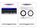
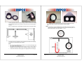
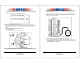
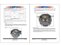
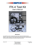
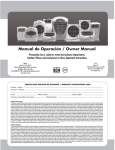
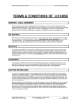
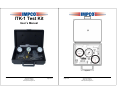
ITK-1 Test Kit
User’s Manual
Figure #1
PPI-109-REV.A
IMPCO Technologies Inc.
3030 South Susan St.
Santa Ana, CA 92704
www.impcotechnologies.com
December, 2007
Page 1 of 10
December, 2007
Page 2 of 10
IMPCO Technologies Inc.
3030 South Susan St.
Santa Ana, CA 92704
www.impcotechnologies.com
PPI-109-REV.A
Chapter I
ITK-1 Test Kit Contents
Chapter II
Tool Usage Instructions
The ITK-1 Test Kit contains all items listed in table #1. If your kit is missing any component, or has any
damaged items, please call your IMPCO distributor for instructions.
ITEM
1
2
3
4
5
6
7
8
9
10
11
(Not Shown)
DESCRIPTION
QTY USED
Bushing, Model J
Fitting, 1/8” NPT / 3/16” HS Nip Brass
Hose, 3/16” ID Vacuum, Bulk
Test Kit Gauge, 0-5 PSI
Test Kit Gauge, 0-10” WC
Test Kit Gauge, 200 PSI
Fitting, ¼ UNF, ¼ HS Vac Nip
Fitting, 1/8” NPT ¼” HS 90O El Nylon
Gauge, Secondary Lever Height
Case, Plastic
1
1
8 feet
1
1
1
1
1
1
1
IMPCO PART
NUMBER
B3-26
F4-4
H1-11
TG-005
TG-010
TG-0200
F4-2
F4-8
G2-2
C9-25849-003
ITK-1 User’s Manual
1
PPI-109
A. High Pressure Gauge (TG-0200):
This pressure gauge is used for input fuel pressure readings. Connectivity depends entirely upon
your application. Do not connect the gauge where the delivery pressure will exceed 200 PSI.
B. Differential Pressure Test Gauges (TG-005 & TG-010):
•
Both the TG-005 (0-5 PSI) and the TG-010 (0-10” WC) are differential pressure gauges. This
means they can be used to measure the difference in pressures between two separate areas or
they can be used to measure either positive pressure or negative pressure (vacuum).
Table #1
TG-005
•
TG-010
Before using either of the differential pressure test gauges, they should to be calibrated against a
manometer or a known calibrated gauge. To calibrate a gauge:
Remove the front cover by unscrewing it in a counter-clockwise direction. You may need to use
a pair of channel lock style pliers (be careful as the cover is made of plastic). DO NOT use any
clamping tool on the body of the gauge.
PPI-109-REV.A
IMPCO Technologies Inc.
3030 South Susan St.
Santa Ana, CA 92704
www.impcotechnologies.com
December, 2007
Page 3 of 10
December, 2007
Page 4 of 10
IMPCO Technologies Inc.
3030 South Susan St.
Santa Ana, CA 92704
www.impcotechnologies.com
PPI-109-REV.A
If utilizing a positive pressure to calibrate the gauge, make the connections as illustrated.
If using a negative pressure source (vacuum), connect the hose to the center nipple on
the gauge.
NOTE: The applied pressure should ideally be between 50-80% of the gauge capacity.
•
•
Replace the cover, pressurize and compare to known good gauge for accuracy.
Repeat steps as necessary until the gauge is properly calibrated.
NOTE:
• If a manometer or a known calibrated gauge is not available, make sure the gauge is
“zeroed” and the needle is not indicating a pressure or “pinned” when sitting idle. This
method usually results in an accuracy within +/- 1.5” w.c.
If the gauge needs to be calibrated, insert the provided Allen wrench into the adjusting
screw and turn to make adjustments as necessary.
NOTE:
•
The cover must be installed (with o-ring) when in use. Pressure will discharge from
front of gauge without cover in place.
•
The gauge must be calibrated in the same position in which it is used—a change in
orientation may cause the needle to travel, resulting in a change of measurement.
•
A bracket can be made to hold the gauges in the upright position (see next page).
A properly calibrated TG-010 Gauge
PPI-109-REV.A
IMPCO Technologies Inc.
3030 South Susan St.
Santa Ana, CA 92704
www.impcotechnologies.com
December, 2007
Page 5 of 10
December, 2007
Page 6 of 10
IMPCO Technologies Inc.
3030 South Susan St.
Santa Ana, CA 92704
www.impcotechnologies.com
PPI-109-REV.A
•
If the differential pressure between two chambers or compartments is required, such as a turbo
application, make the connections as illustrated. Verify that the expected pressure differential
does not exceed the limits of the gauges before connecting.
5. Sparingly apply LoctiteTM 567 or equivalent thread sealant on the threads of the pressure test
adapter and install it into the regulator primary test port (torque F4-4 to 10 ft-lb, finger tight the
F4-8 plus 1 ½ turns).
6. Connect one end of a section of 3/16” vacuum hose (H1-11) to the hose nipple on the pressure
test adapter and the other to the outside hose nipple on differential gauge TG-005 (see section
B in this chapter for gauge connections).
C. Primary Pressure Test Adapters (F4-4 & F4-8):
P/N F4-4 is a straight adapter for connections where there are no obstructions in front of the
regulator primary test port. P/N F4-8 is a 90O adapter for connections where some obstruction may
hinder the use of the straight adapter. To connect either adapter to the primary test port of a
regulator:
1. Shut off the fuel tank manual shut-off valve.
2. Start the engine and let it run until it dies from lack of fuel.
3. Turn off the ignition key.
4. Remove the Primary Test Port Plug from the regulator.
Cobra illustrated with F4-4. The F4-8 is similar
7. Open the fuel tank manual valve and test for leaks before starting the engine.
•
When reinstalling the test port plug, clean all traces of old sealant from the threads, apply a
minimal amount of LoctiteTM 567 or equivalent thread sealant on the plug threads and install
into the regulator (torque to 10 ft-lb).
•
Test for fuel leaks before starting the engine.
Cobra Regulator, showing the primary pressure test port. Other regulators have a similar port.
PPI-109-REV.A
IMPCO Technologies Inc.
3030 South Susan St.
Santa Ana, CA 92704
www.impcotechnologies.com
December, 2007
Page 7 of 10
December, 2007
Page 8 of 10
IMPCO Technologies Inc.
3030 South Susan St.
Santa Ana, CA 92704
www.impcotechnologies.com
PPI-109-REV.A
•
D. Secondary Lever Height Gauge (G2-2):
The secondary lever height gauge is actually two gauges in one. One side provides the secondary
lever heights for the Model E & Model L regulators and the other side has the mounting hole
templates for the Model J, L, EV & E regulators and the Model VFF lockoff.
Model L:
With the secondary chamber cover off, lay the gauge on the regulator body with the secondary
lever inside the slot labeled “L” as illustrated. The gauge should just contact the secondary
lever without being lifted from the body. Make any necessary adjustments by removing and
carefully bending the secondary lever.
NOTE:
Bending the lever in place may result in damage to the seat.
Secondary Lever Height Gauge (G2-2)
To use as a mounting-hole template:
The left hole (under the word “COMMON”) is common hole when using the gauge as a mounting
template. Locate the hole under the model number of the regulator or lockoff you are using for the
other hole.
To use as secondary lever height gauge:
•
Model E:
With the secondary chamber cover off, lay the gauge on the regulator body and slide the slot
labeled “E” over the secondary lever pin as illustrated. If the pin will not easily slide into the slot
or lifts the gauge up off of the body, remove and carefully bend the lever until it slides in without
force and does not lift the gauge.
Model “L” Regulator
NOTE:
Bending the lever in place may result in damage to the seat.
E.
Model “J” Bushing:
The Model “J” bushing is used in conjunction with either the F4-4 or F4-8 pressure test adapter for
performing a secondary pressure test on a Model “J” regulator/converter. To perform the test,
remove the ½” NPT plug from the unused vapor fuel outlet. Apply a small amount of LoctiteTM 567
or equivalent thread sealant on the bushing threads and install the bushing in the outlet. Then,
apply some of the sealant onto the F4-4 or F4-8 pressure adapter and install it into the bushing.
Connect the 3/16” vacuum hose to the adapter and the other end of the hose to the proper pressure
gauge nipple (depending on fuel type).
Model “E” Regulator
PPI-109-REV.A
IMPCO Technologies Inc.
3030 South Susan St.
Santa Ana, CA 92704
www.impcotechnologies.com
December, 2007
Page 9 of 10
December, 2007
Page 10 of 10
IMPCO Technologies Inc.
3030 South Susan St.
Santa Ana, CA 92704
www.impcotechnologies.com
PPI-109-REV.A