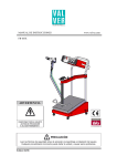
1
Rev-B
TABLE OF CONTENTS
SAFETY (READ FIRST) ................................................................................................................................1
INTRODUCTION ...........................................................................................................................................3
A. Important Vehicle Owner Advisories................................................................................................3
B. SEQUENT P&D Installation Kit Contents ........................................................................................3
C. Required Tools & Equipment ...........................................................................................................5
D. Torque Specifications ......................................................................................................................5
E. Installation Note (corrosion protection) ............................................................................................5
INSPECT FOR CORRECT VEHICLE INFORMATION & THE OPERATIONAL INTEGRITY OF THE
ENGINE .........................................................................................................................................................6
A. Preliminary Inspection .....................................................................................................................6
B. Scan Tool Inspection .......................................................................................................................6
C. High Mileage Vehicle Inspection (75k+) ..........................................................................................7
SEQUENT P&D INSTALLATION..................................................................................................................8
A. Pre-Installation Bench Assembly .....................................................................................................8
B. Intake Manifold, Ignition Coil Pack and Air Filter Housing Removal ..............................................11
C. Intake Manifold Modifications ........................................................................................................11
D. Zenith Regulator and Coolant Hose Installation ............................................................................13
E. Lockoff and High Pressure Tubing Installation ..............................................................................14
F. Fuel Rail Installation ......................................................................................................................15
G. CNG Low Pressure Hose Connections .........................................................................................16
H. Sequent / OEM ECM Electrical Connections .................................................................................17
•
Proper Wire Splicing ...............................................................................................................17
I. Sequent ECM, Relay & Fuse Locations ........................................................................................20
J. Battery Connections ......................................................................................................................20
K. Re-install the Ignition Coil Pack and Upper Intake Manifold ..........................................................21
L. Sequent MAP Sensor Installation ..................................................................................................21
M. OBD-II Connections and Changeover Switch / Buzzer Installation ...............................................22
N. Sequent Component Electrical Connections .................................................................................23
O. Final Connections ..........................................................................................................................23
P. Fuel Level Calibration ....................................................................................................................23
Q. Initial Engine Start..........................................................................................................................24
R. Sequent “Delta-P” Pressure Adjustment ........................................................................................24
S. Warranty Card, Labels and Owner’s Guide ...................................................................................25
T. Maintenance ..................................................................................................................................27
SAFETY
READ BEFORE PERFORMING ANY INSTALLATION, SERVICE,
MAINTANENCE OR REPAIR ON THE FUEL SYSTEM
There are safety regulations and standards that must be followed when installing or servicing
gaseous fuel equipment. It is highly recommended you obtain and read the following National
Fire Protection Association (NFPA) guidelines:
SERVICE TECHNICIANS AND USERS:
CAREFULLY READ AND ABIDE BY THE PROVISIONS SET FORTH IN NATIONAL FIRE
PROTECTION ASSOCIATION PAMPHLET #37 FOR STATIONARY ENGINES, #52 FOR CNG
VEHICULAR FUEL SYSTEMS OR #58 FOR LPG SYSTEMS.
INSTALLERS:
LPG INSTALLATIONS IN THE UNITED STATES MUST BE DONE IN ACCORDANCE WITH
FEDERAL STATE OR LOCAL LAW, WHICHEVER IS APPLICABLE AND NATIONAL FIRE
PROTECTION ASSOCIATION PAMPHLET #58, STANDARD FOR STORAGE AND HANDLING OF
LIQUIFIED PETROLEUM GASES TO THE EXTENT THESE STANDARDS ARE NOT IN VIOLATON
WITH FEDERAL, STATE OR LOCAL LAW.
IN CANADA REFER TO CAN/CGA PROPANE INSTALLATION CODES.
CNG INSTALLATIONS IN THE UNITED STATES MUST BE DONE IN ACCORDANCE WITH
FEDERAL STATE OR LOCAL LAW AND NATIONAL FIRE PROTECTION ASSOCIATION
PAMPHLET #52, COMPRESSED NATURAL GAS (CNG) VEHICULAR FUEL SYSTEMS TO THE
EXTENT THESE STANDARDS ARE NOT IN VIOLATION WITH FEDERAL, STATE OR LOCAL
LAW.
IN CANADA REFER TO CAN/CGA CNG INSTALLATION CODES.
LPG AND/OR NATURAL GAS INSTALLATIONS ON STATIONARY ENGINES MUST RE DONE IN
ACCORDANCE WITH FEDERAL, STATE OR LOCAL LAW AND NATIONAL FIRE PROTECTION
ASSOCIATION PAMPHLET #37, STATIONARY COMBUSTION ENGINES AND GAS TURBINE
ENGINES, TO THE EXTENT THESE STANDARDS ARE NOT IN VIOLATION WITH
FEDERAL,STATE OR LOCAL LAW. FAILURE TO ABIDE BY THE ABOVE WILL VOID ANY IMPCO
WARRANTY ON THE PRODUCTS AND MAY CAUSE SERIUS INJURY OR PROPERTY DAMAGE.
DUE TO THE INHERENT DANGER OF GASEOUS FUELS, THE IMPCO PRODUCTS SHOULD NOT
BE INSTALLED OR USED BY PERSONS NOT KNOWLABLE OF THE HAZARDS ASSOCIATED
WITH THE USE OF GASEOUS FUELS.
To order these documents, call the NFPA @ 800 344-3555 or go to www.nfpa.org.
There are state standards and regulations enforced by the state fire marshal in most states. In
Texas, the Texas State Railroad Commission sets standards.
There may be other local standards set by counties, cities and municipalities. Be sure to
consult all regulatory agencies to assure adherence to all standards in enforcement.
Safety in the workplace is everyone’s responsibility. Regardless of the type work you do, it is
very important that you pay attention to what you are doing for your safety and the safety of
those around you.
©2009 IMPCO Technologies, Inc.
-1-
2009 3.5/3.9L Impala CNG
The following points are things to keep in mind when working on internal combustion engines
and gaseous fuel systems:
9 Before working on any fuel system, study the NFPA standard for the fuel in use.
9 Before working on any fuel system, read and understand all manufacturers’ recommended
procedures.
9 Before working on any fuel system, make sure you have local code approved safety
goggles, face shields, gloves and clothing.
9 Before working on any fuel system, make sure there is adequate ventilation.
9 Before working on any fuel system, turn OFF the fuel system supply valve and slowly bleed
the fuel from all lines before working on the fuel system or engine.
©2009 IMPCO Technologies, Inc.
-2-
2009 3.5/3.9L Impala CNG
INTRODUCTION
A. Important Vehicle Owner Advisories:
•
At the time of this writing, the Sequent P&D system has not been certified by the California Air
Resources Board (CARB). If the vehicle is moved to California, it may not be registered
without returning the vehicle to as-close-as-possible to original condition. Please inform the
customer that emissions standards vary state to state and to check with the emissions
enforcement agency or DMV prior to moving the vehicle into another state. IMPCO is
pursuing a (CARB) certification. Contact IMPCO for certification status and updates.
•
The EPA certification on the 2009 GM 3.5/3.9L Impala covers vehicles with the E85 fuel
option. It is important that the vehicle be run on gasoline with a maximum of 10%
alcohol content with the Plug & Drive system. Operation on E85 fuel may cause rough
engine running and possible check engine light illumination during or shortly after the
changeover to CNG operation. Please advise your customers before installing the
system.
B. SEQUENT P&D 2009 3.5/3.9L Impala Installation Kit Contents:
Remove all kit package contents and verify all parts are included and undamaged. Do not attempt to
repair any damaged parts. Contact IMPCO Technologies for replacement of damaged or missing
parts.
Part Number SQ‐50846‐02‐0010 E010M9006 VI050013 DE802060 FE077246 09SQ99020002G H1‐51561‐003‐0900 VI050028 21RG99020001 06LB00001988 DE524010 09SQ00990002 H1‐51561‐001‐0330 16PM00010020 DE802055 21RG03010006 18CE00010070 06LB50010068 H1‐51561‐002‐0900 25TA01010005 H1‐51561‐001‐0700 09SQ99030078M 09SQ99030559M B4‐51389‐001 B4‐51390‐001 N1‐30876‐M06 Description Kit, Sequent P&D, Impala 3.5/3.9L CNG Certified REGULATOR, ZENITH 1/4NPT CLAMP, NO.95 FOR 5X10MM HOSE SENSOR ASSY, MAP FITTING, M6 FUEL END NOZZLE INJECTOR,BRC LPG MAX FLOW,ORNG HOSE, BRC CUT, 12MM X 900MM CLAMP, NO.170 FOR 12X19MM HOSE FITTING, 6MM HOSE VACUUM "Y" SWITCH, FUEL SELECTOR HARNESS, P&D 6 CYL, W/PTS CNG FITTING, VAPOR FUEL Y, 10X12MM HOSE, BRC CUT, 5MM X 330MM LOCKOFF, HIGH PRESSURE 1/4NPT SENSOR, 4 BAR PRESSURE / TEMP FITTING, 6MM BARBED MANOMETER, 0‐250 BAR, 0‐90 OHM HARNESS, PRESSURE SENSOR HOSE, BRC CUT, 8MM X 900MM FITTING, NYLON "T" 16X16X8MM HOSE, BRC CUT, 5MM X 700MM RAIL, BRC FUEL INJECTOR RAIL, BRC INJECTOR W/PTS PORT BRACKET, RAIL 1 '08 IMPALA CNG BRACKET, RAIL 2 '08 IMPALA CNG NUT, HEX FL SR M6X1.0 ©2009 IMPCO Technologies, Inc.
-3-
Quantity NA 1 20 1 6 6 1 8 1 1 1 1 6 1 1 1 1 1 1 2 1 1 1 1 1 4 2009 3.5/3.9L Impala CNG
Part Number S1‐30871‐02‐0616 S1‐30871‐02‐0612 L3‐50820‐016 S1‐30295‐0650 S1‐30871‐02‐0812 C2‐14106‐004 C2‐14106‐006 B4‐51391‐001 PPI‐A‐004 PPI‐A‐005 H5‐15342‐1 T4‐50880‐001 T4‐50879‐001 92920000 G3‐51280‐001 S3‐51446‐002 H1‐50912‐001 FE077245‐3 FE077244 DE815186 L3‐51732‐001 W3‐14211‐000 L3‐51853‐001 L3‐51854‐001 L3‐51857‐001 Description Screw, Hex Flange, M6 x 16MM SCREW, HEX FL M6X12MM LABEL, EMISSION GM'09 3.9L CNG SCREW, HEX SOCKET CAP SCREW,HEX FLANGE‐M8X1.25X12 Clamp, Hose 5/16"Od 7/8" Gear Clamp, Hose 1/2 To 1 1/8 Sae10 BRACKET, REG '08 IMPALA CNG MANUAL, OWNERS SEQUENT P&D CNG SEQUENT WARRANTY REGISTRATION TUBING, HEATSHRINK 3/16" BULK TERM.,EYE 1/4" STUD 12‐10 GA TERMINAL, WIRE SPLICE 22‐16 GA Washer, Flat M6 DIN 433 GROMMET, RUBBER 1/4"IDX1"OD SPACER, ECM, BRC SEQUENT HOSE, FORMED 1/2" ID FUEL FITTING, M8 FUEL HOSE BARBED NUT, M8X1 ES. 10 TURN FITTING ECM, P&D '09 IMPALA CNG CERT LABEL, MAX W.P. FOR AUTO HOSE CONDUIT, ROUND CONVOLUTED LABEL, OWNER’S GUIDE ADDENDUM, E85, LPG LABEL, OWNER’S GUIDE, E85 NOTICE, LPG LABEL, FUEL DOOR E85 NOTICE ©2009 IMPCO Technologies, Inc.
-4-
Quantity 2 4 1 2 3 4 4 1 1 1 4 ft 2 35 2 1 2 2 12 12 1 10 7 ft 2 2 2 2009 3.5/3.9L Impala CNG
C. Required Tools, Equipment & Supplies:
•
Sequent Installer’s Tool Kit (part # 90AV99004048)
•
Software Installation Kit (part # 90AV99002055)
•
SAE and metric mechanic’s hand tools
•
Electric or cordless drill and assorted drill bits
•
Large hose clamp pliers
•
Heat gun
•
Soldering iron
•
Solder (60/40 electronic rosin core – 0.7 to 1mm diameter works best)
•
DVOM and assorted test leads
•
Wire/Terminal crimper(s) capable of handling 10-12 gauge (5.5mm2), non-insulated barrel
terminals and 18-16 gauge (2.0mm2) “U” style splices
•
Wire stripper
•
Electrical tape
•
PC or laptop with Sequent P&D software installed
•
Leakdown tester
•
Standard mechanic’s diagnostic tools
•
OBD-II compliant scan tool (CAN enabled)
•
OEM Upper Intake Manifold Gasket Set
•
OEM Factory Service Manual
•
NFPA approved CNG high-pressure tubing and fittings as necessary
•
OEM touchup paint to match vehicle
D. Torque Specifications:
•
•
•
•
•
•
•
•
•
•
E.
CNG high pressure filter mounting (banjo) bolt ........................... 15-22 ft-lbs (20-30 Nm)
CNG high pressure filter blocking screw ..................................... 37-52 ft-lbs (50-70 Nm)
CNG manometer......................................................................... 15-30 ft-lbs (20-40 Nm)
CNG pressure / temperature sensor ..................................... 20.5-23.5 ft-lbs (28-32 Nm)
Regulator Temperature Sensor ............................................................. 89 in-lb (10 Nm)
MAP sensor mounting nut .................................................... 20.5-23.5 ft-lbs (28-32 Nm)
Fuel nozzles...................................................................................... Hand tight + ¼ turn
BRC Injector mounting nuts ................................................................... 71 in-lbs (8 Nm)
Fuel hose & manifold vacuum hose adapter nuts (8mm) ....................... 62 in-lbs (7 Nm)
Zenith regulator mounting bolts (8mm) .............................................................. 15 ft-lbs (20 Nm)
Installation Notes:
•
Anytime the OEM painted surface is broken by drilling, component removal, etc, the exposed
metal surfaces must be protected from corrosion. This is especially important in areas where
salt is used on the roads during the winter months. GM recommends their Super Lube with
PTFE (part #12371287, GM bulletin # 03-00-89-008D). Follow the instructions in the bulletin
to ensure a positive outcome.
•
DO NOT use Teflon tape on any fittings. Teflon tape may get into the regulator primary and
secondary seats and the fuel injector seats causing fuel pressure problems. Any warranty
returned item found contaminated with Teflon tape will be returned.
©2009 IMPCO Technologies, Inc.
-5-
2009 3.5/3.9L Impala CNG
INSPECT FOR CORRECT VEHICLE INFORMATION AND THE
OPERATIONAL INTEGRITY OF THE ENGINE
Installing an alternative fuel system into a vehicle with an engine or ignition system that is in poor
condition will produce less than desirable results and may lead to exhaust emissions beyond
acceptable levels. It is strongly advised that all of the following inspections be done BEFORE installing
the Sequent P&D system.
A. Preliminary Inspection:
The preliminary inspection should consist of a visual inspection of the following items:
•
Emissions Label for correct Model Year, Engine Group, Evaporative Emissions Family and
Engine Type:
o Model Year: 2009 ONLY
o Engine Group: 9GMXV03.9052 ONLY
o Evaporative Emissions Family: 9GMXR0133810 ONLY
Correct MY, Engine Group & Evaporative Emissions Family.
NOTE: If the Emissions label identification information does not match exactly, you
CANNOT install the system in the vehicle. Installation in a non-certified vehicle may be
punishable by a fine and/or imprisonment.
•
•
•
•
•
•
•
Air filter and intake plumbing condition.
Engine gaskets and seals for leaks.
Exhaust system condition.
Cooling system for leaks.
Under-hood wiring and hose condition.
Inspect the secondary ignition wires, ignition coils and suppressor caps for any signs of
damage or wear.
Repair or replace any faulty items.
B. Scan Tool Inspection:
Connect an OBD-II compliant scan tool to the vehicle DLC connector and check the following:
•
Active or Historic fault codes (follow the OEM’s diagnostic recommendations for any codes
found and make necessary repairs).
•
OBD monitors for completion and passed tests.
o If all applicable monitors have not completed, drive the vehicle until they have completed
and passed.
o If any monitors have failed a test, follow the OEM’s diagnostic recommendations and
make any necessary repairs.
©2009 IMPCO Technologies, Inc.
-6-
2009 3.5/3.9L Impala CNG
C. High Mileage Vehicle Inspection (75k+) or scan tool not available:
High mileage vehicles require further inspection. The following items require physical inspection:
•
Start the engine and inspect the exhaust for signs of excessive smoke.
•
Remove the engine dip stick and inspect the oil condition. Change oil and filter if necessary.
•
Remove and inspect spark plugs. Replace the plugs if any are found to be worn, show signs
of gas fouling or oil contamination.
•
Perform a leak-down test.
MAKE ANY NECESSARY REPAIRS BEFORE INSTALLING THE SEQUENT SYSTEM.
©2009 IMPCO Technologies, Inc.
-7-
2009 3.5/3.9L Impala CNG
SEQUENT P&D INSTALLATION
A. Pre-Installation Bench Assembly:
1) Locate the six fuel injectors and both fuel
rails. The injectors will be installed into
the rails as illustrated.
2) Install three Sequent injectors into each
of the fuel rails and torque the injector
nuts to 71 in-lb (8 Nm). Install the Fuel
Temperature / Pressure Sensor into the
longer of the two rails and torque the
sensor to 20.5-23.5 ft-lbs (28-32 Nm).
NOTE: Numbering the fuel rail as
illustrated will help when connecting the
harness to the injectors.
3) Install the Regulator Temperature Sensor
onto the Zenith Regulator and torque it to
89 in-lb (10 Nm).
©2009 IMPCO Technologies, Inc.
-8-
2009 3.5/3.9L Impala CNG
4) Insert the aluminum sealing washer into
the CNG manometer receiver on the
high-pressure filter and install the
manometer. Tighten the manometer so it
is in the approximate position keeping the
torque between 15-30 ft-lbs (20-40 Nm).
5) Install the High Pressure Filter onto the
regulator. Rotate the filter to the position
shown and torque the banjo bolt to 15-22
ft-lbs (20-30 Nm). DO NOT over-tighten!
6) Lightly apply Loxeal to the two regulator
bolt threads and install the regulator onto
the bracket.
©2009 IMPCO Technologies, Inc.
-9-
2009 3.5/3.9L Impala CNG
7) Assemble the fuel hoses by inserting the
barbed hose fittings through the 8mm
special nuts and into the ends of the fuel
hoses. Install two clamps over the hoses
centering them over the barbed fittings
and clamping them with the hose clamp
pliers.
8) Thread the fuel nozzles into one end of
the fuel hoses and torque them to 62 inlbs (7 Nm).
NOTE: Hose illustrated not actual length.
9) After all fuel hoses have been cut to
length and assembled, wrap one of the
maximum fuel working pressure labels
around EACH hose.
10) Wrap the label around the hose “Towards
one end of the hose” (as illustrated). DO
NOT affix the label along a bend in the
hose as it may cause a kink in the hose
restricting fuel flow.
11) One of these labels must be affixed to
every fuel hose between the regulator
outlet and the intake manifold to
comply with government regulations.
Sample Illustration
©2009 IMPCO Technologies, Inc.
-10-
2009 3.5/3.9L Impala CNG
B. Intake Manifold, Ignition Coil Pack and Air Filter Housing Removal:
Prior to any disassembly, clean the engine and engine compartment (with engine degreaser where
necessary). Disconnect the negative battery cable followed by the positive battery cable and remove
the battery from the vehicle. Following the manufacturer’s service manual instructions, remove the
upper intake manifold, then the ignition coil pack. Remove the air filter housing to expose the ECM.
C. Intake Manifold Modifications:
1) Using a straight edge, draw two lines along
the intake manifold keeping the straight
edge just inboard of the runner numbers.
Using a center punch, make a small dimple
where the lines intersect in the photo
(arrows).
NOTE: Lower intake manifold has been
removed from the engine for clarification. DO
NOT remove the lower intake manifold from the
engine.
2) Before drilling & tapping the runners, cover
all of the intake ports and OEM injector
holes except for those on the runner you
will be drilling & tapping. Using a rubber
tipped blow gun, blow air into the runner
being drilled and tapped so all metal chips
will be carried out of the runner through the
intake runner opening. Also, incorporating
a wet/dry vacuum on the intake runner
opening will help evacuate metal chips from
the runner.
IMPORTANT: Make sure the intake valve
for the cylinder you are working on is
completely closed. If not, rotate the engine by
hand until it is.
BE SURE to wear goggles and a face mask
to protect your eyes from flying particles.
3) While blowing air through one of the
runners, and using one of the 5mm drills in
the Sequent Installer’s Tool Kit, drill through
the top intake manifold runner wall keeping
the drill perpendicular to the runner face.
DO NOT drill into the bottom wall of the
runner.
©2009 IMPCO Technologies, Inc.
-11-
2009 3.5/3.9L Impala CNG
4) Attach the long tap handle to the
combination 6x1mm tap & drill. Apply a
light coat of tapping oil to the tap threads
and tap the nozzle hole keeping the tap
perpendicular to the runner face. Repeat
steps 3 – 5 for the remaining five intake
runners. When finished, clean all traces of
metal chips from the intake runners.
5) Apply a light coat of Loxeal to each of the
fuel hose nozzle threads.
6) Thread the fuel hose/nozzle assemblies
into the tapped holes. Using the nozzle
crow’s foot tool (or 10mm wrench) tighten
each fuel hose/nozzle assembly
approximately ¼ turn past hand-tight.
©2009 IMPCO Technologies, Inc.
-12-
2009 3.5/3.9L Impala CNG
7) Apply some clean engine oil to the OEM
injector o-rings and install the OEM fuel
injector rails torqueing the bolts to OEM
specifications.
Intake manifold with OEM fuel injector rails
installed and Sequent fuel hoses routed
correctly.
8) Drill and tap the upper intake manifold for
the brass vacuum port adapter using the
5mm drill and the 6mm tap. Clean all
traces of metal chips from the manifold.
Apply a light coat of Loxeal to the adapter
threads before installing.
Set the upper manifold aside in a clean
area protected from dirt and debris.
Cover the lower manifold to keep dirt and
debris from entering the intake runners.
D. Zenith Regulator and Coolant Hose Installation:
1) The Zenith Regulator will be installed in the
center of the bulkhead utilizing three
existing studs.
©2009 IMPCO Technologies, Inc.
-13-
2009 3.5/3.9L Impala CNG
2) Begin modifying the heater hoses by
pinching them with four hose pliers to make
room for the two plastic Tees.
3) Cut the heater hoses between the clamps,
install four hose clamps onto the hoses and
install the two plastic Tees.
4) Temporarily install the Regulator and cut
two lengths of the Regulator Coolant Hose
to fit between the two Tees and the
Regulator coolant hose nipples.
5) Slide hose clamps onto the two hoses and
install them onto the Tees.
6) Tighten the six clamps on the Tees and
remove the hose pliers.
Heater hoses with Tees and Regulator Coolant
Hoses installed
7) Slide two more hose clamps onto the
Regulator Coolant Hoses, install the hoses
onto the Regulator and tighten the clamps.
8) Install the Regulator onto the engine
compartment rear bulkhead studs.
E.
Lockoff and High Pressure Tubing Installation:
1) Locate the Lockoff bracket and mark it for
modification as illustrated. Cut off the end
of the bracket, drill two ¼” diameter holes
as indicated and bend the bracket 90o
where indicated. Round off any sharp
corners with a file or grinder.
©2009 IMPCO Technologies, Inc.
-14-
2009 3.5/3.9L Impala CNG
2) The bracket will be mounted on the
driver’s side shock tower close to the top.
Bend the bracket as illustrated to
approximate the mounting surface of the
shock tower.
3) Install the Lockoff onto the bracket as
illustrated. Using the bracket as a
template, drill two ¼” diameter holes in
the shock tower. Mount the Lockoff and
bracket to the shock tower.
IMPORTANT: If the vehicle has ABS, be
sure to allow for clearance between the
Lockoff and the ABS Unit / lines.
4) Using code approved fuel line and fittings,
fabricate a fuel line to connect between
the lockoff and the regulator.
F.
Fuel Rail Installation:
1) Wrap each of the six fuel hoses with
corrugated conduit (make sure the max
wp labels are installed first).
2) Mount the 1-3 fuel rail onto its bracket.
Attach fuel hoses 1-3 to the appropriate
injector routing the hoses as indicated in
the photo.
3) Tie-wrap #2 & 3 hoses to the OEM fuel
rails where indicated in the photo.
1-3 Fuel Rail Bracket
©2009 IMPCO Technologies, Inc.
-15-
2009 3.5/3.9L Impala CNG
4) Mount the 4-6 fuel rail onto its bracket.
Attach fuel hoses 4-6 to the appropriate
injector routing the hoses as indicated in
the photo. Tie wrap #4 & 5 hoses to the
OEM fuel rails where indicated in the
photo.
4-6 Fuel Rail Bracket
G. CNG Low Pressure Hose Connections:
1) Locate the two preformed low pressure
fuel hoses, the length of bulk fuel hose and
the fuel splitter “Y”.
2) Install the short preformed hose onto the
Regulator fuel nipple, slide two fuel hose
clamps onto the hose and install the other
end onto the single “Y” inlet nipple.
5) Slide two fuel hose clamps onto the other
preformed hose and install the end with the
sharp bend onto one of the “Y” outlet
nipples and the other onto the 4-6 fuel rail
inlet nipple.
6) Position the two fuel rails approximately in
their installed locations and cut the bulk
fuel hose to length to fit between the other
“Y” outlet nipple and the 1-3 fuel rail.
Install two fuel hose clamps onto the hose
and install it.
7) Secure all fuel hose clamps with the hose
clamp pliers in the Sequent Installer’s Tool
Kit.
8) Re-install the ignition coil pack.
Low Pressure Fuel Hoses Installed
©2009 IMPCO Technologies, Inc.
-16-
2009 3.5/3.9L Impala CNG
H. Sequent / OEM Electrical Connections:
Proper Wire Splicing
Terminal Crimping Types:
There are two types of terminals used in the installation of the Sequent P&D wiring harness. To
ensure a good crimp, use the appropriate style crimping tool (including correct gauge) as illustrated
below.
NOTE: Not all crimping tools are made exactly the same. Experiment with different tools to
achieve the best crimps possible before working on the vehicle’s wiring harness.
The first is the “U” style splice crimp used to splice the Sequent P&D harness circuits to the OEM
harness circuits.
“U” Style Crimping Tool
“U” Style Crimp (Before & After Crimping)
The second is the “Barrel” style, non-insulated lug terminal used to connect the Sequent P&D
harness to the battery post terminals.
“Barrel” Style Non-Insulated Crimping Tool
“Barrel” Style Crimp (Before & After Crimping)
IMPORTANT NOTE: After crimping either style terminal, be sure to solder the connection as illustrated
on the next page before shrink wrapping.
©2009 IMPCO Technologies, Inc.
-17-
2009 3.5/3.9L Impala CNG
Soldering Crimps & Terminals:
Solder all terminals after crimping as illustrated using an electronic grade, rosin core solder (0.7 to
1.0mm diameter works best). Make sure all wires in the terminal receive adequate solder to ensure
a permanent connection.
“Barrel” Style Lug Terminals
“U” Style Splice Crimps
Heat the terminal and apply the solder from the
lug side of the crimp to minimize “wicking” solder
up the wires, which may lead to wire breakage.
Securing the wires to the battery cables will help
minimize this risk.
Heat the terminal and apply the solder in the
center of the crimp fold, allowing it to “wick” into
the joint. Do not worry if some of the solder wicks
into the wires as they will be secured by the wiring
loom.
Shrink Wrapping Connections:
Shrink wrap all splices and the positive battery lug. Cut the adhesive lined shrink tubing into 1 to 1
½” (25-38mm) pieces. Use a heat gun with a U-shaped nozzle to heat the shrink tubing uniformly
as illustrated.
IMPORTANT!
Familiarize yourself with ALL schematics and electrical diagrams BEFORE splicing wires.
Some of the modules and Sequent ECU share the same electrical connections (splices).
©2009 IMPCO Technologies, Inc.
-18-
2009 3.5/3.9L Impala CNG
1) Disconnect both connectors from the OEM
ECM. Layout the Sequent wiring harness
with all pigtails approximately where they
will be installed.
2) Carefully remove the wiring cover from the
back of the OEM ECM connectors X1 & X2.
3) Remove the harness tape and conduit to
expose the ECM connector wiring.
OEM ECM harness with modifications
completed and ready for retaping.
4) Locate both injector pigtails on the Sequent
P&D harness (labeled: Inj 1-2-3-4 BENZ
and Inj 5-6-7-8 BENZ). Cut the connectors
off of both pigtails.
5) Cut the adhesive-lined shrink-wrap into 1 to
1 ¼” strips. Install one of the strips over the
first wire to be reworked.
6) Steps 6 through 9 should be done on the
wires one-at-a-time. Referring to the 2009
3.5L Impala P&D Installer’s Wiring
Diagram, cut each wire at the ECM
indicated on the diagram. Strip the ends of
the wires in preparation for crimping and
soldering.
Important: Make sure to cut the wires so
there is adequate space between the splice
and the ECM connector to allow for repacking
the wires into the harness conduit.
7) Position the wire ends in one of the “U”
shaped crimps and securely crimp the wires
together (parallel splice illustrated).
8) Solder the connection.
9) Apply the shrink-wrap to the splice.
10) Repeat until all circuits have been
reworked.
NOTE: The OBD-II connections cannot be
made until the interior harness pigtail has been
installed.
©2009 IMPCO Technologies, Inc.
-19-
2009 3.5/3.9L Impala CNG
I.
Sequent ECM, Relay & Fuse Locations:
1) Install the Sequent ECM (with spacers),
relay and fuses where indicated.
J.
Battery Connections:
Crimp and solder the terminals onto the red and black battery wires.
NOTES:
•
The B+ connection can be made directly to the battery or fuse box. DO NOT connect to any
circuit directly connected to the alternator/generator.
•
The B– connection can be made directly to the battery or engine/chassis ground. DO NOT
connect to ground near the alternator/generator due to electrical noise.
©2009 IMPCO Technologies, Inc.
-20-
2009 3.5/3.9L Impala CNG
K. Re-install the Ignition Coil Pack and the Upper Intake Manifold.
1) Following the OEM installation procedures,
re-install the ignition coil pack and (using
new gaskets) the upper intake manifold
with the Sequent injector rail brackets.
Manifolds removed from engine for clarification
purposes only.
L.
Sequent MAP Sensor Installation:
2) Fabricate the MAP Sensor bracket as
illustrated. Mount the MAP sensor in the
bracket torqueing the nut to 20.5-23.5 ftlbs (28-32 Nm).
MAP Sensor Bracket
3) Cut the MAP sensor vacuum hose to
match the illustration.
4) Remove the right upper Throttle Body
mounting bolt and secure the assembly to
the Throttle Body.
5) Connect the short hose to the vacuum
nipple on the upper intake manifold and
the long hose to the vacuum nipple on the
regulator.
©2009 IMPCO Technologies, Inc.
-21-
2009 3.5/3.9L Impala CNG
M. OBD-II Connections and Changeover Switch / Buzzer Installation:
1) Remove the grommet on the passenger
side of the bulkhead. Split the grommet
with a razor blade just enough to push the
Changeover Switch and OBD-II pigtails
through. Push the changeover switch
connectors through the hole, re-install the
grommet and seal it with a little black RTV
Sealant.
2) Make the OBD-II connections illustrated in
the 2009 3.5L Impala P&D Installer’s Wiring
Diagram.
3) The Changeover Switch can be installed in
either a 9/16” diameter hole or a 7/8”
diameter hole. The 7/8” hole is preferable if
the location surface is textured and less
than 3/32” thick. If the 9/16” hole is to be
used, attach the double-sided tape onto the
back of the switch. If the 7/8” hole is to be
used, remove the outer bezel from the
switch.
4) The Changeover Switch installation location
is a somewhat a matter of customer
preference. However, make sure the
Changeover Switch pigtail is long enough
for the customer’s preference. If not, make
suggestions for alternative locations.
5) The Buzzer is installed by installing the
double-sided tape to the back of the buzzer
and sticking to a clean smooth surface on
the back of the dash panel.
©2009 IMPCO Technologies, Inc.
-22-
2009 3.5/3.9L Impala CNG
N. Sequent Component Electrical Connections:
1) Connect the Sequent injector connectors.
Match the number on the injector wiring to
the CNG injector as illustrated.
Failure to follow this order will result in a rough
fuel change over and reduced performance on
CNG. Refer to the 2009 3.5L Impala P&D
Installer’s Wiring Diagram for additional
information.
2) Connect the fuel temperature / pressure
sensor.
3) Connect the regulator temperature sensor.
4) Connect lockoff.
5) Connect the Sequent ECM.
O. Final Connections:
1) Connect the high pressure CNG line to the
lockoff. Leak test the entire Sequent and
OEM fuel systems with applicable code
approved equipment before starting the
engine.
2) Reconnect all OEM components except for
the engine cover.
3) Reinstall the battery. If the installation
requires the Sequent B+ and B–
connections be made at the battery,
connect them now.
P.
Fuel Level Calibration:
1) Perform the fuel level calibration as
described in the Sequent P&D Display
Software User Manual.
©2009 IMPCO Technologies, Inc.
-23-
2009 3.5/3.9L Impala CNG
Q. Initial Engine Start:
1) After making all fuel system leaks and
installation inspections:
• Switch the changeover switch to Gasoline
operation (red FOIL).
• Connect an OBD-II scan tool to the OEM
DLC connector.
• Connect the Sequent DLC cable to the
vehicle and the laptop.
• Open the Sequent P&D software and start
the engine.
• With the OBD-II scan tool, verify there are
no pending or hard codes. If any codes
appear, diagnose the cause and repair
before continuing.
2) Let the engine warm up to operating
temperature, then depress the changeover
switch for gaseous operation position.
When the system begins changing over to
CNG operation the engine should continue
running without hesitation or stumbling. If
the engine begins running rough during the
changeover cycle, then 2 or more of the
injector connectors are misplaced. Perform
the Injector Changeover Test [Diagnostics
section of the Sequent P&D Display
Software User Manual (Cert)].
R. Sequent “Delta-P” Pressure Adjustment:
1. With the engine idling, running on CNG and
at operating temperature, open the display
software and select the “Delta P” pressure
for graphing (see the Diagnostics section in
the Sequent P&D Display Software User
Manual for graphing instructions). The
“Delta P” pressure should be averaging at
approximately 2000 mbar. If it is not, make
adjustments with a 4 mm allen wrench at
the regulator.
©2009 IMPCO Technologies, Inc.
-24-
2009 3.5/3.9L Impala CNG
S.
Warranty Card, Emissions Label & Owner’s Guide:
1) Warranty registration is available on
IMPCO Technologies’ Website:
http//www.impco.ws/sequent-tools.asp
(requires login).
If Internet registration is not possible, fill
out the warranty card completely and
drop it in the mail or fax it to:
714 656-1414
2) Fill out the Emissions Label completely
and attach it where illustrated.
©2009 IMPCO Technologies, Inc.
-25-
2009 3.5/3.9L Impala CNG
3) Install the Fuel Door E85 Notice label on
the inside of the fuel door.
4) Put the Sequent P&D Owner’s Guide in
the a prominent location on the dash or
center console where the customer can
easily locate it. It is strongly
recommended to go over some of the
highlights of the Owner’s Guide with the
customer.
©2009 IMPCO Technologies, Inc.
-26-
2009 3.5/3.9L Impala CNG
T.
Maintenance:
Maintenance consists of:
• Periodic visual inspection of all vacuum lines and fittings.
• Periodic visual inspection of all fuel lines and fittings.
• Periodically check entire intake system for vacuum leaks.
• Periodically check condition of all wiring.
• Periodic CNG lockoff fuel filter replacement.
• “Delta-P” fuel pressure manual inspection / adjustment.
Except for the “Delta-P” pressure check, all other maintenance items are in the IMPCO Owner’s Guide
Supplement. Consult the guide for maintenance schedules.
1) The Lockoff fuel filter replacement
requires the following parts:
Part #
02BM03990001
Description
Kit, Filter
Qty
1
PPI-A-021
Rev-B
August 09
Copyright © 2009 IMPCO Technologies, Inc. All rights reserved. Reproduction by any means, electronic or mechanical, including
photocopying, recording, or by any information storage and retrieval system or translation in whole or part is not permitted without written
authorization from IMPCO Technologies, Inc.
Created and published by IMPCO Automotive Technical Publications
©2009 IMPCO Technologies, Inc.
-27-
2009 3.5/3.9L Impala CNG
2009 3.5/3.9L Chevy Impala Sequent P&D
Installer’s Wiring Diagram
Rev-B
Underhood Fuse Box
Connector X1
Pnk
L- # 666666 (Org)
Fuel Supply Hoses
L- # 4444 (Org)
L- # 22 (Org)
Diagnostic
Connecor
To OEM
Injectors
Engine Firing Order:
1-2-3-4-5-6
Fuel Temp
& Press
Sensor
Yel/Blk
L- # 55555
Lt Blu/Blk
L- # 666666
Lt Grn/Blk
Sequent P&D
Fuel Rails
Inj #6
Inj #4
Inj #2
Inj #5
Inj #3
Inj #1
From Bank 1
HEGO Sensor #1
Not Used
Yel
Yel/Blk
Brn
L- # 4444 (Vio)
Lt Blu/Blk
L- # 22 (Vio)
Lt Grn/Blk
Pur/Wht
L- # 2222 (Yel)
19
18
37
17
57
Wht/Blk
Not Used
68
L- # 1111 (Blu)
Heat-Shrink Cap Over
End of Pigtail
(Wires Hidden)
Tan/Blk
From OEM ECM
40
L- # 1111 (Yel)
L- # 2222 (Blu)
Grn
Wht
Yel/Blk
20
Gry
Not Used
From CKP Sensor
Wht/Blk
Pnk
Not Used
OEM OBD-II
J1962 Data Link
Connector
Tan
Underhood Fuse Box
Connector X1
(56 Cavity, Blk)
Pnk
19
J3
OEM
ECM
Conn
X1
LPG
Reg/
Conv
Tan/
Blk
-
Reducer
Temp Sensor
Tam
Blk
Blk
Blk
Red
Red
Battery
L- # 666666 (Vio)
Pur/Wht
Lockoff #1
Lockoff #2
+
Pnk/Blk
Tan/Wht
Buzzer
Fuel Tank
Level Sensor
(CNG Manometer)
L- EV REAR
Tan
Passenger Side of Vehicle
Sequent
MAP Sensor
L- EV FRONT
Pnk/Blk
Tan
Changeover
Switch
Gray Heat-Shrink Tube
Tan/Wht
OEM ECM Connector X2
Inj #6
View From Wire Side
Brn
Inj #3
L- # 4444
OEM Fuel Rail (Bank 1)
Inj #5
2009 GM 3.5/3.9L
ECM Connectors
OEM Fuel Rails
OEM Fuel Rail (Bank 2)
L- # 333
Inj #2
Inj #4
Bank 2
L- # 22
Inj #1
Bank 1
L- # 1
B2
Technician installed splice
Wht/Grn
L- # 55555 (Vio)
20A
Pnk/Blk
L- # 1 (Org)
INJ 1 Fuse
INJ
1-2-3
L- # 333 (Org)
Relay
L- # 55555 (Org)
INJ
5-6-7
L- # 1 (Vio)
25 Amp
Fuse
Pnk/Blk
Sequent P&D ECM
NOTES:
1) Wire LASER imprints are indicated
adjacent to wire with an “L-” and wire
color in apprenthesis.
Example: L- # 666666 (Org)
L- # 333 (Vio)
5 Amp
Fuse
ECM-IGN Fuse
10A
Underhood Fuse Box
Connector X1
Org
Red
Red
Blk
Wht
Yel
Yel
Lockoff
#1
Lockoff
#2
Rev-B
Technician Installed Splice
Org
Org
Wht
Wht
Fuel Supply Hoses
Wht/Blk
OEM ECM
Conn X1
19
Pnk
Grn
L- # 666666
Bank 2
Bank 1
Inj
#1
Inj
#2
Inj
#3
Grn
L- # 333
OEM OBD-II
J1962 Connector
L- # 22 (Yel)
L- # 1 (Blu)
L- # 22 (Blu)
Brn
Pnk
Wht/Blk
Pur/Wht
Not Used
From Crankshaft
Position (CKP) Sensor
From HEGO #1
Bank 1
Pnk
J3
L- # 1 (Yel)
Inj
#5
Inj
#3
Pnk/Blk
Tan
Passenger Side of vehicle
OEM Fuel Rails
L- # 1 (Org)
L- # 333 (Org)
L- # 55555 (Org)
1 (Vio)
22 (Vio)
333 (Vio)
4444 (Vio)
55555 (Vio)
666666 (Vio)
Tan/Wht
Inj
#1
Lt Grn/Blk
Bank 1
Lt Blu/Blk
Bank 2
Underhood Fuse Box
Connector X1
(56 Cavity,Blk)
Inj
#4
Yel/Blk
20A
Inj
#6
INJ 1 Fuse
Inj
#2
B2
68
Not Used
Grn
L- # 55555
Sequent P&D Fuel Rails
L- #
L- #
L- #
L- #
L- #
L- #
Pur/Wht
Fuel Temp &
Press Sensor
To OEM
Injectors
Pnk/Blk
Grn
L- # 22
Tan/Blk
Tan
Wht/Grn
Grn
L- # 1
Gry
57
Grn
L- # 4444
Yel/Blk
Grn
Tan
Lt Grn/Blk
Pnk/Blk
Lt Blu/Blk
Tan/Wht
Yel/Blk
Inj
#4
Yel
Grn
Yel/Blk
Blk
Wht/Grn
Brn
Grn/Blk
Vio
Org
Vio
Org
Blk
Grn
Vio
Org
Vio
Org
Vio
Vio
Inj
#5
Wht
Wht
Blk
Red
Grn
Inj
#6
} To OEM ECM
Blu
Blu
L- # 666666 (Org)
L- # 4444 (Org)
L- # 22 (Org)
20
17
40
37
19
18
Sequent P&D
Wiring Schematic
2009 3.5/3.9L
Chevy Impala
Wht/Grn
Wht
Yel
Gry
Red
Wht
Grn/Blk
Wht/Grn
Wht/Grn
Wht/Grn
Wht/Grn
Blk
Grn
Wht/Grn
Wht/Grn
Not Used
OEM ECM Connector X2
Fuel Level
Sensor/
CNG
Manometer
Grn/Blk
Grn
Buzzer
Sequent MAP
Sensor
Grn/Blk
Grn
Change Over
Switch
Wht
Blk
Diagnostic
Connector
Red
Blk
Grn
Wht
Org
Wht/Grn
Grn
Grn
Red
Red
Red
Red
30 86 87 87 85
Red
Red
Red
Red
Power Relay
Red
Blk
Wht
5A Fuse
+
Blk
Blk
Blk
Blu
Yel
Red
Grn
Coolant Temp Sen Input 1
5V Ref Output 2
Fuel Press Sen Input 3
4
HEGO 1, Bnk 1 Input 5
HEGO 1, Bnk 2 Input 6
7
Pwr Relay Ctrl 8
Serial K-Line 9
OEM CAN (High) 10
CKP Sen Input 11
VBatt 12
OEM K-Line 13
Lockoff #1 Ctrl 14
#1 Gas Inj Ctrl 15
#2 Gas Inj Ctrl 16
#3 Gas Inj Ctrl 17
#4 Gas Inj Ctrl 18
Gas Inj Gnd #1 19
Pwr Relay B+ 20
#5 Gas Inj Ctrl 21
#6 Gas Inj Ctrl 22
23
24
OEM Inj #5 LS Input 25
OEM Inj #6 LS Input 26
27
28
Seq MAP Sen Input 29
Fuel Temp Sen Input 30
31
32
HEGO 1, Bnk 1 Output 33
HEGO 1, Bnk 2 Output 34
35
36
Spark Advance 37
OEM CAN (Low) 38
Gnd 39
OEM Inj B+ 40
VSW 41
Lockoff #2 Ctrl 42
OEM Inj #1 LS Output 43
OEM Inj #1 LS Input 44
OEM Inj #2 LS Output 45
OEM Inj #2 LS Input 46
Gas Inj Gnd #2 47
Pwr Relay B+ 48
OEM Inj #3 LS Output 49
OEM Inj #3 LS Input 50
OEM Inj #4 LS Output 51
OEM Inj #4 LS Input 52
OEM Inj #5 LS Output 53
OEM Inj #6 LS Output 54
55
56
25A Fuse
Battery
Pnk/Blk
Sequent P&D ECM
Coolant
Temp Sensor
ECM-IGN Fuse
15A
Underhood Fuse Box
Connector X1
(56 Cavity, Blk)