1
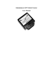
Subminiature GPS Vehicle Tracker
User Manual
Size :45*49*20.8MM
Table of Contents
Chapter I. Foreword
Foreword…………………………………………………………………………..2
I. Overview………………………………………………………………………….2
II. Precautions ……………………………………………………………………….2
Chapter II. Equipment Introduction
Introduction…………………………………………………………3
I. Quick Guide……………………………………………………………………….3
II. Product Characteristics……………………………………………………………5
III. Product Specifications……………………………………………………………6
Chapter III. Introduction of Location Modes
Modes………………………………………………..7
I. Operating instructions of SMS positioning………………………………………..7
II. Operating process for viewing the location through the Internet…………………8
Chapter IV. Operation of Other Functions
Functions…………………………………………………...11
I. Query through mobile phone: ……………………………………………………..11
II. Oil cut-off/power-off functions ……………………………………………………11
………………………………………………………………………11
Chapter V. Instruction Set
Set…
Precautions
Precautions………………………………………………………………………. ……………...18
Chapter I. Foreword
I. Overview
Are you worried about your car being stolen? It is likely that your favorite car attracts car thieves. Although
you may have insured your car, it can not make up for the frustration due to loss of your favorite car…
Are you worried that your cars are deceitfully leased out and can not be recovered? You have many cars for rent
and could have stayed at home comfortably to collect rent, however, the existence of swindlers always make
your feel uneasy, fearing that your car is not returned on schedule and the lessee disappears together with your
car...
Are you racking your brains to improve the operational efficiency of you fleet? It is a widely well-known fact
that the drivers usually disregard considerable waste of company resources in the process of transportation;
however, it is difficult to supervise them closely on the way of transportation. Although a variety of regulations
are formulated, you still can not completely exclude all kinds of false phenomena...
The above problems can be readily solved when the subminiature GPS vehicle tracker is used!
For private cars, this product can help you locate your car in time, so that you can contact the police to recover
your car. There are many successful cases of car recovery thanks to the use of our product. For the cars for rent
purpose, this product can achieve monitoring unknowingly. Just sitting at home, you can know about the
location and driving speed of your car, so that timely recovery of your car can be achieved based on the
monitoring information in case of deceitful lease or theft. For the logistics vehicles, this product can easily
solve many management problems, make the transportation process visible, transparent and controllable,
prevent the drivers’ frauds and irregularities, and improve the utilization of vehicles, save transportation time,
reduce fuel consumption costs, improve goods delivery accuracy and increase customer satisfaction.
Featured by compact size, exquisite design and high location precision, this product can be easily installed and
secured. It is very suitable for prevention of car theft, monitoring and management of logistics vehicles.
Prior to use this product, please take a few minutes to read this user manual, so as to understand the operational
details and get better service.
II. Precautions
1. Please read this manual carefully for correct operation.
2. You need to choose a safe place to install this product, and some dangerous places, such as automobile airbag,
are not suitable for placing this product; otherwise, damage to the driver or passengers may occur.
3. This manual is just for your reference. The contents and operating steps described in this manual may be
different from that of the actual product, please refer to the actual product.
Chapter II. Equipment Introduction
I. Quick Guide
1. Definition of external wiring
Pin 1: External power input (positive), voltage range: DC +6V - +24V.
Pin 2: External power input (negative), connected to GND
Pin 3: Relay control output (positive), voltage: +12V, forbidden from connecting to GND during operation
Pin 4: Relay control output (negative), connected to GND
Pin 5: Debug port RX signal
Pin 6: Debug port TX signal
Pin 7: Emergency alarm signal input SOS; high level under normal circumstances; low level input to enable
SOS alarm.
Pin 8: External status signal input TA; low level under normal circumstances; high level input indicates
occurrence of external events.
Pin 9: Overall power-on signal input ON, high level under normal circumstances; low level input to enable
power-on.
Pin10: External input signal reference ground, connected to GND
Pin11: External microphone input (positive) MIC+
Pin12: External microphone input (negative) MIC-
Pin13: External battery input (positive) BAT+; input voltage: +3.6 - 4.2V; the equipment may be permanently
damaged if the input voltage exceeds the specified range
Pin14: External battery input (negative) BAT-, connected to GND
2. Installation of SIM card
Remove the shell, and install the SIM card as illustrated below:
Beveled
Corner
of SIM Card
Installation of SIM Card
Completed Installation of SIM Card
3. After the SIM card is installed, close the shell tightly, connect the wires and turn on the equipment.
GPS antenna
Notice: The motherboard indicators and the light slots of
the shell shall be aligned, with GPS antenna facing upwards
Note: Install the various functions as needed according to the above wiring diagram. If you only need the most
basic positioning function, just connect to the vehicle power supply.
Optional accessories: cut-off relay, SOS alarm switch, MIC
II. Product Characteristics
● GPS vehicle location
● GSM 850/950//18000/1900MHz
● High sensitivity, highly integrated GPS chip
● Low energy consumption
● Fast signal acquisition
● Support single location and continuous tracking
● Support the fence alarm
● Support location information query through SMS and the Internet
● Locate the user by telephone or through SMS
● Press the SOS button for precise positioning in an emergency
III. Product Specifications
3.1 Technical specifications
GSM module
GSM 850/950//18000/1900MHz
GPS sensitivity
-159dBm
GPS center frequency
L1, 1575.42MHz
GPS positioning accuracy
5 - 25 m
Speed accuracy
0.1 m/s
Time accuracy
In sync with GPS
Default data
WGS-84
Hot start
1s
Cold start
38 s
Maximum altitude
18000 m
Maximum speed
515 m/s
Acceleration of gravity
﹤4g
3.2 Other specifications
Operating temperature
-20---65℃
Humidity
5%---95%
Dimensions (mm)
50*45*21
Voltage
12V - 24V
Average standby current
Less than 80MA
LED
Power supply, work status indication
External alarm switch
SOS
Chapter III. Introduction of Location Modes
Vehicle tracker is a multifunctional GPS positioning product which integrates voice call, SMS positioning and
GPRS positioning services. The operating instructions of the SMS and GPRS positioning are as follows:
I. Operating instructions of SMS positioning
a. Send the message instruction “666+user password” to the terminal, and then the terminal will return a
message about the latitude and longitude (The foreign customers shall try to use this instruction).
b. Send the message instruction “987+user password” to the terminal, and then the terminal will return a
website message. The guardian can log onto the website to check the location information of the user, and a
local map is attached.
c. Send the message instruction “988+user password” to the terminal, and then the terminal will return a
message about the detailed location (To use this function, the GPRS function of the terminal SIM card shall be
subscribed).
For example: When “6660000” is sent, the returned data format is as follows:
Lat: latitude (N/S); latitude value (accurate to five decimal places)
Long: longitude (E/W); longitude value (accurate to five decimal places)
Speed: KM/H (accurate to two decimal places)
Direction: direction of course (accurate to two decimal places)
Date: YYYY-MM-DD
Time: HH: MM: SS (Greenwich time)
BS: base station information
FIX: location status (A/V)
ID: IMEI
STATE: information state
Example of valid data:
Lat: N22.6189
Long: E113.6333
Speed: 0.17 KM/H
Direction: 62.58
Date: 2008-06-17
Time: 09: 39: 45
BS: 27970eb3
FIX: A
ID: 123456789000001
STATE: SMS
Display the location on the map (point-to-point mode)
Open the IE, then key in http://maps.google.com to log onto GOOGLE map website, and input the latitude and
longitude on the upper left corner:
For example: 22.544N, 113.9107E
(Note: If degrees and minutes format is used, the degrees and minutes shall be separated by a space.)
“A” is the specific location displayed on the map.
II. Operating process for viewing the location through the Internet
The user can operate the GPS tracker through the Internet Positioning Service Center (jk.jy100.com) provided
by us. Here, you can check the location information, query costs, historical records, control & management
items, etc.
Operating process:
Log onto the website jk.jy100.com, key in your account number and password, click on Login to enter the
global positioning system (For first logon, please register in our service center).
Enter the operating interface:
Double click to select the terminal, and the terminal position will be displayed on the map directly.
Click on “Get Position” to get the current position.
Click on “Playback” to view the historical track.
Chapter IV. Operation of Other Functions
I. Query through mobile phone
When you call the terminal with a mobile phone (phone number: preset number) and hang up the phone after
ringing 2 - 5 times, the terminal will return a message about the latitude and longitude (To use this function, the
calling number display function of the SIM card shall be subscribed).
II. Oil cut-off/power-off functions
For the installation method, please refer to the installation instructions for the relay.
a. Send the message instruction “223+user password” to the terminal, and then the terminal will return a
message “RF3 OK”. The terminal will turn on the oil cut-off or power-off function.
b. Send the message instruction “233+user password” to the terminal, and then the terminal will return a
message “RF3 OFF”. The terminal will deactivate the oil cut-off or power-off function.
Note: In order to avoid accidents, please take care to use the oil cut-off/power-off instruction (especially during
driving).
Chapter V. Instruction Set
70X+user password, X refers to
Description: The user can switch between the work modes through
the work mode
this instruction. When X is 0, point-to-point mode is set; when X is
3, GRPS mode is set.
Remarks: The default mode of the equipment is 3.
#710#center number#user
password##
#711#phone number 1#phone
number 2#phone number 3#user
password##
#720#alarm mode 0-3#user
password##
Description: The center number setting instruction is set by the
operator for the normal operation of the terminal under the center
mode.
e.g.: #710#1066512000#0000##. After the instruction is executed,
the center number is set as:
1066512000. After successful setting, the terminal returns “710
CONFIG OK” to the mobile phone; if the password is wrong, “710
PASSWORD ER” will be returned.
Set the preset numbers through the message sent by a mobile
phone. After successful setting, the mobile phone will receive the
message “&711&CONFIG OK&&” returned by the terminal.
e.g. 1: #711#13800000001#13800000002#13800000003#0000##
e.g. 2: #711#13800000001###0000##
After successful setting, the terminal returns “711 CONFIG OK” to
the mobile phone; if the password is wrong, “711 PASSWORD
ER” will be returned.
Set the terminal alarm mode:
Alarm mode 0: No alarm
Alarm mode 1: Dialing alarm
Alarm mode 2: Message alarm
Alarm mode 3: Dialing alarm + Message alarm
Note: When the back cover is removed or the SOS alarm switch is
turned on, the terminal will give an alarm according to the preset
alarm mode.
e.g.: #720#3#0000##. After the instruction is executed, the terminal
alarm mode is set as “dialing alarm + message alarm”; when the
alarm message is sent, the first preset number will also be dialed.
After successful setting, the terminal returns “720 CONFIG OK” to
the mobile phone; if the password is wrong, “720 PASSWORD
ER” will be returned.
Note: The default alarm mode of the terminal is 0, that is, no alarm.
#730#interval#number of pieces of #730#0#1#0000##, the GPS is turned off, and the timed return
data returned#user password##
function is deactivated.
#803#fixed IP address#port
number#user password ##
666+user password
Set the server address under the GPRS mode.
Instruction for setting 988 server address:
#988#www.gps02.com#80#user password##
This instruction is used to set the GPRS center server address. The
server address can either be a fixed IP, whose format is xxx. xxx.
xxx. xxx; or a domain name, whose length is less than 64 bytes.
After successful setting, “&803& CONFIG OK &&” will be
returned to the phone; if the password is wrong, “&803&
PASSWORD ER &&” will be returned.
e.g.: #803#119.149.149.114#30000#0000##
It can also be set through the domain name:
e.g.: #803#jk.jy100.com#30000#0000##
Note: This product has a factory-set server address, and the
instruction shall be used with caution.
Single location query; a message about the latitude and longitude
will be returned.
988+user password
Single location query; a message about the specific location will be
returned.
987+user password
Single location query; a website message will be returned. The
guardian can log onto the website to check the location information
of the user, and a local map is attached.
111+user password
Description: After the instruction is executed, the terminal,
according to the settings, will read the data and status information
of the base station in the place where the terminal is located. The
data and status information of the base station will be returned
according to the following format.
#base station information, information of 1st base station n#1-digit
status bit #4-digit user password#requested number##. e.g.:
#25738841, 25708e3d,25738709#1#0000#13900139000##
223+user password
233+user password
#770#new password#old
password##
The terminal activates the oil cut-off or power-off function
The terminal deactivate the oil cut-off or power-off function
Description: After the instruction is executed, the terminal will
change the user password according to the user’s requirements.
After successful setting, “770 CONFIG OK” will be returned to the
phone; if the password is wrong, “770 PASSWORD ER” will be
returned.
e.g.: #770#1111#0000##. After the instruction is executed, the user
#801#letters or numbers (0-20
digits)#user password
password changes from 0000 to 1111.
Change the user name under the GPRS mode
Description: After the instruction is executed, the user name of the
terminal under the GPRS mode will be set according to the
requirements. After successful setting, “801 CONFIG OK” will be
returned to the phone; if the password is wrong, “801 PASSWORD
ER” will be returned.
e.g.: #801#13900139000#0000##
#802#APN (letters or numbers,
4-20 digits)#login user name
(letters or numbers, 4-20
digits)#login password (letters or
numbers, 4-20 digits)#user
password##
After the instruction is executed, the user name is 13900139000.
Set the APN
Description: After the instruction is executed, the terminal APN
under the GPRS mode will be set according to the requirements.
After successful setting, “802 CONFIG OK” will be returned to the
phone; if the password is wrong, “802 PASSWORD ER” will be
returned.
e.g. 1: #802#CMNET###0000##. After the instruction is executed,
the terminal APN is CMNET, the login user name and password
are blank.
e.g. 2: #802#CCDLEN#QIUXIA.21#RX#0000##. After the
instruction is executed, the APN is CCDLEN, the login user name
is QIUXIA.21 and the login password is RX.
Note: The default APN of this product is CMNET.
#751#fence radius
Set the electronic fence.
(meter)#sampling interval
Description: After successful setting, “751 CONFIG OK” will be
(minute)#latitude#longitude#user
returned; if the password is wrong, “751 PASSWORD ER” will be
password##
returned.
e.g.: #751#5000#5#2232.6208N#11354.6378E#0000##
After the instruction is executed, the fence of 5 km radius is set for
the terminal; when the terminal leaves the area, the fence alarm
#752#user password##
message will be sent to the center number.
Read the electronic fence
After the instruction is successfully sent, the terminal reads the
work status data of the fence and returns it to the phone. If the
password is wrong, “&752& PASSWORD ER &&” will be
returned.
e.g.: #752#0000##
The following will be returned: #open:1#lat:
22.54368N#lng:113.91063E#distance:500#time:5#status:2
Wherein, open:1 refers to the activation of the fence, open:0 refers
to the deactivation of the fence.
lat: 22.54368 refers to the latitude (N/S).
lng: 113.91063 refers to the longitude (E/W).
distance: 500 refers to the radius of the fence.
time:5 refers to the sampling interval.
status:2 refers to that the terminal gets valid satellite data, and the
fence works normally.
status:1 refers to that the fence is activated, but the terminal fails to
get valid satellite data.
status:0 refers to that the electronic fence is not set.
#760#user password##
Cancel the electronic fence
Description: After the instruction is executed, the terminal cancels
the fence function. After successful setting, the terminal returns
“760 CONFIG OK” to the phone. If the password is wrong, “760
PASSWORD ER” will be returned.
#901##
#902##
e.g.: #760#0000##
Read the user parameters
Read the GPRS parameters
#904##
#905##
Connect to the GPRS
Disconnect to the GPRS
#921##
Activate the transmission timing
After the instruction is sent, a parameter is added during GRPS
transmission, and the number of minutes calculated by the internal
timer will be sent to the center.
After the transmission timing is activated:
#15-digit EMI code#user name#status bit#password#data type#data
size#base station information#latitude, longitude, speed,
course#data#time#number of timed minutes##
Note: The number of timed minutes is expressed with 7 digits.
Deactivate the transmission timing
After the instruction is sent, the original transmission mode will be
restored.
Normal transmission mode:
#15-digit EMI code#user name#status bit#password#data type#data
size#base station information#latitude, longitude, speed,
course#data#time##
#922##
#923##
Activate the timing control
After the instruction is sent, the timing control will be activated.
When the status bit of the terminal is high, the transmission interval
keeps unchanged; when the status bit is low, the transmission
interval will be adjusted to 1/5 of the normal interval.
#924##
Deactivate the timing control
After the instruction is sent, the timing control will be deactivated.
When the status of the terminal returns to normal, the transmission
interval will not be controlled by the status bit.
#15-digit EMI code#user
name#status
bit#password#LPD#data size#base
station information#latitude,
longitude, speed,
course#data#time##
#15-digit EMI code#user
name#status
bit#password#AUT#data
size#base station
information#latitude, longitude,
speed, course#data#time##
Low-voltage back transmission function, and it is a low-voltage
alarm message.
#15-digit EMI code#user
name#status
bit#password#SOS#data size#base
station information#latitude,
longitude, speed,
course#data#time##
#15-digit EMI code#user
name#status
bit#password#OUT#data
size#base station
information#latitude, longitude,
speed, course#data#time##
SOS alarm function, and it is an SOS alarm message
Lat: latitude (N/S); latitude value
(accurate to five decimal places)
Long: longitude (E/W); longitude
value (accurate to five decimal
places)
Speed: KM/H (accurate to two
decimal places)
Direction: direction of course
(accurate to two decimal places)
This message is returned after the instruction “666+user password”
is sent. When you call the terminal with a mobile phone (phone
number: preset number) and hang up the phone after ringing 2 - 5
times, the terminal will return a message about the latitude and
longitude.
Timed back transmission function, and it is a data message
transmitted back on a timed basis.
It is an alarm message indicating the vehicle is out of the fence.
Date: YYYY-MM-DD
Time: HH: MM: SS (Greenwich
time)
BS: base station information
FIX: location status (A/V)
ID: IMEI
STATE: information state
Precautions:
1. This equipment is of non-waterproof design;
2. The equipment shall work under the GSM/ GPRS network environment;
3. Make sure that there is sufficient balance in the SIM card account, so as to avoid inconvenience;
4. The equipment can not work under power-off status or outside the service area, even you are a registered
user;
5. This equipment supports GPS and GSM/GPRS dual positioning mode;
6. Please use this equipment in the areas permitted by law. Any consequence arising from violation of the
laws shall be solely borne by the user.
Note: As this product adopts a GPS module of high sensitivity, it is normal for drift in the case of weak GPS
signal.