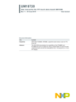
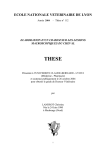
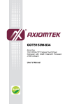
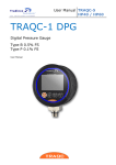
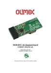
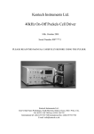
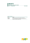
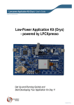
1
UM10505
OM11057 quick start guide
Rev. 2 — 10 April 2013
User manual
Document information
Info
Content
Keywords
Capacitive switch, sensor, proximity switch, OM11057, PCF8885,
PCA8885, PCA8886, evaluation board
Abstract
The OM11057 is an evaluation board which can be used to demonstrate
and evaluate the PCA8886 and PCF8885 capacitive touch and
proximity sensors. The board can be powered by using a Mini USB cable
or battery.
UM10505
NXP Semiconductors
OM11057 quick start guide
Revision history
Rev
Date
Description
v.2
20130410
revised user manual
v.1
20120402
new user manual, first revision
Contact information
For more information, please visit: http://www.nxp.com
For sales office addresses, please send an email to: [email protected]
UM10505
User manual
All information provided in this document is subject to legal disclaimers.
Rev. 2 — 10 April 2013
© NXP B.V. 2013. All rights reserved.
2 of 17
UM10505
NXP Semiconductors
OM11057 quick start guide
1. Introduction
The purpose of this board is to demonstrate the capabilities of NXP’s 8-channel touch
sensor PCF8885 to implement buttons, switch wheels and sliders as well as proximity
sensing with the dual channel PCA8886.
Features:
• Demonstration of the dual channel proximity sensor to wake up the board, one
channel reserved for external sensor pad
• Demonstration of an interface with 4 buttons, a switch wheel and a slider by using an
8-channel sensor circuit in multiplexed mode
•
•
•
•
•
•
•
•
•
•
Enables touch sensitivity through 3 mm acrylic overlay plate
Works stand alone
Can be powered either with 2 AA-batteries or via USB
Feedback with a piezoelectric sounder
Feedback with RGB diodes
Software can be modified using LPC-link
Low-cost Cortex-M0 LPC1114 controller board with 32 kB Flash Memory
PCF8885, 8-channel capacitive sensor
PCA8886, 2-channel proximity sensor. One channel reserved for external sensor
PCF8536 LCD/LED driver
Remark:
The physical properties of any touch experiment are determined by different factors.
These factors are:
• Size of touching entity (single finger, several fingers, palm … hand)
• Speed of approaching object
• Environmental properties like humidity, contamination
By default, the board is configured to:
• Accept a ‘typical human touch’, too fast and too slow movements are screened
out, No fly or turtle will be detected
• As a push-button. If you just touch it slightly, as it would be hot, the capacitance
formed by the finger and the sensor area will be to small (just a few mm2) and
will not be recognized as a touch
The demo board should be put on a desk and not touched on the bottom side as
this would short circuit the sensor inputs and cause false switching!
UM10505
User manual
All information provided in this document is subject to legal disclaimers.
Rev. 2 — 10 April 2013
© NXP B.V. 2013. All rights reserved.
3 of 17
UM10505
NXP Semiconductors
OM11057 quick start guide
2. Quick start
• The demo board is powered up with the power switch
• When the power is turned on, a start-up animation will be shown and the board will be
set in RGB (Red-Green-Blue) mode. This enables the user to obtain a mixture of red,
green and blue with varying intensity of each color.
• A touch on the color selection buttons should be centered on the graphical icon
• The sampling frequency is optimized for a human touch, which means that very quick
or slow touches will be ignored
• For switching between RGB, RED, GREEN and BLUE mode, press the appropriate
button (the display will show RGB channels, RED channel, …)
• In RGB mode, the control is similar to the living color lamp from Philips. By using the
switch wheel, the LCD backlight will sweep through the entire light spectrum, and the
slider will do the same for the control panel lighting. In RGB mode, there is no end and
no beginning, so the wheel can be turned indefinitely in both directions (same
principle for the slider). After a certain time, you will end up at the same color of
course.
• When navigating in the RGB mode, if one of the colors RED, GREEN or BLUE is
chosen, the scroll wheel and the slider will only affect the intensity of the color chosen
in the mixture.
• If the board is not touched for 20 seconds, it will switch to sleep mode. The LEDs and
the LCDs are switched off and a little red LED is switched on to indicate that the board
is in sleep mode. In order to wake up the board, approach the board with your hand.
The status of the board will be the same as before sleep mode
connector for external
interaction boards
color
selection
R22, R23
power ON/OFF switch
power source switch
switch wheel
proximity
sensor pad
Fig 1.
slider
PCA8886
OM11057, top view
UM10505
User manual
All information provided in this document is subject to legal disclaimers.
Rev. 2 — 10 April 2013
© NXP B.V. 2013. All rights reserved.
4 of 17
UM10505
NXP Semiconductors
OM11057 quick start guide
CPC
capacitors
Fig 2.
PCF8885
OM11057, bottom view
UM10505
User manual
All information provided in this document is subject to legal disclaimers.
Rev. 2 — 10 April 2013
© NXP B.V. 2013. All rights reserved.
5 of 17
UM10505
NXP Semiconductors
OM11057 quick start guide
3. Board details
3.1 Power options and ON/OFF switch
Figure 1 shows the ON/OFF and power source selection switches. 2 AA batteries, a USB
cable or an external power supply can be used. By default, batteries are used.
3.2 PCF8885
The color selection buttons, the switch wheel, and the slider are connected to the
PCF8885.
3.2.1 Sensitivity and approach speed
The sensitivity of the sensor channels of the PCF8885 is approximately a linear function of
the value of the reservoir capacitors named CPC0 to CPC7, shown in Figure 2.
The specified maximum value for this component is 470 nF and the board is assembled
with this value to allow 3 mm thick acrylic overlay with margin in sensitivity.
The approach speed sensitivity is a parameter that describes the speed of an
approaching object to be detected. This board is optimized for a “human touch” and filters
out everything slower or faster. The approach speed sensitivity is directly set by the
sampling frequency. Reducing the value of the CPC capacitors makes the range of this
speed smaller as the sensitivity would be lower.
The nominal oscillator frequency is 70 kHz, the sampling frequency of the board is
1.914 kHz resulting in a switching time of 33 milliseconds. This time starts when a finger
enters the coverage distance of the sensor pad and as soon as 64 consecutive samples
are counted the output of the sensor is switched. Hence there is no additional time for post
processing of the samples.
3.2.2 Color selection buttons
Fig 3.
UM10505
User manual
Color selection buttons with pairs of interleaved sensor pads
All information provided in this document is subject to legal disclaimers.
Rev. 2 — 10 April 2013
© NXP B.V. 2013. All rights reserved.
6 of 17
UM10505
NXP Semiconductors
OM11057 quick start guide
As shown in Figure 3, the buttons for color selection are made of two interleaved sensor
pads connected to two separate sensor channels. In order to make sure that both
channels are activated, the touch should be centered on the graphical icon engraved on
the acrylic overlay.
3.2.3 Switch wheel
Fig 4.
Switch wheel
The switch wheel is implemented as eight interleaved pairs of sensor pads connected to
eight sensor channels. The touch will be recognized when moving from one to next
segment.
3.2.4 Slider
Fig 5.
Slider
The slider is implemented as seven interleaved pairs of sensor pads connected to eight
sensor channels. The touch will be recognized when moving from one to next segment.
3.3 PCA8886 proximity sensor
The proximity sensor pad is connected to the PCA8886.
3.3.1 Sensitivity and approach speed
The sensitivity for the proximity sensor is set by the CPC capacitor connected to the
PCA8886 as shown in Figure 6. The specified maximum value for this component is
2.5 μF and the board is assembled with this value.
The approach speed sensitivity for proximity sensing is a result of the sampling frequency
and set with the capacitor CLIN which has 47 pF on the board to set a sampling rate of
640 Hz and a switching time of 100 ms.
UM10505
User manual
All information provided in this document is subject to legal disclaimers.
Rev. 2 — 10 April 2013
© NXP B.V. 2013. All rights reserved.
7 of 17
UM10505
NXP Semiconductors
OM11057 quick start guide
CLIN, C11 for
sampling frequency
CPC, C9 for
sensitivity
Fig 6.
Capacitors for sensitivity and sampling frequency
proximity
sensor pad
Fig 7.
UM10505
User manual
Proximity sensor pad
All information provided in this document is subject to legal disclaimers.
Rev. 2 — 10 April 2013
© NXP B.V. 2013. All rights reserved.
8 of 17
UM10505
NXP Semiconductors
OM11057 quick start guide
4. Add-on boards
Two add-and boards are currently available for the OM11057:
OM11057A: This is a board designed to demonstrate high sensitivity allowing thick
overlays (5 mm).
OM11057B: This is a board designed to demonstrate usage of multiplexing on a flex print
board.
4.1 OM11057A
Key features:
• Two PCF8885 packages: One driving buttons, the other driving a slider
• Through holes in the buttons for backlight
• PCA9535PW (a GPIO expander) drives the 16 LEDs mounted on the reverse side of
the board
• Supplied from the OM11057 main board through K2 or with external power through
K3
• This board is also prepared to be connected to an external I2C master through K3
K3
K2
Fig 8.
UM10505
User manual
OM11057A
All information provided in this document is subject to legal disclaimers.
Rev. 2 — 10 April 2013
© NXP B.V. 2013. All rights reserved.
9 of 17
xxxxxxxxxxxxxxxxxxxxx xxxxxxxxxxxxxxxxxxxxxxxxxx xxxxxxx x x x xxxxxxxxxxxxxxxxxxxxxxxxxxxxxx xxxxxxxxxxxxxxxxxxx xx xx xxxxx
xxxxxxxxxxxxxxxxxxxxxxxxxxx xxxxxxxxxxxxxxxxxxx xxxxxx xxxxxxxxxxxxxxxxxxxxxxxxxxxxxxxxxxx xxxxxxxxxxxx x x
xxxxxxxxxxxxxxxxxxxxx xxxxxxxxxxxxxxxxxxxxxxxxxxxxxx xxxxx xxxxxxxxxxxxxxxxxxxxxxxxxxxxxxxxxxxxxxxxxxxxxxxxxx xxxxxxxx
xxxxxxxxxxxxxxxxxxxxxxxxx xxxxxxxxxxxxxxxxxxxx xxx
NXP Semiconductors
UM10505
User manual
Rev. 2 — 10 April 2013
All information provided in this document is subject to legal disclaimers.
UM10505
OM11057A circuit diagram
OM11057 quick start guide
10 of 17
© NXP B.V. 2013. All rights reserved.
Fig 9.
UM10505
NXP Semiconductors
OM11057 quick start guide
4.1.1 Operation with OM11057A
The PCF8885 IC on the main board has to be disconnected from the I2C bus by removing
the jumpers on the R22 and R23 positions. J2 and J3 shall be inserted to use the batteries
to supply the add-on board.
The operation is simple: A touch on the buttons is indicated with the LED being switched
on. At the same time the choice will be displayed on the display on the main board.
Moving a finger on the slider will turn on the LED corresponding to the pair of channels
activated at the moment and as soon as the finger moves away, the LED will switch off.
4.1.2 Operation via external I2C master
The add-on board can also be operated through the I2C connector K3 (see Figure 8 and
Figure 10). 3.3 V or 5 V may be used for supply. In this case only the INT and SLEEP pins
of IC1 are wired to the connector and IC2 through the I2C bus.
Fig 10. OM11057A I2C connector
4.2 OM11057B
Key features:
• This flex print board has been designed to demonstrate implementation of 14 touch
buttons by multiplexing the 8 channels of the automotive PCA8885
• PCA8885 is configured in 2-key mode such that two sensor pads creating a button
have to be touched in order to report a capacitive event
• Dimension of the board: 190 mm × 296 mm
• There is an opening for backlighting LEDs in the middle of the buttons
UM10505
User manual
All information provided in this document is subject to legal disclaimers.
Rev. 2 — 10 April 2013
© NXP B.V. 2013. All rights reserved.
11 of 17
UM10505
NXP Semiconductors
OM11057 quick start guide
a. Top view
b. Bottom view
Fig 11. OM11057B
UM10505
User manual
All information provided in this document is subject to legal disclaimers.
Rev. 2 — 10 April 2013
© NXP B.V. 2013. All rights reserved.
12 of 17
UM10505
NXP Semiconductors
OM11057 quick start guide
4.2.1 Operation with OM11057B
This flex print can be supplied and operated with OM11057 as shown below. A touch on
one of 14 buttons is indicated by displaying the corresponding function name on the
display of OM11057 and a click sound with a piezzo electric buzzer will be generated as
well.
Fig 12. OM11057B flex connector
4.2.2 Operation via external I2C master
This add-on board can also be operated by an I2C master. Either 3.3 V or 5 V can be used
as supply. The INT and SLEEP pins are wired to optional pins of the connector through
R11, R12, R13, and R14.
If the SLEEP pin is not used, it has to be wired to GND or decoupled with several
hundred nF capacitance. Otherwise, this pin will catch up disturbances such that the
sensor IC fails.
UM10505
User manual
All information provided in this document is subject to legal disclaimers.
Rev. 2 — 10 April 2013
© NXP B.V. 2013. All rights reserved.
13 of 17
UM10505
NXP Semiconductors
OM11057 quick start guide
5. References
UM10505
User manual
[1]
PCA8886 — Dual channel capacitive proximity switch with auto-calibration and
large voltage operating range, Data Sheet
[2]
PCF8885 — Capacitive 8-channel proximity switch with auto-calibration
and very low-power consumption, Data Sheet
All information provided in this document is subject to legal disclaimers.
Rev. 2 — 10 April 2013
© NXP B.V. 2013. All rights reserved.
14 of 17
UM10505
NXP Semiconductors
OM11057 quick start guide
6. Legal information
6.1
Definitions
Draft — The document is a draft version only. The content is still under
internal review and subject to formal approval, which may result in
modifications or additions. NXP Semiconductors does not give any
representations or warranties as to the accuracy or completeness of
information included herein and shall have no liability for the consequences of
use of such information.
6.2
Disclaimers
Limited warranty and liability — Information in this document is believed to
be accurate and reliable. However, NXP Semiconductors does not give any
representations or warranties, expressed or implied, as to the accuracy or
completeness of such information and shall have no liability for the
consequences of use of such information. NXP Semiconductors takes no
responsibility for the content in this document if provided by an information
source outside of NXP Semiconductors.
In no event shall NXP Semiconductors be liable for any indirect, incidental,
punitive, special or consequential damages (including - without limitation - lost
profits, lost savings, business interruption, costs related to the removal or
replacement of any products or rework charges) whether or not such
damages are based on tort (including negligence), warranty, breach of
contract or any other legal theory.
Notwithstanding any damages that customer might incur for any reason
whatsoever, NXP Semiconductors’ aggregate and cumulative liability towards
customer for the products described herein shall be limited in accordance
with the Terms and conditions of commercial sale of NXP Semiconductors.
Right to make changes — NXP Semiconductors reserves the right to make
changes to information published in this document, including without
limitation specifications and product descriptions, at any time and without
notice. This document supersedes and replaces all information supplied prior
to the publication hereof.
Suitability for use — NXP Semiconductors products are not designed,
authorized or warranted to be suitable for use in life support, life-critical or
safety-critical systems or equipment, nor in applications where failure or
malfunction of an NXP Semiconductors product can reasonably be expected
to result in personal injury, death or severe property or environmental
damage. NXP Semiconductors and its suppliers accept no liability for
inclusion and/or use of NXP Semiconductors products in such equipment or
applications and therefore such inclusion and/or use is at the customer’s own
risk.
Applications — Applications that are described herein for any of these
products are for illustrative purposes only. NXP Semiconductors makes no
representation or warranty that such applications will be suitable for the
specified use without further testing or modification.
Customers are responsible for the design and operation of their applications
and products using NXP Semiconductors products, and NXP Semiconductors
accepts no liability for any assistance with applications or customer product
design. It is customer’s sole responsibility to determine whether the NXP
Semiconductors product is suitable and fit for the customer’s applications and
products planned, as well as for the planned application and use of
customer’s third party customer(s). Customers should provide appropriate
design and operating safeguards to minimize the risks associated with their
applications and products.
NXP Semiconductors does not accept any liability related to any default,
damage, costs or problem which is based on any weakness or default in the
customer’s applications or products, or the application or use by customer’s
third party customer(s). Customer is responsible for doing all necessary
testing for the customer’s applications and products using NXP
UM10505
User manual
Semiconductors products in order to avoid a default of the applications and
the products or of the application or use by customer’s third party
customer(s). NXP does not accept any liability in this respect.
Export control — This document as well as the item(s) described herein
may be subject to export control regulations. Export might require a prior
authorization from competent authorities.
Non-automotive qualified products — Unless this data sheet expressly
states that this specific NXP Semiconductors product is automotive qualified,
the product is not suitable for automotive use. It is neither qualified nor tested
in accordance with automotive testing or application requirements. NXP
Semiconductors accepts no liability for inclusion and/or use of
non-automotive qualified products in automotive equipment or applications.
In the event that customer uses the product for design-in and use in
automotive applications to automotive specifications and standards, customer
(a) shall use the product without NXP Semiconductors’ warranty of the
product for such automotive applications, use and specifications, and (b)
whenever customer uses the product for automotive applications beyond
NXP Semiconductors’ specifications such use shall be solely at customer’s
own risk, and (c) customer fully indemnifies NXP Semiconductors for any
liability, damages or failed product claims resulting from customer design and
use of the product for automotive applications beyond NXP Semiconductors’
standard warranty and NXP Semiconductors’ product specifications.
Evaluation products — This product is provided on an “as is” and “with all
faults” basis for evaluation purposes only. NXP Semiconductors, its affiliates
and their suppliers expressly disclaim all warranties, whether express, implied
or statutory, including but not limited to the implied warranties of
non-infringement, merchantability and fitness for a particular purpose. The
entire risk as to the quality, or arising out of the use or performance, of this
product remains with customer.
In no event shall NXP Semiconductors, its affiliates or their suppliers be liable
to customer for any special, indirect, consequential, punitive or incidental
damages (including without limitation damages for loss of business, business
interruption, loss of use, loss of data or information, and the like) arising out
the use of or inability to use the product, whether or not based on tort
(including negligence), strict liability, breach of contract, breach of warranty or
any other theory, even if advised of the possibility of such damages.
Notwithstanding any damages that customer might incur for any reason
whatsoever (including without limitation, all damages referenced above and
all direct or general damages), the entire liability of NXP Semiconductors, its
affiliates and their suppliers and customer’s exclusive remedy for all of the
foregoing shall be limited to actual damages incurred by customer based on
reasonable reliance up to the greater of the amount actually paid by customer
for the product or five dollars (US$5.00). The foregoing limitations, exclusions
and disclaimers shall apply to the maximum extent permitted by applicable
law, even if any remedy fails of its essential purpose.
Translations — A non-English (translated) version of a document is for
reference only. The English version shall prevail in case of any discrepancy
between the translated and English versions.
6.3
Licenses
ICs with capacitive sensing functionality
This NXP Semiconductors IC is made under license to European Patent
No. 0723339, owned by EDISEN - SENSOR SYSTEME GmbH & CO KG
and counterparts. Any license fee is included in the purchase price.
6.4
Trademarks
Notice: All referenced brands, product names, service names and trademarks
are the property of their respective owners.
All information provided in this document is subject to legal disclaimers.
Rev. 2 — 10 April 2013
© NXP B.V. 2013. All rights reserved.
15 of 17
UM10505
NXP Semiconductors
OM11057 quick start guide
7. Figures
Fig 1.
Fig 2.
Fig 3.
OM11057, top view . . . . . . . . . . . . . . . . . . . . . . . .4
OM11057, bottom view . . . . . . . . . . . . . . . . . . . . .5
Color selection buttons with pairs of interleaved
sensor pads . . . . . . . . . . . . . . . . . . . . . . . . . . . . . .6
Fig 4. Switch wheel . . . . . . . . . . . . . . . . . . . . . . . . . . . . .7
Fig 5. Slider . . . . . . . . . . . . . . . . . . . . . . . . . . . . . . . . . . .7
Fig 6. Capacitors for sensitivity and sampling frequency.8
Fig 7. Proximity sensor pad . . . . . . . . . . . . . . . . . . . . . . .8
Fig 8. OM11057A . . . . . . . . . . . . . . . . . . . . . . . . . . . . . . .9
Fig 9. OM11057A circuit diagram. . . . . . . . . . . . . . . . . .10
Fig 10. OM11057A I2C connector . . . . . . . . . . . . . . . . . . 11
Fig 11. OM11057B . . . . . . . . . . . . . . . . . . . . . . . . . . . . . .12
Fig 12. OM11057B flex connector . . . . . . . . . . . . . . . . . .13
UM10505
User manual
All information provided in this document is subject to legal disclaimers.
Rev. 2 — 10 April 2013
© NXP B.V. 2013. All rights reserved.
16 of 17
UM10505
NXP Semiconductors
OM11057 quick start guide
8. Contents
1
2
3
3.1
3.2
3.2.1
3.2.2
3.2.3
3.2.4
3.3
3.3.1
4
4.1
4.1.1
4.1.2
4.2
4.2.1
4.2.2
5
6
6.1
6.2
6.3
6.4
7
8
Introduction . . . . . . . . . . . . . . . . . . . . . . . . . . . . 3
Quick start . . . . . . . . . . . . . . . . . . . . . . . . . . . . . 4
Board details . . . . . . . . . . . . . . . . . . . . . . . . . . . 6
Power options and ON/OFF switch . . . . . . . . . 6
PCF8885 . . . . . . . . . . . . . . . . . . . . . . . . . . . . . 6
Sensitivity and approach speed . . . . . . . . . . . . 6
Color selection buttons . . . . . . . . . . . . . . . . . . . 6
Switch wheel. . . . . . . . . . . . . . . . . . . . . . . . . . . 7
Slider . . . . . . . . . . . . . . . . . . . . . . . . . . . . . . . . 7
PCA8886 proximity sensor . . . . . . . . . . . . . . . . 7
Sensitivity and approach speed . . . . . . . . . . . . 7
Add-on boards . . . . . . . . . . . . . . . . . . . . . . . . . . 9
OM11057A . . . . . . . . . . . . . . . . . . . . . . . . . . . . 9
Operation with OM11057A . . . . . . . . . . . . . . . 11
Operation via external I2C master . . . . . . . . . 11
OM11057B . . . . . . . . . . . . . . . . . . . . . . . . . . . 11
Operation with OM11057B . . . . . . . . . . . . . . . 13
Operation via external I2C master . . . . . . . . . 13
References . . . . . . . . . . . . . . . . . . . . . . . . . . . . 14
Legal information. . . . . . . . . . . . . . . . . . . . . . . 15
Definitions . . . . . . . . . . . . . . . . . . . . . . . . . . . . 15
Disclaimers . . . . . . . . . . . . . . . . . . . . . . . . . . . 15
Licenses . . . . . . . . . . . . . . . . . . . . . . . . . . . . . 15
Trademarks. . . . . . . . . . . . . . . . . . . . . . . . . . . 15
Figures . . . . . . . . . . . . . . . . . . . . . . . . . . . . . . . 16
Contents . . . . . . . . . . . . . . . . . . . . . . . . . . . . . . 17
Please be aware that important notices concerning this document and the product(s)
described herein, have been included in section ‘Legal information’.
© NXP B.V. 2013.
All rights reserved.
For more information, please visit: http://www.nxp.com
For sales office addresses, please send an email to: [email protected]
Date of release: 10 April 2013
Document identifier: UM10505