1
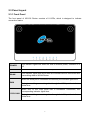
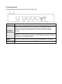
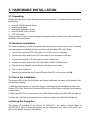
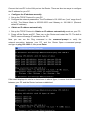
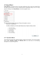
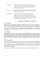
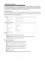
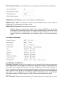
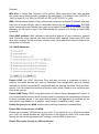
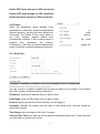
1 TABLE OF CONTENT 1. ABOUT THIS GUIDE................................................................................... 4 1.1 Navigation of the User’s Guide ............................................................ 4 2. PRODUCT OVERVIEW ............................................................................... 5 2.1 Introduction .......................................................................................... 5 2.2 Features .............................................................................................. 5 2.3 Panel Layout........................................................................................ 6 2.3.1 Front Panel ................................................................................. 6 2.3.2 Rear Panel ................................................................................. 7 3. HARDWARE INSTALLATION ..................................................................... 8 3.1 Unpacking............................................................................................ 8 3.2 Hardware Installation ........................................................................... 8 3.3 Check the Installation .......................................................................... 8 3.4 Set up the Computer ........................................................................... 8 4. CONNECTING TO INTERNET .................................................................. 10 4.1 Accessing Web page ......................................................................... 10 4.2 Changing Password .......................................................................... 11 4.3 Setup Wizard ..................................................................................... 12 4.3.1 Operation Mode ........................................................................ 12 4.3.1.1 Gateway .......................................................................... 13 4.3.1.2 Bridge .............................................................................. 13 4.3.1.3 Wireless ISP.................................................................... 13 4.3.2 Time Zone Settings .................................................................. 13 4.3.3 LAN Interface ........................................................................... 14 4.3.4 WAN Interface .......................................................................... 14 4.3.4.1 Static IP ........................................................................... 15 4.3.4.2. DHCP Client ................................................................... 15 4.3.4.3 PPPoE ............................................................................ 16 4.3.4.4 PPTP/L2TP ..................................................................... 16 4.3.5 Basic Settings ........................................................................... 16 4.3.6 Security Settings ...................................................................... 18 4.3.6.1 WEP ................................................................................ 19 4.3.6.2 WPA ................................................................................ 19 4.3.6.3 WPA2 .............................................................................. 19 5. ADVANCED SETTINGS ............................................................................ 21 5.1 System Status .................................................................................... 21 5.2 Operation Mode ................................................................................. 22 5.3 Wireless ............................................................................................. 23 5.3.1 Wireless Status......................................................................... 23 5.3.2 Basic Settings ........................................................................... 23 5.3.3 Repeater Settings ..................................................................... 26 5.3.4 Security Settings ...................................................................... 26 5.3.5 Advanced Settings .................................................................... 27 5.3.6 Multiple APs.............................................................................. 29 5.3.7 Access Control ......................................................................... 29 5.3.8 WDS Settings ........................................................................... 29 2 5.3.9 WPS Settings ........................................................................... 30 5.4 Network ............................................................................................. 31 5.4.1 LAN Interface ........................................................................... 31 5.4.2 WAN Interface .......................................................................... 33 5.4.3 WAN Advanced ........................................................................ 34 5.5 Firewall .............................................................................................. 35 5.5.1 Rule Filter ................................................................................. 35 5.5.2 MAC Filtering............................................................................ 36 5.5.3 URL Filtering............................................................................. 36 5.5.4 Port Forwarding ........................................................................ 36 5.5.5 DMZ ......................................................................................... 37 5.5.6 Connection Limit ....................................................................... 38 5.6 Management...................................................................................... 38 5.6.1 QoS .......................................................................................... 38 5.6.2 Traffic Statistics......................................................................... 39 5.6.3 DDNS ....................................................................................... 40 5.6.4 Time Zone Settings .................................................................. 41 5.6.5 Denial of Service ...................................................................... 41 5.6.6 System Log .............................................................................. 42 5.6.7 Upgrade Firmware .................................................................... 43 5.6.8 Save/Reload Settings ............................................................... 43 5.6.9 Password.................................................................................. 44 3 1. ABOUT THIS GUIDE Thank you very much for purchasing this NG-192 Wireless N Router. This guide will introduce the features of this Router and tell you how to connect, use and configure the Router to connect with Internet. Please follow the instructions in this guide to avoid affecting the Router’s performance by improper operation. 1.1 Navigation of the User’s Guide Product Overview. Describes the Router, its features and appearance. Hardware Installation. Describes the packaging, the hardware installation and how to set the computer. Connecting to Internet. Tells how you can connect your computer to Internet successfully using the Router. Advanced Settings. Lists all technical functions including Wireless, Network, Firewall and Management of the Router. 4 2. PRODUCT OVERVIEW 2.1 Introduction NG-192 is a combined wired/wireless network connection device that integrates with internet-sharing router and 4-port switch. It complies with the most advanced IEEE 802.11n technology and supports multiple security encryptions, including wireless LAN 64/128-bit WEP, WPA/WPA2, WPA-PSK/WPA2-PSK authentication and TKIP/AES. Besides, IP, URL and MAC address filtering function makes it easy for user management. It supports WPS (Wi-Fi Protected Setup) as well which will allow you to connect to secure network simple and fast. In view of the above, it is really a high performance and cost-effective solution for home and small offices. 2.2 Features Complies with IEEE 802.11n and IEEE 802.11g/b standards for 2.4GHz Wireless LAN. Supports PPPoE, Dynamic IP, PPTP, L2TP and static IP broadband functions. Supports UPnP, DDNS, VPN Pass-Through and DMZ Host. Supports 64/128-bit WEP, WPA/WPA2, WPA-PSK/WPA2-PSK (TKIP/AES) encryption. Built-in firewall supports IP, MAC, URL filtering which makes access and time control flexibly. Built-in DHCP server/client. WDS mode makes it simple for WLAN expansion. Supports WMM for improved audio and video streaming. Connects to secure network easily and fast using WPS. Supports QoS bandwidth control. Offers PoE power supply. Supports remote/local web management. Easy setup. 5 2.3 Panel Layout 2.3.1 Front Panel The front panel of NG-192 Router consists of 8 LEDs, which is designed to indicate connection status. POWER This indicator lights blue when the hub is receives power, otherwise it is off. CPU This indicator blinks blue when Router powered on. WLAN This indicator lights blue when there are wireless devices connected and transmitting data to WLAN Router. When the WAN port is connected successfully the indicator lights blue. WAN During transmitting or receiving data through the WAN port the indicator blinks blue. When one of the LAN ports has a successful connection, the corresponding indicator lights blue. 1/2/3/4 LAN During transmitting or receiving data through the LAN port the indicator blinks blue. 6 2.3.2 Rear Panel The figure below shows the rear panel of NG-192 router. DC IN RST/WPS (two-in-one) The Power socket is where you will connect the power adapter. RST: With the router powered on, use a pin to press and hold the button until the SYS LED becomes quick-flash from slow-flash. And then release the button and wait the router to reboot to its factory default settings. WPS: If you have client devices you can press this button to quickly establish a router and client devices and automatically configure wireless security for your wireless network. WAN This port is where you will connect the DSL/cable Modem, or Ethernet. 1/2/3/4 LAN This port connects the router to local PC. 7 3. HARDWARE INSTALLATION 3.1 Unpacking Please open the box of NG-192 Wireless N Router carefully. The box should contain items listed below: One NG-192 Wireless N Router One Power Adapter One Quick Installation Guide One CD-ROM (User’s Guide) UTP LAN Cable If any package content is found missing or damaged, please contact your local reseller that the Router was purchased. 3.2 Hardware Installation For those computers you wish to connect with Internet by this router, each of the computers must be properly connected with the router through provided UTP LAN Cables. 1. Connect the provided UTP LAN cable to one of the router’s LAN port. 2. Connect the other end of the UTP LAN cable to your computer’s LAN port. 3. Connect the second UTP LAN cable to router’s WAN port. 4. Connect the other end of the UTP LAN cable to ADSL or Modem port. 5. Plug the Power Adapter into the Router and then into an outlet. 6. Turn on your computer. 7. Check and confirm that the Power LED and LAN LED on the router are ON. 3.3 Check the Installation The control LEDs of the WLAN Router are clearly visible and the status of the network link can be seen instantly: 1. With the power source on, once the device is connected to the broadband modem, the Power, CPU, LAN, WLAN and WAN port LEDs of the WLAN Router will light up indicating a normal status. 2. When the WAN Port is connected to the ADSL/Cable modem, the WAN LED will light up. 3. When the LAN Port is connected to the computer system, the LAN LED will light up. 3.4 Set up the Computer The default IP address of the Router is 192.168.0.1, the default Subnet Mask is 255.255.255.0. Both of these parameters can be changed as you want. In this guide, we will use the default values for description. 8 Connect the local PC to the LAN port on the Router. There are then two ways to configure the IP address for your PC. Configure the IP address manually 1. Set up the TCP/IP Protocol for your PC. 2. Configure the network parameters. The IP address is 192.168.0.xxx (“xxx” range from 2 to 254). The Subnet Mask is 255.255.255.0 and Gateway is 192.168.0.1 (Router’s default IP address). Obtain an IP address automatically 1. Set up the TCP/IP Protocol in Obtain an IP address automatically mode on your PC. 2. Power off the Router and PC. Then turn on the Router and restart the PC. The built-in DHCP server will assign IP address for the PC. Now, you can run the Ping command in the command prompt to verify the network connection between your PC and the Router. Open a command prompt, and type in ping 192.168.0.1, then press Enter. If the result displayed is similar to that shown in above figure, it means that the connection between your PC and the Router has been established. 9 If the result displayed is similar to that shown in the above figure, it means that your PC has not connected to the Router successfully. Please check it following below steps: 1. Is the connection between your PC and the Router correct? If correct, the LAN port on the Router and LED on your PC’s adapter should be lit. 2. Is the TCP/IP configuration for your PC correct? Since the Router’s IP address is 192.168.0.1, your PC’s IP address must be within the range of 192.168.0.2 ~ 192.168.0.254, the Gateway must be 192.168.0.1. 4. CONNECTING TO INTERNET This chapter introduces how to configure the basic functions of your router to access Internet. 4.1 Accessing Web page Connect to the Router by typing 192.168.0.1 in the address field of Web Browser. Then press Enter key. It will show up the following page that requires you to enter valid User Name and Password: Enter admin for User Name and Password, both in lower case letters. Then click OK button or press Enter key. Now you will get into the web interface of the device. The Main screen will appear. Note: If the above screen does not prompt, it means that your web-browser has been set to using a proxy. Go to Tools menu>Internet Options>Connections>LAN Settings, in the screen that appears, cancel the Using Proxy checkbox, and click OK to finish it. If the User Name and Password are correct, you can configure the router using the web browser. Please click the Setup Wizard link on the left main menu and the Setup Wizard screen will appear. 10 Now you have logged into the web interface of the router. 4.2 Changing Password First, we recommend that you change the password to protect the security of your router. Please go to Management—Password change the password required to log into your router. User Name: enter the User Name you login. New Password: new password is used for administrator authentication. Confirm Password: new password should be re-entered to verify its accuracy. Note: password length is 8 characters maximum, characters after the 8th position will be truncated. Also once you change the login password, it will be required every time you log into your router. 11 4.3 Setup Wizard Setup Wizard is provided as part of the web configuration utility. Users can simply follow the step-by-step process to get the wireless Router configuration ready to run in 6 easy steps by clicking on the Setup Wizard on the left navigation menu. Then the following screen will appear. Please click next to continue. 4.3.1 Operation Mode This parameter specifies the operating network modes for the Router. This router provides three modes: Gateway, Bridge and Wireless ISP. You could refer to the following description to choose the right one. 12 4.3.1.1 Gateway Generally, this operating mode is selected by default as more and more users choose to access Internet by ADSL/Cable Modem. In this mode, the device works as a Software Router of the LAN, all clients will connect to Internet through this “agent”. If you choose this mode, PCs in four LAN ports share the same IP to ISP through WAN port. You can setup the connection type in WAN page by using PPPoE, DHCP client, PPTP client, L2TP client or Static IP. 4.3.1.2 Bridge In Bridge mode the Router forwards all the network management and data packets from one network interface to the other without any intelligent routing. For simple applications this provides an efficient and fully transparent network solution. WLAN (wireless) and LAN (Ethernet) interfaces belongs to the same network segment that has the same IP address space. WLAN and LAN interfaces form the virtual bridge interface while acting as the bridge ports. 4.3.1.3 Wireless ISP It means Wireless Internet Service Provider. If you need to access Internet through Wi-Fi, you can choose this mode. For example, when you are in a hotel, airport or other public commercial place, you can select wireless ISP to connect to Internet. In this mode, all Ethernet ports are bridged together and the wireless client will connect to ISP access point. 4.3.2 Time Zone Settings Here, you can specify the device’s time zone according to GMT (Greenwich Mean Time). 13 Enable NTP client update: NTP means Network Time Protocol which is used to make the computer time synchronized with its server or clock source, such as Quartz and GPS. It can provide high-precision time correction and prevent harmful protocol attack by confirming encryption. You need to check this box to activate this page. Automatically Adjust Daylight Saving: If the Time Zone you choose implements daylight saving time, please select this option. Time Zone Select: Select the Time Zone where the router is located. NTP server: Please choose the corresponding NTP server to get right time. 4.3.3 LAN Interface This page is used to configure the parameters for local area network which connects to the LAN port of your Access Point. IP Address: this is the IP address to be represented by the LAN (including WLAN) interface that is connected to the internal network. This IP will be used for the routing of the internal network (it will be the Gateway IP for all the devices connected on the internal network). Subnet Mask: this is used to define the device IP classification for the chosen IP address range. 255.255.255.0 is a typical netmask value for Class C networks which support IP address range from 192.0.0.x to 223.255.255.x. Class C network netmask uses 24 bits to identify the network and 8 bits to identify the host. Note: If this IP address changed, you can log into the WEB configuration interface only using the new IP address. AND if the new IP address and the original IP address are not in the same segment, the Virtual Server and DMZ Host service will not work. If you need to enable these functions, you will have to reset this IP address. 4.3.4 WAN Interface This interface is used to configure the parameters for Internet network which connects to the WAN port of your Access Point. 14 4.3.4.1 Static IP If your ISP has provided the fixed IP that allows you to access Internet, please choose this option. IP Address: the IP address provided by your ISP. Subnet Mask: This is used to define the device IP classification for the chosen IP address range. 255.255.255.0 is a typical net mask value for Class C networks. Generally it is provided by your ISP. Default Gateway: This is the IP address of the host router that resides on the external network and provides the point of connection to the next hop towards the Internet. This can be a DSL modem, Cable modem, or a WISP gateway router. The router will direct all the packets to the gateway if the destination host is not within the local network. DNS: Domain Name System. Every Internet host must have a unique IP address, also they may have a human-friendly, easy to remember name such as www.yahoo.com. The DNS server converts the user-friendly name into its equivalent IP address. If you select Set DNS Manually, you will have to type in the DNS address by yourself. It is chosen to Attain DNS by default. 4.3.4.2. DHCP Client Dynamic Host Configuration Protocol (DHCP) is a local area network protocol. If you choose this mode, you will get a dynamic IP address from your ISP automatically. 15 4.3.4.3 PPPoE Point-to-Point Protocol over Ethernet (PPPoE) is a virtual private and secure connection between two systems that enables encapsulated data transport. It replies on two widely accepted standards: PPP and Ethernet. It connects users through an Ethernet to the Internet with a common broadband medium, such as wireless device or cable modem. All the users over the Ethernet can share a common connection. If you use ADSL virtual dial-up to connect Internet, please choose this option. User Name: a specific valid ADSL user name provided by your ISP. Password: the corresponding valid password provided by your ISP. 4.3.4.4 PPTP/L2TP PPTP means Point to Point Tunneling Protocol, L2TP means Layer 2 Tunneling Protocol. Both these are VPN connections. If you choose one of them, please type in all the information that your ISP provides for this protocol: 4.3.5 Basic Settings The general wireless settings, such as 802.11 modes, SSID and data rates can be configured in this section. 16 Band-- In fact, this option allows you to choose the radio standard for operation of your Router. 802.11b and 802.11g are old 2.4GHz mode, while 802.11n (2.4GHz and/or 5GHz, in this case, only supports 2.4GHz) is the latest standard based on faster Orthogonal Frequency Division Multiplexing (OFDM) modulation. Here, you can choose the last one 2.4GHz (B+G+N), this mode offers better compatibility. If you choose 2.4 GHz (B)/(G)/(B+G), you cannot setup Channel Width and Control Sideband parameters. Mode--Wireless mode specifies the operating mode of the device. The mode depends on the network topology requirements. There are 4 operating modes supported in this software. AP: This mode allows users with laptop to surf Internet by wireless connection. It’s designed to add wireless function for existed wired Router. It is just suitable for home and small office. Client: If you choose this mode, the Network Type can be changed. But the Channel Number can’t be selected. WDS: Wireless Distribution System means connecting multiple wireless networks to one. It will use two or more wireless bandwidth Router/AP connecting with each other to expand wireless signal to longer distance. This mode is suitable for medium-size networks like school and enterprise network. AP+WDS: WDS allows you to bridge wireless traffic between devices that are operating in Access Point mode. Access Point is usually connected to a wired network (Ethernet LAN) allowing wireless connection to the wired network. By connecting Access Points to one another in an Extend Service Set using the WDS, distant Ethernets can be bridged into a single LAN. Note: If you choose AP/AP+WDS mode, the Network Type can’t be changed. If you select WDS, you can’t change both the Network Type and SSID. Network Type---specifies the network type for your device. How to select one of them depends on whether the wireless network need to share data or peripherals with wired network. 17 Infrastructure: This mode allows Wireless LAN and wired LAN to communicate with each other by one AP. The wireless network bridges to wired network by this mode. If you choose this type, you can’t edit Channel Width and Channel Number. Ad hoc: This mode allows two or more computers with wireless function to send/receive messages from each other. If you choose this type, you can edit all the options. SSID---Service Set Identifier used to identify your 802.11 wireless LAN should be specified while operating in AP or AP+WDS mode. All the client devices within the range will receive broadcast messages from the access point advertising this SSID. Channel Width---This is the spectral width of the radio channel. Supported wireless channel spectrum widths: 20MHz is the standard channel spectrum width (selected by default) 40MHz is the channel spectrum with the width of 40MHz. Control Sideband---This function is to control the sideband of the radio channel. Upper: By default, it is Upper, and the Channel Number is 11. Lower: If you choose Lower, the Channel Number will change to Auto automatically and you can’t change the Control Sideband at the same time. The selectable Channel Number now will range from 1 to 9. Only when you choose other Channel Number you will activate the Control Sideband again. If you choose Upper, the Channel Number selectable will range from 5 to 13. Channel Number---this option provides selectable channel numbers. Enable MAC Clone (Single Ethernet Client): MAC address is the physical address of your computer’s network card. Generally, every network card has one unique Mac address. Since many ISPs only allow one computer in LAN to access Internet, users can enable this function to make more computers surf Internet. Note: only if you choose Client Mode, you can do this operation. 4.3.6 Security Settings Encryption: This Router supports None, WEP, WPA(TKIP), WPA2(AES), WPA2 Mixed security options. Please select one according to the Access Point security policy. 18 4.3.6.1 WEP WEP (Wired Equivalent Privacy) is based on the IEEE 802.11 standard and uses the RC4 encryption algorithm. Enabling WEP allows you to increase security by encryption data being transferred over your wireless network. WEP is the oldest security algorithm, and there are few applications that can decrypt the WEP key in less than 10 minutes. Key Length: 64-bit/128-bit, by default it is 64-bit. 64-bit—For 64 bits WEP key, either 5 ASCII characters, such as 12345 (or 10 hexadecimal digitals leading by 0x, such as 0x414234445.) 128-bit—For 128 bits WEP key, either 13 ASCII characters, such as ABCDEFGHIJKLM (or 26 hexadecimal digits leading by 0x, such as 0x4142434445464748494A4B4C4D). Key Format: If you choose 64 bit, there will be two Key Formats selectable: ASCII (5 characters) and Hex (10 characters). If 128-bit, the Key Formats should comply with ASCII (13 characters) or Hex (26 characters) Key Setting: Please refer to Key Length to set this parameter. 4.3.6.2 WPA Wi-Fi Protected Access (WPA) is the most dominating security mechanism in industry. It is separated into two categories: WPA-personal or called WPA Pre-Share Key (WPA/PSK), and WPA-Enterprise or called WPA/802.1x. TKIP--Temporal Key Integrity Protocol is one cipher for data encryption supported by WPA. 4.3.6.3 WPA2 WPA2 means Wi-Fi Protected Access 2, it is the current most secure method of wireless security and required for 802.11n performance. AES--Advanced Encryption Standard is another cipher for data encryption supported by WPA. Pre-Shared Key Format/Pre-Shared Key: This is a pre-defined key used for encryption 19 during data transmission. It has two formats: Passphrase and Hex (64 characters). Then you need to enter the Pre-Shared Key, either 8~63 ASCII characters, such as 012345678..(or 64 Hexadecimal digits leading by 0x, such as “0x321253abcde…”). After all the above settings, please click Finished button, then page with below messages will pop up: Now you can surf Internet and enjoy the best wireless experience brought by this router. 20 5. ADVANCED SETTINGS This chapter allows users to configure advanced settings includes Wireless, Network, Firewall and Management. These settings are only for more technically advanced users who have sufficient knowledge about wireless LAN. Also they should not be changed unless you know what effect the changes will have on your wireless router. 5.1 System Status The System Status provides basic network settings of this Router, including LAN, WAN and Wireless configuration. Also, you could get the current running firmware version or firmware related information from this presentation. System Uptime: show how long the system has run. Firmware Version: display the current firmware version of the router. Build Time: the time when the firmware built. Wireless Configuration Network Type: the network mode you’ve selected. Band: the current band the router is working at. SSID: Service Set Identifier of this wireless network. Channel Number: the current Channel Number. Encryption: the encryption method of this router. BSSID: Basic SSID. Associated Clients: display the number of associated clients. 21 LAN Attain IP Protocol: display the way to get IP Address. IP Address: display the IP address of the LAN interface. Subnet Mask: show the subnet mask address of the LAN interface. Default Gateway: this is the IP address of the router. DHCP: display the current status of DHCP server of the LAN interface. MAC Address: show the MAC address of the LAN interface. WAN Configuration Attain IP Protocol: display the way to get IP Address. IP Address: show the IP address of the WAN interface. Subnet Mask: display the subnet mask of the WAN interface. Default Gateway: display the assigned IP address of the default gateway. MAC Address: display the MAC address of the WAN interface. 5.2 Operation Mode We have discussed this on P14 Setup Wizard. If you want to change the mode, you can change it here. And then click Apply to make it work. 22 5.3 Wireless The general wireless settings, such as 802.11 modes, SSID and data rates can be configured in this section. Also some more advanced settings can be setup here. 5.3.1 Wireless Status This page displays the current wireless status of the router. 5.3.2 Basic Settings On this page, you could configure the parameters for Wireless LAN clients that may connect to your Access Point. 23 Country: please choose the country where you’re located. By default, it is Argentina. Band: this option allows you to choose the radio standard for operation of your Router. 802.11b and 802.11g are old 2.4GHz mode, while 802.11n is the latest standard based on faster Orthogonal Frequency Division Multiplexing (OFDM) modulation. Here, by default, the 2.4 GHz (B+G+N) mode is selected, this mode offers better compatibility. Mode: Wireless mode specifies the operating mode of the device. The mode depends on the network topology requirements. There are 4 operating modes supported in this software. AP: This mode allows users with laptop to surf Internet by wireless connection. It’s designed to add wireless function for existed wired Router. This mode is just suitable for home and small offices. Client: If you choose this mode, the Network Type can be changed. But the Channel Number can’t be selected. WDS: Wireless Distribution System means connecting multiple wireless networks to one. It will use two or more wireless bandwidth Router/AP connecting with each other to expand wireless signal to longer distance. This mode is suitable for medium-size networks like school and enterprise network. AP+WDS: WDS allows you to bridge wireless traffic between devices that are operating in Access Point mode. Access Point is usually connected to a wired network (Ethernet LAN) allowing wireless connection to the wired network. By connecting Access Points to one another in an Extend Service Set using the WDS, distant Ethernets can be bridged into a single LAN. Note: If you choose AP/AP+WDS mode, the Network Type can’t be changed. If you select 24 WDS, you can’t change both the Network Type and SSID. Network Type: specifies the network type for your device. How to select one of them depends on whether the wireless network need to share data or peripherals with wired network. Infrastructure: this mode allows Wireless LAN and wired LAN to communicate with each other by one AP. The wireless network bridges to wired network by this mode. If you choose this type, you can’t edit Channel Width and Channel Number. Ad hoc: this mode allows two or more computers with wireless function to send/receive messages from each other. If you choose this type, you can edit all the options. SSID: Service Set Identifier used to identify your 802.11 wireless LAN should be specified while operating in AP or AP+WDS mode. All the client devices within the range will receive broadcast messages from the access point advertising this SSID. Channel Width: this is the spectral width of the radio channel. Supported wireless channel spectrum widths: 20MHz is the standard channel spectrum width. 40MHz is the channel spectrum with the width of 40MHz (selected by default). Control Sideband: this function is to control the sideband of the radio channel. Upper: By default, it is Upper, and the Channel Number is 11. Lower: If you choose Lower, the Channel Number will change to Auto automatically and you can’t change the Control Sideband at the same time. The selectable Channel Number now will range from 1 to 9. Only when you choose other Channel Number you will activate the Control Sideband again. If you choose Upper, the Channel Number selectable will range from 5 to 13. Channel Number: this option provides selectable channel numbers. Broadcast SSID: enable this function will allow others search for your SSID and connect to your wireless network. WMM: it is an abbreviation of Wi-Fi Multimedia. It defines the priority levels for four access categories derived from 802.1d (prioritization tabs). The categories are designed with specific types of traffic, voice, video, best effort and low priority data. Associated Client: Only if you choose AP or AP+WDS Mode, you can activate this button and check the MAC address, transmission, reception packet counters and encrypted status for each associated wireless client. See below: 25 Enable MAC Clone: MAC address is the physical address of your computer’s network card. Generally, every network card has one unique Mac address. Since many ISPs only allow one computer in LAN to access Internet, users can enable this function to make more computers surf Internet. Note: only if you choose Client Mode, you can do this operation. 5.3.3 Repeater Settings \ You can choose to enable Repeater interface and click Apply, then you can edit SSID number. Mode: you can’t change this value. It depends on the mode you choose on Basic Settings. SSID: enter the SSID of extended interface. Site Survey: utility will search for wireless networks in range on all the supported channels while device is operating in Access Point. 5.3.4 Security Settings This page enables you to set wireless security method that control how the subscriber station associates to a wireless device and encrypts/decrypts data. Most of the parameters we have discussed on P20 Setup Wizard, if you want to change the settings, you can reset here. 26 802.1x Authentication: if you check this box, you need to provide the below information: RADIUS Server IP Address: enter the IP address of RADIUS server. RADIUS Server Port: the UDP port number that the RADIUS server that is used to authenticate the messages sent between them. RADIUS Server Password: the password of the port. RADIUS: Remote Authentication Dial-In User Service (RADIUS) is a security authentication client/server protocol that supports authentication, authorization and accounting, which is widely used by Internet Service Provides. It is the most common method of authenticating and authorizing dial-up and tunneled network users. 5.3.5 Advanced Settings Fragment Threshold: specifies the maximum size for a packet before data is fragmented into multiple packets. The range is 256-2346 bytes. Setting the Fragment Threshold too low may result in poor network performance. The use of fragment can increase the reliability of frame transmissions. Because of sending smaller frames, collisions are much less likely to occur. However, lower values of the Fragment Threshold will result in lower throughput as well. Minor or no modifications of the Fragmentation Threshold value is recommended while default setting of 2346 is optimum in most of the wireless network use cases. RTS Threshold: determines the packet size of a transmission and, through the use of an 27 access point, helps control traffic flow. The range is 0-2347 bytes. The default value is 2347, which means that RTS is disabled. RTS/CTS (Request to Send / Clear to send) are the mechanism used by the 802.11 wireless networking protocols to reduce frame collisions introduced by the hidden terminal problem. RTS/CTS packet size threshold is 0-2347 bytes. If the packet size the node wants to transmit is larger than the threshold, the RTS/CTS handshake gets triggered. If the packet size is equal to or less than threshold the data frame gets sent immediately. System uses Request to Send/Clear to send frames for the handshake that provide collision reduction for an access point with hidden stations. The stations are sending a RTS frame first while data is sent only after a handshake with an AP is completed. Stations respond with the CTS frame to the RTS, which provide clear media for the requesting station to send the data. CTS collision control management has a time interval defined during which all the other stations hold off the transmission and wait until the requesting station will finish transmission. Beacon Interval: By default, it is set to 100ms. Higher Beacon interval will improve the device’s wireless performance and is also power-saving for client side. If this value set lower than 100ms, it will speed up the wireless client connection. Preamble Type: this option is to define the length of the sync field in an 802.11 packet. Most modern wireless network uses shot preamble with 56 bit sync filed instead of long preamble with 128 bit sync filed. However, some original 11b wireless network devices only support long preamble. IAPP:Inter-Access Point Protocol is designed for the enforcement of unique association throughout an ESS (Extended Service Set) and for secure exchange of station’s security context between current access point (AP) and new AP during handoff period. It is enabled by default. Protection: it is disabled by default. Aggregation: A part of the 802.11n standard. It allows sending multiple frames per single access to the medium by combining frames together into one larger frame. It creates the larger frame by combining smaller frames with the same physical source and destination end points and traffic class (i.e. QoS) into one large frame with a common MAC header. It is enabled by default. Frames—determine the number of frames combined on the new larger frame. Bytes—determine the size (in Bytes) of the larger frame. Short GI: short Guide Interval. It is to assure the safety of propagation delays and reflections for the sensitive digital data. WLAN Partition: divides the WLAN to several parts. 20/40MHz Coexist: enable this function will make the device select the channel with better performance automatically. It is enabled by default. RF Output Power: you can select the output power of the wireless device. The default 28 value is 100%. It will deliver the best performance of the device. 5.3.6 Multiple APs This page allows you to set multiple APs. 5.3.7 Access Control Access Control Mode: you could select Allow List or Deny List according to your requirement. MAC Address: you could enter the MAC Address that you want to allow or deny. Comment: simply describe the reason why you allow or deny this MAC address. Current Access Control List: after you enter the MAC address and click Apply button, this list will display all related information. You can also delete some or all of them by clicking buttons. 5.3.8 WDS Settings WDS means Wireless Distribution System. It is a protocol for connecting two access points wirelessly. Usually, it can be used for the following application: 1. Provide bridge traffic between two LANs though the air. 2. Extend the coverage range of a WLAN. To meet the above requirement, you must set these APs in the same channel and set MAC address of other APs which you want to communicate with in the table and then enable the WDS. 29 Only if you have chosen WDS/AP+WDS mode, you can enable this function. MAC Address: the other AP’s MAC Address that you want to communicate with. Data Rate: please choose the transmission data rate. Comment: describes the reason why you want to communicate with others. Set Security: click this button you can set security rules for WDS. The encryption we have discussed before. You could refer to Security Settings. Show Statistics: this page shows you detailed transmission/receiving packets. See below: 5.3.9 WPS Settings WPS (Wi-Fi Protected Setup) provides easy procedure to make network connection between wireless station and wireless access point with the encryption of WPA and WPA2. It is enabled by default. 30 WPS Status: Display related system information for WPS. If the wireless security (encryption) function of the router is properly configured, you can see “Configured” chosen. By default, it is UnConfigured selected. Self-PIN Number: it will show the PIN Number of your device. Push Button Configuration: click Start PBC to invoke Push-Button style WPS setup procedure. The router will wait for WPS requests from wireless clients about two minutes. The WPS LED on the router will blink fast when WPS is in progress. It will return to normal condition after two minutes. (You need to setup WPS within two minutes.) Client Pin Number: please input the PIN code specified in wireless client you wish to connect, and click Start PIN button. The WPS LED on the router will blink fast when WPS is in progress. It will return to normal condition after two minutes. (You need to setup WPS within two minutes) 5.4 Network This item contains settings for LAN interface, interface and WAN Advanced. Only if you set parameters correct, you can make sure your in your LAN can access Internet. Please follow instructions to configure. WAN these computers the below 5.4.1 LAN Interface Local Area Network (LAN) is a group of subnets regulated and ruled by router. The design of network structure is related to what type of public IP addresses coming from your ISP. This page allows you to configure the parameters for LAN which connects to the LAN port of your Access Point. 31 IP Address: this is the IP addresses to be represented by the LAN (including WLAN) interface that is connected to the internal network. This IP will be used for the routing of the internal network (it will be the Gateway IP for all the devices connected on the internal network). Note: If this IP address changed, you can log into the WEB configuration interface only using the new IP address. AND if the new IP address and the original IP address are not in the same segment, the Virtual Server and DMZ Host service will not work. If you need to enable these functions, you will have to reset this IP address. Subnet Mask: this is used to define the device IP classification for the chosen IP address range. 255.255.255.0 is a typical netmask value for Class C networks which support IP address range from 192.0.0.x to 223.255.255.x. Class C network netmask uses 24 bits to identify the network and 8 bits to identify the host. Default Gateway: this is the IP address of the router. DHCP: you can disable this function or choose DHCP server/client. If you select server, all the computers connected to this router will get the IP address dynamically. Client mode means that this device works as a client and you can’t change the default settings on this page. DHCP Client Range: the range of IP addresses that will be assigned to each computer connected with the router. DHCP Lease Time: the IP addresses given out by the DHCP server will only be valid for the duration specified by the lease time. Increasing the time ensure client operation without interrupt, but could introduce potential conflicts. Lowering the lease time will avoid potential address conflicts, but might cause more slight interruptions to the client while it will acquire new IP addresses from the DHCP server. The time is expressed in seconds. Static DHCP: click the Set Static DHCP button, you will go to the following page: 32 This page allows you reserve IP addresses, and assign the same IP address to the network device with the specified MAC address any time it requests an IP address. This is almost the same as when a device has a static IP address except that the device must still request an IP address from the DHCP server. Domain Name: this represents the name of your IP address. 802.1d Spanning Tree: Multiple interconnected bridges create larger networks using the IEEE 802.1d Spanning Tree Protocol (STP), which is used for finding the shortest path within the network and to eliminate loops from the topology. If the STP is turned on, the router will communicate with other network devices by sending and receiving Bridge Protocol Data Units (BPDU). STP should be turned off (selected by default) when this router is the only bridge on the LAN or when there are no loops in the topology as there is no sense for the bridge to participate in the Spanning Tree Protocol in this case. 5.4.2 WAN Interface This page is used to configure the parameters for Internet network which connects to the WAN port of your Access Point. Most of the settings we have discussed on P16 Setup Wizard. If you want to change any parameters, please reset here and click Apply button. WAN Access Type: there are five modes provided to allow you to access Internet. Please choose the appropriate one according to the information from your ISP (Internet Service 33 Provider). MTU Size: It means Max Transmit Unit for packet. When using slow links, large packets can cause some delays thereby increasing lag and latency. The default value of DHCP is 1492, for static IP, it is 1500, for PPPoE is 1452, for PPTP/L2TP is 1460. DNS: Domain Name System. Every Internet host must have a unique IP address, also they may have a human-friendly, easy to remember name such as www.yahoo.com. The DNS server converts the user-friendly name into its equivalent IP address. If you select Set DNS Manually, you will have to type in the DNS address by yourself. It is chosen to Attain DNS by default. Clone MAC Address: MAC address is the physical address of your computer’s network card. Generally, every network card has one unique MAC address. Since many ISPs only allow one computer in LAN to access Internet, users can enable this function to make more computers surf Internet. 5.4.3 WAN Advanced Enable UPnP: the UPnP (Universal Plug and play) protocol is supported to bring to network connected devices the ease of installation and configuration which is already available for directly connected PC peripherals with the existing Windows “Plug and Play” system. You can enable this function so that the router doesn’t need to work out which port need to be opened. Enable IGMP Proxy: IGMP is the abbreviation of Internet Group Management Protocol. It is a communication protocol which is mainly used for managing the membership of Internet Protocol multicast groups. If you select this checkbox, the application of multicast will be executed through WAN port. In addition, such function is available in NAT mode. Enable Ping Access on WAN: enable users use Ping command to access WAN. Enable Web Server Access on WAN: Enable the necessary VPN service as you need. If you intend to run a VPN server inside your LAN, you should disable the VPN services of this Router to allow VPN tunnel pass through as well as the appropriate NAT settings, such as DMZ or open port: Enable IPsec pass through on VPN connection 34 Enable PPTP pass through on VPN connection Enable L2TP pass through on VPN connection Enable IPv6 pass through on VPN connection 5.5 Firewall While the broadband users demand more bandwidth for multimedia, interactive applications, distance learning, security has been always the concerned. The firewall of this router helps to you local network against attack from unauthorized outsiders. It also restricts users in network from accessing the Internet. Furthermore, it can filter out specific packets that router to build an unwanted outgoing connection. or most protect the local trigger the 5.5.1 Rule Filter You can choose to enable or disable this function according to your needs. If you enable Rule filter, please provide the below information: IP Address: enter the IP address that you want to filter. Port Range: enter the Port range that you want to filter. Protocol: specify the protocol which this filter rule will apply to. Comment: describe the reason why you want to filter these ports. Just few words are saved there usually. Time Range: set time range to filter the IP or ports. Current Filter Table: this table will list the detailed information about the IP and Ports that you don’t allow to access your router. 35 5.5.2 MAC Filtering On this page, you can add some MAC addresses to be filtered to isolate users’ access from wired LAN. You can choose to enable or disable this function according to your needs. If you enable MAC filtering, please provide the below information: MAC Address: you can enter the MAC addresses that you want to filter. Scan MAC Address: click this button to scan MAC addresses in this LAN. You can choose one or more to filter. Comment: describe the reason why you want to filter these MAC address. Just few words are saved there usually. Current Filter Table: this table will list the detailed information about the MAC addresses that will be filtered. 5.5.3 URL Filtering This page is used to deny LAN users from accessing the internet. Block those URLs which contain keywords listed. You can choose to enable or disable this function according to your needs. If you enable URL filtering, please provide the below information: URL Address: enter the URLs that you don’t allow to access this router. 5.5.4 Port Forwarding Port Forwarding creates a transparent tunnel through a firewall/NAT, granting an access from the WAN side to the particular network service running on the LAN side. These settings are only necessary if you wish to host some sort of server like a web server or mail server on the private local network behind your Gateway’s NAT firewall. 36 You can choose to enable or disable this function according to your needs. If you enable Port forwarding, please provide the below information: IP Address: enter the IP address that you want to forward. Protocol: specify the protocol which this filter rule will apply to. Port Range: enter the port range that you want to forward. Comment: describe the reason why you want to filter these MAC address. Just few words are saved there usually. Current Port Forwarding Table: this table will list the detailed information about the ports that will be forwarded. 5.5.5 DMZ DMZ means Demilitarized Zone. It can be enabled and used as a place where services can be placed such as Web Servers, Proxy Servers and E-mail Servers such that these services can still serve the local network and are at the same time isolated from it for additional security. DMZ is commonly used with the NAT functionality as an alternative for the Port Forwarding while makes all the ports of the host network device be visible form the external network side. You can choose to enable or disable this function according to your needs. If you enable DMZ, please provide the below information: DMZ Host IP Address: type in the IP address of the DMZ host 37 5.5.6 Connection Limit IP Range: set the IP range that you need to limit connection. Connection Limit Num: set the connection limit number. The range is from 1 to 50. Connection Limit List: after you click Apply to make the settings work. This table will display the detailed information about the limit. 5.6 Management For system management, there are several items to know the way of configuration: Status, Password, Configuration Backup, Syslog, Time System, Firmware upgrade. that you have Administrator setup, Reboot 5.6.1 QoS QoS means Quality of Service. Deploying QoS management to guarantee that all applications receive the service levels required and sufficient bandwidth to meet performance expectations is indeed one important aspect of modern enterprise network. Since numerous TCP-based applications tend to continually increase their transmission rate and consume all available bandwidth, we need QoS to control the bandwidth use. On this page, you could set the QoS rules. 38 Manual Uplink Speed: you can set the uplink speed for all LAN computers. Manual Downlink Speed: you can set the downlink speed for all LAN computers. Address Type: here you can choose the limit address type. IP Address: if you choose IP address, please enter the IP address range. MAC Address: if you choose MAC, please enter the MAC address or using Scan Mac Address button. Mode: this option is allow you to set guaranteed minimum bandwidth or restricted maximum bandwidth. Uplink bandwidth: type in the uplink bandwidth. Downlink bandwidth: type in the downlink bandwidth. Comment: describe the reason. Just few words are saved there usually. 5.6.2 Traffic Statistics This page shows the packet counters for transmission and reception regarding to wireless and Ethernet networks. 39 5.6.3 DDNS DDNS means Dynamic Domain Name System. The ISP often provides you with a dynamic IP address when you connect to the Internet via your ISP. It means that the public IP address assigned to your router changes each time you access the Internet. The Dynamic DNS feature lets you assign a domain name to a dynamic WAN IP address. It allows the router to update its online WAN IP address mappings on the specified Dynamic DNS server. Once the router is online, you will be able to use the registered domain name to access the router or internal virtual servers from the Internet. It is particularly helpful if you host a web server, FTP server, or other server behind the router. Before you user the Dynamic DNS feature, you have to apply for free DDNS service to the DDNS service providers. The router provides up to three accounts from three different DDNS service providers. This router supports two service providers: DynDNS and TZO. You could choose to enable or disable DDNS function. If you enable DDNS, you need to provide below information: Service Provider: choose one service provider where you have applied for free DDNS service. Domain Name: type in the host name you registered from the DDNS provider. User Name: enter the User Name or Email you registered from the DDNS provider. Password: enter the Password or Key you set for the User Name. 40 5.6.4 Time Zone Settings This page allows you to maintain the system time by synchronizing with a public time server over the Internet. Most of the settings on this page we have discussed on P15 Setup Wizard. If you want to change, you can reset here and click Apply to make it work. Current Time: it shows the current time by default. Time Zone Select: select the Time Zone where the router is located. 5.6.5 Denial of Service The DoS Prevention functionality helps you to detect and mitigate the DoS attack. The attacks are usually categorized into two types, the flooding-type attacks and the vulnerability attacks. The flooding-type attacks will attempt to exhaust all your system’s resource while the vulnerability attacks will try to paralyze the system by offending the vulnerabilities of the protocol or operation system. The DoS Prevention function enables this router to inspect every incoming packet based on the attack signature database. Any malicious packet that might duplicate itself to paralyze the host in the secure LAN will be strictly blocked and a Syslog message will be sent as warning, if you set up Syslog server. Also this router monitors the traffic. Any abnormal traffic flow violating the pre-defined parameter, such as the number of thresholds, is identified as an attack and the router will activate its defence mechanism to mitigate in a real-time manner. 41 Enable DoS Prevention: check this box to enable DoS prevention function. This page shows the attack types that DoS prevention function can detect: Whole System Flood: SYN ICMP Smurf Whole System Flood: FIN IP Land Whole System Flood: UDP IP Spoof Whole System Flood: ICMP IP TearDrop Per-Source IP Flood: SYN Per-Source IP Flood: FIN PingofDeath TCP Scan Per-Source IP Flood: UDP TCP SynWithData Per-Source IP Flood: ICMP UDP Bomb TCP/UDP PortScan UDP EchoChargen Sensitivity: you can select Low or High sensitivity. You can click Select ALL or Clear ALL to select prevention type. 5.6.6 System Log This page can be used to set remote log server and show the system log. 42 Enable Log: this option enables the registration routine of the system log messages. Be default it is disabled. Below items including system all, wireless, Dos allows you to choose the log type. Enable Remote Log: enables the syslog remote sending function while System log messages are sent to a remote server. Log Server IP Address: this is the host IP address where syslog messages should be sent. 5.6.7 Upgrade Firmware This page allows you to upgrade the Access Point firmware to new version. Please note, DO NOT power off the device during the upload because it may crash the system. Firmware Version: shows the current firmware version. Select File: select the firmware version you want to upgrade on your computer. Click Upload to upgrade the firmware version. 5.6.8 Save/Reload Settings This page allows you to save current settings to a file or reload the settings from the file which was saved previously. Besides, you can reset the current configuration to factory default. 43 Save Settings to File: click Save button to download the current settings of the Access Point to your computer. Load Settings from File: if you want to reload the settings from the file saved before, you could click Choose File button to choose the right file then click Upload button. Reset Settings to Default: this Reset button is provided to allow you to restore the router settings to the default factory settings. Reboot Device: click Reboot to reboot this device. 5.6.9 Password This page allows you to change the password to login web interface of this router. Detailed settings please refer to Changing password. 44