1
POF65
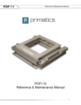
Reference & Maintenance Manual
POF65
Reference & Maintenance Manual
1
POF65
Reference & Maintenance Manual
32114 Mallard Ave.
PO Box 409
Tangent, OR 97389-0409
U.S.A.
Phone:
Fax:
Toll Free:
Web:
E-mail:
[541] 791-9678
[541] 791-9410
[888] 754-3111
www.primatics.com
[email protected]
Manual Revision Information
Publication Date
Mar 2011
12/14/12
1/20/15
Notes
First Release
Revised Specs and travel limits/sensor activation points
New logo
Notice: The descriptions, drawings, and specifications contained herein are subject to change.
Primatics is not responsible for errors or omissions herein or for incidental damages in connection with
the furnishing or use of this information. This document shall not be reproduced, photocopied, or
duplicated, in whole or in part, without prior written approval of Primatics Corporation.
©Copyright 2011 -2015 by Primatics, Inc; All Rights Reserved. Primatics, the Primatics logo, PrimaFlex,
PrimaSeal & SimpleMatch are trademarks of Primatics, Inc.
2
POF65
Reference & Maintenance Manual
Manual Revision Information ............................................................................. 2
1) Overview .......................................................................................................... 4
2) Introduction – About the XY Stage................................................................ 5
3) Personal Safety ............................................................................................... 5
4) Stage & Manual Conventions ........................................................................ 7
4.1) Direction of Motion ............................................................................................................. 7
4.2) Units of Measure ................................................................................................................ 7
5) Installation Preparations ................................................................................ 8
5.1) Linear Motors ..................................................................................................................... 8
5.2) Heat and Humidity.............................................................................................................. 8
5.3) Contamination .................................................................................................................... 9
5.4) Electrical Noise .................................................................................................................. 9
6) Installation Procedures .................................................................................. 9
6.1) Tools you will need............................................................................................................. 9
6.2) Unpacking .......................................................................................................................... 9
6.3) Mounting surface preparation ..........................................................................................10
6.4) Mounting the XY stage .....................................................................................................10
6.5) Electrical Connections......................................................................................................10
6.5.1) Motor Commutation Diagram ........................................................................................12
6.5.2) Encoder Timing Diagram ..............................................................................................12
6.5.3) Encoder Index ...............................................................................................................12
6.5.4) Motor Parameters .........................................................................................................13
6.6) Home and Limit Sensors ..................................................................................................13
6.6.1) Home Options: ..............................................................................................................14
6.7) Limit and Home Switch Adjustment .................................................................................15
6.8) Recommended System Test ............................................................................................15
7) Preventive Maintenance ............................................................................... 16
7.1) Lubrication ........................................................................................................................16
8) Troubleshooting & Service .......................................................................... 17
8.1) Troubleshooting Help .......................................................................................................17
8.2) Service .............................................................................................................................17
3
POF65
Reference & Maintenance Manual
1) Overview
This user guide is designed to help you install and maintain your custom linear positioning stage
application. Follow these steps to ensure correct stage installation and maximum stage life:
Step 1
Review this entire user manual. Become familiar with all installation procedures
prior to integrating your system.
Step 2
Review the safety summary to develop an understanding of standard safety
practices when installing and operating automated equipment.
Step 3
Familiarize yourself with the conventions summary.
Step 4
Review installation procedures. For best results, follow these procedures
carefully.
Step 5
Once you successfully complete all the installation procedures, you will be
ready to install and operate your stage.
Step 6
Review preventive maintenance section for proper lubrication schedule.
4
POF65
Reference & Maintenance Manual
2) Introduction – About the XY Stage
The POF65 is a XY linear stage with large aperture. It incorporates two direct drive brushless
linear motors and high resolution linear encoders in a low profile package. A home switch and
index pulse on each encoder are used for determining a repeatable home position. Forward and
reverse limit switches are encountered at the respective ends of each axis of travel.
Travel
Payload
Orientation
Accuracy
Encoder Resolution
Repeatability
Straightness
Flatness
Orthogonality
Rated speed
Motor type
Limit Sensors
Home Sensor
Encoder type
Cleanroom class
Finish
Height
Width
Weight
Upper axis = ± 65mm
Lower axis = ± 65mm
5kg
Horizontal
± 4um full travel (slope corrected)
0.1um, 0.2um, or 1um
±0.5um, ±0.7um, ±1um (resolution dependent)
+/- 2.5 microns
+/- 2.5 microns
10 arc-sec
600mm/s
Linear motor
2 Normally Closed sensors
Yes, transition in center of travel
linear metal tape scale
10,000
Black Anodize
65 mm
368 x 407 mm
≈17 kg
3) Personal Safety
5
POF65
Reference & Maintenance Manual
Please review before installing your positioning stage
Observe common industrial safety practices when installing and operating automated equipment.
o
Have power connections made by qualified personnel.
o
Keep fingers and other items out of any opening in the stage while it is in operation since
injury or damage may result.
o
Provide a safe access route and adequate room for servicing.
o
Perform the recommended periodic maintenance described in this document.
o
Verify that the work envelope is free of obstructions before the positioning stage is
powered.
o
Insure that you have the feedback wired properly to the controller before applying power
to the positioning stage. Improper feedback connections can cause a motor run-away
condition that has the potential to damage the stage and injure an operator.
o
Only trained operators of the positioning stage should be allowed near the work
environment.
o
If so equipped, identify emergency stop circuits and actuators in the workcell.
o
Note the places in the workcell where pinch points occur, and provide adequate safety
clearance or safety curtain.
o
Never operate the motor in a location that could be splashed by water, exposed to
corrosive or flammable gases or is near combustible substances since this may cause an
electric shock, fire or malfunction.
o
Never touch the motor, driver, or peripheral devices when the power is on or immediately
after the power is turned off. The high temperature of these parts may cause burns.
6
POF65
Reference & Maintenance Manual
4) Stage & Manual Conventions
4.1) Direction of Motion
The positive direction of motion for both axes is defined as shown in Figure 4-1. A positive
direction of motion also signifies the encoder count is increasing. The forward limit switches are
encountered just before the end of travel in the forward direction. The reverse limit operates
similarly in the reverse direction.
Figure 4-1: Positive direction convention
4.2) Units of Measure
Primatics uses the metric system for all specifications and dimensions. All linear dimensions are
specified in millimeters. Accuracy, repeatability, resolution, flatness and straightness for the XY
stage is specified in microns. Load capacity is specified in kilograms and moment capacity is
given in Newton-meters. All torque specifications are given in Newton-meters. Thrust
specifications are given in Newtons.
The following table gives some common conversions into English units:
Metric Unit
English Unit
1 Kilogram equals
0.0685 slug*
1 micron equals
0.0000394 inch
1 millimeter equals
0.0394 inch
1 Newton-meter equals
8.85 in-lbs
1 Newton equals
0.2248 lbs
2
*1 Kg has a weight of 2.205 lb when g = 9.8 m / s
2
*1 Kg has a weight of 2.205 lb when g = 9.8 m / s
7
POF65
Reference & Maintenance Manual
5) Installation Preparations
This section outlines installation environments. Unfavorable installation conditions may cause
electric shock, fire, or breakdown. Certain breakdown situations or malfunctions in particular may
lead to serious injury or other consequences. Assure that the unit is used under the following
installation conditions:
o
o
o
o
o
o
Indoors, free from being splashed by water
No corrosive or inflammable gases present
Well ventilated place, minimum level of dust or waste
An environmental temperature range between 0-40°C, and humidity between 20-80% RH
(location with no condensation) Note - These values show the range in which operation
can be carried out safely, but not the environmental range in which stages accuracy can
be guaranteed. Stage accuracy can be guaranteed at 20°C +/- 1°C.
Location should not be affected by electrical noise.
Location should be where inspection and cleaning can be performed without difficulty.
5.1) Linear Motors
Linear motors have large magnetic flux that can draw ferrous metals inside them from large
distances, destroy magnetic media, and disrupt some electronic circuits. Materials attracted to
the magnets can pinch fingers and cause injury. Great care must be taken when operating less
than 25mm from the surface of the motor.
In addition, braking is difficult for linear motors making them inappropriate for many vertical
applications. Make sure no load is attached to the linear motor stage when stage is first
connected to the electronics. Linear motors can generate large accelerations and improper
wiring to the control system can result in a high-speed crash.
5.2) Heat and Humidity
All positioning stages are assembled and tested at 20°C. Any stage calibrations are also
performed at 20°C. For optimum accuracy the ambient temperature should be maintained at
20°C. Deviations from this nominal temperature may result in degraded accuracy performance.
Large thermal gradients in the interior of the stage can result from motor heat created by high
acceleration moves. Care must be taken to limit the duty cycle of the linear motor to maintain
stage performance. Airflow across the motor will help minimize thermal expansion effects and
increase the allowable duty cycle. This can be accomplished with the POF65 fan kit part number
0-1175-0060.
8
POF65
Reference & Maintenance Manual
5.3) Contamination
Applications in dirty or dusty environments require the electrical, optical and mechanical
components to be protected. The XY series is intended for clean environments free from small
particulates and fluids.
5.4) Electrical Noise
Electrical noise is the corruption of signals carried over low voltage wires. Encoder signals can
be corrupted resulting in spurious encoder counts thus causing the stage to drift. Grounding,
shielding, and spatial separation are all countermeasures to reduce the influences of electrical
noise on performance. You can minimize the potential for electrical noise by observing the
following installation precautions:
o
o
o
Physically separate low voltage conductors from those carrying high voltage.
Ensure that all components are properly grounded.
Ensure that all wiring is properly shielded.
6) Installation Procedures
6.1) Tools you will need
The XY linear positioning stage uses eight M6x18mm socket-head cap screws for the base plate
mounting. The carriage plate has eight M4x0.7 and four M5x0.8 tapped holes for customer
mounting. A 4mm hex key is required to remove the red shipping bracket.
6.2) Unpacking
Carefully remove the stage from its shipping crate and inspect it for evidence of shipping damage.
Report any damage immediately to your authorized dealer. Remove the red shipping clamp from
the stage.
Improper handling of the stage may degrade its performance. Follow these guidelines when
handling and mounting your stage.
1) Do not drop the stage onto its mounting surface. Place the stage gently on the mounting
surface. Impact loads can cause high spots on mounting surfaces, misalignment of drive
components and warping of the base.
2) Do not drill holes into the stage. If additional holes are necessary, contact your local
distributor.
3) Lift the stage by its base structure only. Do not lift by the motor drive assembly.
4) Stage disassembly and alteration, unless specified otherwise, may void warranty.
5) Remove the red shipping bracket prior to use.
9
POF65
Reference & Maintenance Manual
6.3) Mounting surface preparation
The characteristics of the surface the positioning stage is mounted to will have a large effect on
system performance. An accurate and flat positioning stage will conform to the shape of its
mounting surface, therefore a flat mounting surface is required. The flatness and straightness
specifications can be affected under large loads. For best results in maintaining stage
specifications we suggest the following:
1) Use a laboratory Grade AA granite surface plate
2) Before mounting stage, inspect for burrs or dings on the stage mounting surfaces
3) Clean all mounting surfaces with acetone
In the absence of a granite surface plate, we recommend a base plate made of the same material
as the base of the stage. A mounting surface constructed out of a material different from the
stage base material can introduce warping in the stage in the presence of a thermal gradient.
The surface flatness should match the requirements of the application; a good starting point is to
have the mounting surface flat to less than 5-8µm.
6.4) Mounting the XY stage
The XY stage has eight mounting holes that can be accessed by moving the X-Axis and Y-axis to
expose 4 access holes. Figure 6-1 shows the location of these access holes. When tightening
the mounting screws, tighten the center screws first, then radiate outwards.
Figure 6-1: Mounting Hole Access Locations\
th
(4 access hole not shown)
6.5) Electrical Connections
10
POF65
Reference & Maintenance Manual
Electrical connections to the stage are through single 28 pin connector as shown in Table 6-1.
Table 6-1: Electrical Connector, 28pin panel mount
Pin
A
B
C
D
E
F
G
H
J
K
L
M
N
P
R
S
T
U
V
W
X
Y
Z
a
b
c
d
e
Function
Motor A
Motor B
Motor C
Motor Shield
Encoder 5V – power for encoder
Encoder A+ output
Encoder A- output
Encoder B+ output
Encoder B- output
Encoder Shield
12 - 24VDC - for limit & home
DCCOM
Home
Brake release output (24VDC) for optional brake
Brake return for optional brake
Stage Base
Hall V+
Hall VEncoder 0V
Encoder Index +
Encoder Index Forward Limit Switch
Reverse Limit Switch
Signal Shield
Hall A
Hall B
Temperature monitor – connect to DC Common for temperature OK
Hall C
11
POF65
Reference & Maintenance Manual
6.5.1) Motor Commutation Diagram
The following diagram shows the motor signal timing for the Servo Motor option
Figure 6-2: Motor commutation chart
6.5.2) Encoder Timing Diagram
The following diagram shows the encoder signal timing for the Encoder option
Figure 6-3: Timing diagram for the encoder signals
6.5.3) Encoder Index
The linear encoder reference signal (index) is located at the nominal center of travel and
is output in both directions but repeatability is guaranteed only in one phased direction.
The reference mark output is synchronized with the incremental channels, giving it a unit
of resolution pulse width. The encoder index is phased in the negative direction.
Therefore, during a homing routine, the stage should travel to the home vane transition,
and then start searching for the index in the minus direction. It is recommended that the
12
POF65
Reference & Maintenance Manual
homing procedure be performed as part of any power-up sequence to ensure the correct
datum position is recorded.
6.5.4) Motor Parameters
Y-axis
X-axis
(Lower)
(Upper)
Primatics P/N
9-0044-0038 9-0044-0025
Continuous Force (N)1
48
16
Continuous Current (Ampsrms)1
2.0
1.2
Peak Force (N)2
220
83
Peak Current (Ampsrms)2
8.9
6.3
Force Constant (N/Ampsrms)
24.7
13.2
Back EMF Constant (V/m/sec)
24.7
13.2
Resistance (Ω)
4.5
6.4
Inductance (mH)
6
4
Magnetic Pitch (mm)
60.96
60.96
Motor Thermal Resistance (C/W)
1.4
2.6
Stage Thermal Resistance (C/W)
0.75
0.75
1
At 25°C temperature rise 2 At 10% duty cycle and 1 second maximum
6.6) Home and Limit Sensors
The home & limit switches uses reflective sensors located in the stage. A white reflective
strip with black masking is viewed with these reflective sensors. One half of this strip is
covered with a black mask. When the sensor is over the white area, the output signal
conducts current and closes the home switch. When the sensor is over the black, the
switch is open. The home switch is fixed at the factory and cannot be adjusted. End of
travel optical limit switches trigger when the axis is past its nominal travel from center. A
reference index on the encoder is located at the nominal center of travel. The limit
switches and encoder index are fixed at the factory and cannot be adjusted. See Figures
6-4, & 6-5 for clarification.
Each XY stage includes Forward and Reverse Limit sensors and a Home sensor. Figure
6-4 shows the equivalent schematic for these switches.
13
POF65
Reference & Maintenance Manual
Figure 6-4: Equivalent Limit, Home, and Temp circuit schematic
6.6.1) Home Options:
The Home switches are factory configured as the Normally Closed (H1)
configuration.
H1: Switch is closed when carriage is between the negative (reverse)
end of travel and the home transition point. It is open from the transition
point to forward end of travel.
6.6.2) Limit Options:
The Limit switches are factory configured as the Normally Closed (L1)
configuration.
L1: When the carriage is in the normal operating range of travel, both
limit switches are closed. When the carriage encounters a limit the switch
opens. The switch will close again when the carriage is moved away
from the switch.
14
POF65
Reference & Maintenance Manual
6.7) Limit and Home Switch Adjustment
The limit and home switch positions are preset at the factory. The limits are nominally set
to yield slightly more travel than specified in the model configuration. The nominal home
switch transition point is about 2mm to the positive side of the center of travel.
Position (mm)
+71
+66.8
+66.15
+65.5
+65
+2.7
+2.0
+1.3
+1.0
0
-1.0
-65
-65. 5
-66.15
-66.8
-71
Bumper Contact
Forward Limit trips
Nominal travel
Hemisphere
Center of travel (encoder index)
Nominal travel
Reverse Limit trips
Bumper Contact
Figure 6-5: X-axis & Y-axis Limit and Home Sensor Transition Ranges
6.8) Recommended System Test
Before attaching a load or applying power to your stage, verify the encoder and limit
switches are working properly. Move the stage by hand in the positive direction and
verify the encoder count is increasing (see Figure 4-1). Runaway conditions caused by
miswired encoders can result in stage damage and personal injury. Move stage to each
end of travel to ensure limit switches are working properly. When closing the position
loop for the first time, set the torque limit of your controller to a low value and use
conservative tuning gains. Once the control loop is working properly, payloads can be
added to the stage carriage.
15
POF65
Reference & Maintenance Manual
7) Preventive Maintenance
Performing preventive maintenance procedures on your stage will extend its life and
improve its long-term performance.
7.1) Lubrication
Use clean room grease to lubricate the linear guide components. We recommend NSK
grease part #GRS LG2. For low duty cycle applications, it is recommended that the
linear guides are re-greased every six months. High duty cycle applications may require
more frequent re-lubrication. Lubrication intervals depend on duty cycle, load and
ambient conditions. Inspection of the drive train elements may be required to determine
the proper lubrication interval. Primatics offers a grease kit that has all the necessary
hardware to re-lubricate the linear bearings.
On the end of each bearing block is a small hole where grease is injected using a syringe
(see Figure 7-1). Cycle the stage back and forth to distribute the grease and wipe off any
excess.
Figure 7-1: Bearing block lubrication port
16
POF65
Reference & Maintenance Manual
8) Troubleshooting & Service
8.1) Troubleshooting Help
For further assistance contact the factory:
M-F 8AM to 5PM Pacific Time
Phone:
Fax:
Toll Free:
Web:
E-mail:
[541] 791-9678
[541] 791-9410
[888] 754-3111
www.primatics.com
[email protected]
8.2) Service
Should your device require factory service, contact the factory for a Return Materials
Authorization (RMA). When inquiring about an RMA please have the following
information available:
o Your contact information (name, phone, email, address)
o Unit Serial Number
o Symptom of problem
o History of troubleshooting steps already taken
Figure 8-1: Unit Serial Number Location
17