1
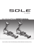
OWNER’S MANUAL
PLEASE CAREFULLY READ THIS ENTIRE MANUAL BEFORE OPERATING
YOUR NEW ELLIPTICAL!
TABLE OF CONTENTS
Important Safety Instructions
3
Important Electrical Information
4
Important Operation Instructions
5
Transport Instructions
5
Assembly Instructions
6
Elliptical Features
13
Operation of Your New Elliptical
14
Programmable Features
17
Using Heart Rate Monitor
23
General Maintenance
25
Exploded View Diagram
26
Parts List
27
ATTENTION
THIS ELLIPTICAL IS INTENDED FOR RESIDENTIAL USE ONLY AND IS
WARRANTED FOR THE APPLICATION. ANY OTHER APPLICATION VOIDS THIS
WARRANTY IN ITS ENTIRETY.
SE869-YE007_1304(SL)A
2
IMPORTANT SAFETY INSTRUCTIONS
WARNING - Read all instructions before using this appliance.
DANGER - To reduce the risk of electric shock disconnect your elliptical from the
electrical outlet prior to cleaning and/or service work.
WARNING - To reduce the risk of burns, fire, electric shock, or injury to persons, install
the elliptical on a flat level surface with access to a 110-volt, 15-amp (220-volt, 10-amp)
grounded outlet with only the elliptical plugged into the circuit.
DO NOT USE AN EXTENSION CORD UNLESS IT IS A 14AWG OR BETTER,
WITH ONLY ONE OUTLET ON THE END: DO NOT ATTEMPT TO DISABLE THE
GROUNDED PLUG BY USING IMPROPER ADAPTERS, OR IN ANY WAY
MODIFY THE CORD SET.
A serious shock or fire hazard may result along with computer malfunctions. See Grounding Instructions, page 4
Do not operate elliptical on deeply padded, plush or shag carpet. Damage to
both carpet and elliptical may result.
Keep children away from the elliptical. There are obvious pinch points and
other caution areas that can cause harm.
Keep hands away from all moving parts.
Never operate the elliptical if it has a damaged cord or plug. If the elliptical is
not working properly, call your dealer.
Keep the cord away from heated surfaces.
Do not operate where aerosol spray products are being used or where oxygen
is being administered. Sparks from the motor may ignite a highly gaseous
environment.
Never drop or insert any object into any openings.
Do not use outdoors.
To disconnect, turn all controls to the off position and then remove the plug
from the outlet.
Do not attempt to use your elliptical for any purpose other than for the purpose
it is intended.
The hand pulse sensors are not medical devices. Various factors, including
the user’s movement, may affect the accuracy of heart rate readings. The
pulse sensors are intended only as exercise aids in determining heart rate
trends in general.
Wear proper shoes. High heels, dress shoes, sandals or bare feet are not
suitable for use on your elliptical. Quality athletic shoes are recommended to
avoid leg fatigue.
SAVE THESE INSTRUCTIONS - THINK SAFETY!
3
IMPORTANT ELECTRICAL INSTRUCTIONS
WARNING!
NEVER remove any cover without first disconnecting AC power.
If voltage varies by ten percent (10%) or more, the performance of your elliptical may
be affected. Such conditions are not covered under your warranty. If you suspect
the voltage is low, contact your local power company or a licensed electrician for
proper testing.
NEVER expose this elliptical to rain or moisture. This product is NOT designed for use
outdoors, near a pool or spa, or in any other high humidity environment. The operating
temperature specification is 40 to 120 degrees Fahrenheit, and humidity is 95%
non-condensing (no water drops forming on surfaces).
GROUNDING INSTRUCTIONS
This product must be grounded. If the elliptical should malfunction or breakdown,
grounding provides a path of least resistance for electric current, reducing the risk of
electric shock. This product is equipped with a cord having an equipment-grounding
plug. The plug must be plugged into an appropriate outlet that is properly installed and
grounded in accordance with all local codes and ordinances.
DANGER - Improper connection of the equipment-grounding conductor can result in
a risk of electric shock. Check with a qualified electrician or serviceman if you are in
doubt as to whether the product is properly grounded. Do not modify the plug
provided with the product if it will not fit the outlet; have a proper outlet installed by a
qualified electrician. This product is for use on a nominal 110-volt circuit, and has a
grounding plug that looks like the plug illustrated below. A temporary adapter that looks
like the adapter illustrated below may be used to connect this plug to a 2-pole receptacle
as shown below if a properly grounded outlet is not available. The temporary adapter
should be used only until a properly grounded outlet, (shown below) can be installed by a
qualified electrician. The green colored rigid ear-lug, or the like, extending from the
adapter, must be connected to a permanent ground such as a properly grounded outlet
box cover. Whenever the adapter is used, it must be held in place by a metal screw.
4
IMPORTANT OPERATION INSTRUCTIONS
NEVER operate this elliptical without reading and completely understanding the
results of any operational change you request from the computer.
Understand that changes in resistance and incline do not occur immediately. Set
your desired resistance level on the computer console and release the adjustment
key. The computer will obey the command gradually.
NEVER use your elliptical during an electrical storm. Surges may occur in your
household power supply that could damage elliptical components. Unplug the
elliptical during an electrical storm as a precaution.
Use caution while participating in other activities while using your elliptical; such as
watching television, reading, etc. These distractions may cause you to lose balance;
which may result in serious injury.
Always hold on to a handle bar while making control changes (incline, level, etc.).
Do not use excessive pressure on console control keys. They are precision set to
function properly with little finger pressure. If you feel the buttons are not functioning
properly with normal pressure contact your dealer.
POWER CONNECTOR - FRONT, LEFT SIDE OF UNIT
TRANSPORT INSTRUCTIONS
The elliptical is equippped with two transport wheels which are engaged when the rear of
the elliptical is lifted.
5
ASSEMBLY PACK CHECKLIST
1
HARDWARE STEP 1
#115. 5/16” x 2-1/4”
Hex Head Bolt (4 pcs)
#116. 3/8” x 3/4”
Hex Head Bolt (2 pcs)
#118. 3/8” x 2-1/4”
Hex Head Bolt (1 pc)
#128. M5 x 10mm Phillips
Head Screw (4 pcs)
#154. 5/16” x 20mm x 1.5T
Flat Washer (4 pcs)
#158. 3/8” x 19mm x 1.5T
Flat Washer (2 pcs)
#166. Ø5/16” x 1.5T
Split Washer (4 pcs)
#167. Ø3/8” x 2T
Split Washer (1 pc)
6
#117. 3/8” x 1-1/2”
Hex Head Bolt (2 pcs)
#145. 3/8” x 7T
Nyloc Nut (2 pcs)
#164. 3/8” x 23mm x 2T
Curved Washer (2 pcs)
#168. Ø5/16”
Star Washer (4 pcs)
2
HARDWARE STEP 2
#114. 5/16” x 1-1/4”
Hex Head Bolt (2 pcs)
#154. 5/16” x 20mm x 1.5T
Flat Washer (2 pcs)
3
#116. 3/8” x 3/4”
Hex Head Bolt (2 pcs)
#160. 3/8” x 30mm x 2T
Flat Washer (2 pcs)
#163. Ø25mm
Wave Washer (4 pcs)
HARDWARE STEP 3
#145. 3/8” x 7T
Nyloc Nut (6 pcs)
#158. 3/8” x 19mm x 1.5T
Flat Washer (8 pcs)
#189. Switch Wire Cap
(2 pcs)
4
#143. 5/16” x 7T
Nyloc Nut (2 pcs)
#164. 3/8” x 23mm x 2T
Curved Washer (4 pcs)
#190. 3/8” x 2-1/4”
Hex Head Bolt (6 pcs)
HARDWARE STEP 4
#129. M5 x 15mm
Phillips Head Screw (29 pcs)
#131. M6 x 10mm
Phillips Head Screw (4 pcs)
7
#132. Ø3.5mm x 12mm
Sheet Metal Screw (18 pcs)
ASSEMBLY TOOLS
#169. 13/14mm Wrench (160mm)
#170. Short Phillips Head Screwdriver
#171. Phillips Head Screwdriver
#172. 12/14mm Wrench (160mm)
ASSEMBLY INSTRUCTIONS
PRE-ASSEMBLY
1. Using a razor knife (Box Cutter) cut the outside, bottom, edge of box along the dotted
Line. Lift Box over the unit and unpack.
2. Carefully remove all parts from carton and inspect for any damage or missing parts. If
damaged parts are found, or parts are missing, contact your dealer immediately.
3. Locate the hardware package. Remove the tools first. Remove the hardware for each
step as needed to avoid confusion. The numbers in the instructions that are in
parenthesis (#) are the item number from the assembly drawing for reference.
8
ASSEMBLY INSTRUCTIONS
1 INCLINE RAIL & CONSOLE MAST
1. Install the Incline Rail Assembly (2) into the U-channel bracket of
the main frame (1). Secure with the six bolts & associated hardware
as follows: From the sides install two Hex Head Bolts (117) with two
Flat Washers (158) and two Nylon Nuts (145). From the top install
four Hex Head Bolts (115), four Split Washers (166), four Flat
Washers (154), and four Star Washers (168), and tighten with the
Wrenches provided (169 & 172).
2. Connect the three Incline Motor Power lines by matching the Red,
White and Black color codes of the wires (43) and the 3-pin position
Sensor Connector (44). Locate the Console Mast (12) and Console
Mast Cover (83) and slide the Cover onto the Mast as far as it will
go. Make sure the Console Mast Cover is facing the correct way. At
the top opening of the Main Frame of the elliptical is a Computer
Cable (45); Secure the free end of the twist tie that exits the bottom
of the console mast (12) to this cable. Pull the opposite end of this
twist tie up through the console mast (12) until the cable exits the
top. Install the Console Mast (12) into the receiving bracket on the
top of the Main Frame (1). Pull slightly on the computer cable at the
top of the mast while installing. This will ensure the cable does not
get pinched and shorted during console mast assembly.
3. Put one Split Washer (167) onto the Long Hex Head Bolt (118) and
install through the left side of the receiving bracket into the Console
Mast (12). Put the two Curved Washers (164) onto the two Short
Hex Head Bolts (116) and install through the front of the console
mast. Using Wrench (169), tighten the (116) bolts first, then the
(118) bolt, and lastly the fourth bolt, which is pre-installed, firmly.
These bolts should be tightened as much as you possibly can. This
is the main joint of the unit. If not tightened sufficiently, this could
lead to noise and instability issues.
4. Plug the Computer Cable (45), Ground Wire (192), two Hand pulse
Cables (52 & 56), and the Resistance & Incline wires (184 & 185)
into the back of the console. Secure the Console (40) onto the
console mounting plate with four Phillips Head Screws (128).
Tighten with the Phillips Head Screw Driver (170 or 171).
2 CONNECTING & LOWER SWING ARMS
1. Slide two wave washers (163) onto each side of the swing arm axle.
Slide the lower swing arms (25 Left, 26 Right) onto the axles and
secure with the two Hex Head Bolts (116) and Flat Washers (160).
Do not force the swing arms onto the axle. They should slide on,
but you may need to jiggle them to get them lined up properly. The
swing arms have been previously installed at the factory so they do
fit properly.
2. Remove the tie that holds the spacer (19) in the rod located at the
end of the right pedal arm and line up the rod end with the bracket
at the bottom of the lower right swing arm (26). Slide the Hex Head
Bolt (114) through the bracket of the lower swing arm and then
through the spacer (19) of the rod end. Install the Flat Washer (154)
and Nyloc Nut (143) on the bolt and tighten as much as possible.
Repeat this step for the left side (25). Tighten hardware with the
wrenches(169 & 172).
9
HARDWARE STEP 1
#115. 5/16” x 2-1/4” Hex
Head Bolt (4 pcs)
#116. 3/8” x 3/4”
Hex Head Bolt (2 pcs)
#117. 3/8” x 1-1/2” Hex
Head Bolt (2 pcs)
#118. 3/8” x 2-1/4”
Hex Head Bolt (1 pc)
#128. M5 x 10mm
Phillips Head Screw (4 pcs)
#145. 3/8” x 7T
Nyloc Nut (2 pcs)
#154. 5/16” x 20mm x 1.5T
Flat Washer (4 pcs)
#158. 3/8” x 19mm x 1.5T
Flat Washer (2 pcs)
#164. 3/8” x 23mm x 2T
Curved Washer (2 pcs)
#166. Ø5/16” x 1.5T
Split Washer (4 pcs)
#167. Ø3/8” x 2T
Split Washer (1 pc)
#168. Ø5/16” Star
Washer (4 pcs)
HARDWARE STEP 2
#114. 5/16” x 1-1/4” Hex
Head Bolt (2 pcs)
#116. 3/8” x 3/4”
Hex Head Bolt (2 pcs)
#143. 5/16” x 7T
Nyloc Nut (2 pcs)
#154. 5/16” x 20mm x 1.5T
Flat Washer (2 pcs)
#160. 3/8” x 30mm x 2T
Flat Washer (2 pcs)
#163. Ø25mm
Wave Washer (4 pcs)
1
ASSEMBLY STEP 1
2
ASSEMBLY STEP 2
10
3 UPPER SWING ARMS
HARDWARE STEP 3
1. Insert the Left Upper Swing Arm (10) into the Lower Swing Arm
(25). Fasten together with three Hex Head Bolts (190), four Flat
Washers (158), two Curved Washers (164), and three Nyloc Nuts
(145). Tighten using the wrenches (169 & 172).
2. Attach the wire (186) from the left Upper Swing Arm (10; Incline
buttons on front) to the wire (185) that exits the Console Mast Tube
(12). Slide the switch wire cap (189) onto the wire with the wide
side facing the Swing Arm. Stuff the excess wires into the console
mast tube, then snap the cap into it.
3. Repeat steps 3.1 & 3.2 from above on the right side. You will connect
wires (186) to (184).
4 PLASTIC PARTS
#145. 3/8” x 7T
Nyloc Nut (6 pcs)
#158. 3/8” x 19mm x 1.5T
Flat Washer (8 pcs)
#164. 3/8” x 23mm x 2T
Curved Washer (4 pcs)
#189. Switch Wire Cap
(2 pcs)
#190. 3/8” x 2-1/4”
Hex Head Bolt (6 pcs)
HARDWARE STEP 4
Use either screw driver (185 or 186) to secure the following plastic parts.
1. Match up the console covers (81 & 82) and secure with three
Phillips head screws (129) and two Sheet Metal Screws (132).
Tighten the Sheet metal screws first.
2. Match up the Connecting Arm Covers (97 & 98 - inner covers and
95 & 96 - outer covers). Install the inner covers (97 & 98) onto the
Left and Right Connecting Arms (8 & 9) and secure each side with
two Phillips Head Screws (129) and two Sheet Metal Screws (132).
Install the outer covers (95 & 96) onto the left and right swing arms
and secure each side with two Phillips Head Screws (129) and two
Self Tapping Screws (132). Make sure the outer covers are
positioned in relation to the arrow on each sticker.
3. Match up the left (91 & 92) & right (93 & 94) swing arm covers and
attach with eight self tapping screws (132).
4. Install Sliding Wheel Covers (22) on each side and secure with four
Phillips Head Screws (129).
5. Install the two Stabilizer Covers (101 & 102) on the middle
stabilizer bar with two Phillips Head Screws (129).
6. Install the Front Stabilizer Cover (90) on the front stabilizer with two
Phillips Head Screws (129).
7. Install the two incline Cover brackets (20), with the hole for
mounting the plastic cover on the bent tab facing rearward, and
secure them on the Incline Rail Assembly (2) with four Phillips
Head Screws (131). Install the Rear incline bar cover (100) on the
rail base with two Screws (129).
8. Install the Rear Stabilizer Cover (24) on the Rear Stabilizer with
four Phillips Head Screws (129).
9. This step to be performed after the elliptical power is plugged in.
Run the incline to position 8 and install the incline Rail front cover
(99) up against the middle stabilizer tube with four Phillips Head
Screws (129).
11
#129. M5 x 15mm
Phillips Head Screw
(29 pcs)
#131. M6 x 10mm
Phillips Head Screw
(4 pcs)
#132. Ø3.5mm x 12mm
Sheet Metal Screw
(18 pcs)
3
ASSEMBLY STEP 3
4
ASSEMBLY STEP 4
12
ELLIPTICAL FEATURES
RAMP INCLINE ADJUSTMENT
The elliptical has an incline feature that will further increase the variety of your workouts.
When the is at its lowest position you get a normal elliptical workout. As the incline
increases you will feel your knees rise higher with each step; which means you are
involving more muscle fibers, due to the increased range of motion.
The elliptical has a computer controlled power incline. The power incline is controlled by
buttons on the console or left swing arm and will automatically adjust via the incline
motor during the built-in workout program.
13
OPERATION OF YOUR ELLIPTICAL
GETTING FAMILIAR WITH THE CONTROL PANEL
COOLING FAN
SPEAKER
DATA WINDOWS
(Pulse, Time,
Distance, Calories)
PROGRAM BUTTONS
DOT MATRIX DISPLAY
(Manual, Hill, Fat Burn,
Cardio, Strength, Interval,
Custom, Fit-Test, 2HR)
(Program Profiles)
MESSAGE WINDOW
(Program Name, RPM,
Watts, Laps, & Incline)
DISPLAY VIEW
FAN POWER SWITCH
CONTROL KEYS
AUDIO IN JACK
HEADPHONE JACK
(MP3, CD, OR
SMARTPHONE)
POWER UP
When power is connected to the elliptical the console will automatically power up. These
models are connected directly to 115 VAC and there is a power switch located where the line
cord plugs into the unit on the left side near the front (See page 5 for location).
When it is first powered on, the console will perform an internal self-test. During this time all the
lights will turn on, the Message Window display will show a software version (i.e.: VER 1.0),
and the Distance Window will display an odometer reading. The odometer shows how many
virtual miles the elliptical has gone. The Time Window shows how many total hours the
elliptical has been used.
The odometer and time will remain displayed for only a few seconds then the console will go to
the startup display. The dot matrix display will be scrolling through the different workout profiles
and the Message Window will be scrolling the start up message. You may now begin to use the
console.
!!ATTENTION
Your new elliptical console comes configured in an in-store 'display mode' of operation,
where the console will remain powered on unless the main power switch is turned off. To
exit the display mode, for normal operation, press and hold the Stop, Enter and Display
keys for five seconds; the display will show: Display Mode - ON. Use the Level ▲/▼ key to
change the setting to OFF then press Enter.
14
CONSOLE OPERATION
QUICK START
This is the quickest way to start a workout. After the console
powers up you just press the Start key to begin, this will initiate
the Quick Start mode. In Quick Start, the time will count up
from zero. The resistance level and incline can be adjusted
manually by pressing the Incline or Level ▲/▼ buttons. The
dot matrix display will be showing a track with a blinking dot
indicating your progress as it travels around the track.
BASIC INFORMATION
The Message Window will initially display Laps completed. Each time the Display button is
pressed the next set of information will appear. The order of information displayed will be:
Speed (in mph), RPM (Revolutions per minute), Level, Watts, Segment Time and Data
Scan mode. In Data Scan mode, the displayed information will change every 4 seconds in
the Message Window.
The Elliptical has a built in heart rate monitoring system. Simply grasping the Contact
Heart Rate Sensors on the stationary handle bars or wearing the chest strap transmitter
will start the heart (see Heart Rate Programs) Icon blinking (this may take a few seconds).
The Pulse Window will display your heart rate in beats per minute and the HR bar graph
will show your current % in relation to projected heart rate maximum. The chest strap is a
more accurate and reliable method of heart rate reading. The hand pulse sensors are
subject to false readings depending on user physiology and workout habits including how
one grips the sensors or how sweaty their hands are.
The Stop button actually has several functions.
Pressing the Stop key once during a program will Pause the
program for 5 minutes. If you need to get a drink, answer the
phone or any of the many things that could interrupt your
workout, this is a great feature. To resume your workout
during Pause just press the Start key. If the Stop button is
pressed twice during a workout the program will end and a
Workout Summary is displayed.
If the Stop key is held down for 3 seconds the console will perform a complete Reset.
During data entry for a program the Stop key performs a Previous Screen function. This
allows you to go back one step in the programming each time you press the Stop key.
There is an Audio In Jack (
) on the front of the console and built-in speakers. You may
plug any low-level audio source signal into this port. Audio sources include MP3, iPod,
portable radio, CD player or even a TV or computer audio signal. There is also a
Headphone Jack ( ) for private listening.
15
PROGRAMMING THE CONSOLE
Each of the programs can be customized with your personal information and changed to
suit your needs. Some of the information asked for is necessary to ensure the readouts are
correct. You will be asked for your Age and Weight. Entering your Age is necessary during
the Heart Rate control program to ensure the correct settings are entered in the program;
entering your Weight aides in calculating a more correct Calorie reading. Although we
cannot provide an exact calorie count we do want to be as close as possible.
A message about Calories: Calorie readings on every piece of exercise equipment,
whether it is in a gym or at home, are not accurate and tend to vary widely. They are
meant only as a guide to monitor your progress from workout to workout. The only way to
measure your calorie burn accurately as in a clinical setting connected to a host of
machines. This is because every person is different and burns calories at a different rate.
ENTERING A PROGRAM AND CHANGING SETTINGS
Press each program button to scroll through the program selections. The profile for each
program will be displayed in the dot matrix window. Both models will show the incline profile
also when the Display key is pressed. Press the Enter key to select a program and begin
customizing the settings. If you want to workout without entering new settings, then just
press the Start key. This will bypass the programming of data and take you directly to the
start of your workout. If you want to change the personal settings, then just follow the
instructions in the Message Window. If you start a program without changing the settings,
the default settings will be used.
Note: Age and Weight default settings will change when you enter a new number. So the last Age and
Weight entered will be saved as the new default settings. If you enter Age and Weight the first time you
use the elliptical you will not have to enter it every time you work out unless either Age or Weight has
changed or someone else enters a different Age and Weight.
16
PROGRAMMABLE FEATURES
MANUAL PROGRAM
The Manual program works as the name implies, manually. This
means that you control the workload yourself and not the computer.
1.
2.
3.
4.
5.
6.
7.
8.
Press the Manual program button then press the Enter key.
The Message Window will ask you to enter your Age. You
may adjust the age setting using the Incline or Level ▲/▼
keys, then press the Enter key to accept the new number
and proceed on to the next screen.
You are now asked to enter your Weight. You may adjust
your weight setting using the Incline or Level ▲/▼ keys,
then press Enter to continue.
Next is the Time. You may adjust the length of Time by
pressing the ▲/▼ Incline or Level keys, then press Enter to
continue.
Now you are finished editing the settings and can begin your
workout by pressing the Start key. You can also go back and
modify your settings by pressing the Stop key to go back one level of the
programming screen.
Once the program starts the elliptical will be set to level one. This is the easiest
level and it is a good idea to stay at level one for a while to warm up. If you want to
increase the work load at any time press the Level ▲ key (on console or swing
arm); the Level ▼ key (on console or swing arm) will decrease the workload.
During the Manual program you will be able to scroll through the data in the
Message Window by pressing the Display key. You may also select one of the
Quick Incline or Level keys on the console.
When the program ends the Message Window will show a summary of your
workout. The summary will be displayed for a short time then the console will
return to the startup display.
17
PRESET PROGRAMS
The Elliptical has five different programs that have been designed for a variety of workouts. These five
programs have factory preset work level profiles for achieving different goals.
Hill
The Hill program simulates going up and down a hill. The resistance in the pedals will steadily
increase and then decrease during the program.
WORK
INCLINE
Fat Burn
The Fat Burn program is designed, as the name implies, to maximize the burning of fat. There are
many schools of thought on the best way to burn fat but most experts agree that a lower exertion level
that stays at a steady workload is the best. The absolute best way to burn fat is to keep your heart rate
at around 60% to 70% of its maximum potential. This program does not use heart rate but simulates a
lower, steady exertion workout.
WORK
INCLINE
Cardio
The Cardio program is designed to increase your cardiovascular function and endurance. This is
exercise for your heart and lungs. It will build up your heart muscle and increase blood flow and lung
capacity. This is achieved by incorporating a higher level of exertion with slight fluctuations in work.
WORK
INCLINE
Strength
The Strength program is designed to increase muscular strength in your lower body. This program will
steadily increase in resistance to a high level and forces you to sustain it. This is designed to
strengthen and tone your legs and glutes (muscles of the butt).
WORK
INCLINE
Interval
The Interval program takes you through high levels of intensity followed by periods of low intensity.
This program increases your endurance by depleting your oxygen level followed by periods of recovery
to replenish oxygen. Your cardiovascular system gets programmed to use oxygen more efficiently this
way. This program also forces your body to become more efficient due to spikes in heart rate, between
recovery periods. This aids in heart rate recovery from intense activities.
WORK
INCLINE
18
PROGRAMMING PRESET BUTTONS
1.
2.
Press the desired program button then press the Enter key.
The Message Window will ask you to enter your Age. You may adjust the age
setting, using the Incline or Level ▲/▼ keys, then press the Enter key to
accept the new number and proceed on to the next screen.
3. You are now asked to enter your Weight. You may adjust the weight number
using the Incline or Level ▲/▼ keys then press Enter to continue.
4. Next is Time. You may adjust the Time and press Enter to continue.
5. Now you are asked to adjust the Max Level. This is the peak exertion level you
will experience during the program (the highest colored segment/box of the program profile). Adjust the level
and then press Enter.
6. You can now choose to turn on the incline profile for this program. If you choose to turn off incline, you can
still control the incline manually during your workout, but the automated incline changes will be off. Press the
Enter key when you are finished selecting.
7. Now you are finished editing the settings and can begin your workout by pressing the Start key. You can
also go back and modify your settings by pressing the Stop key to go back one level, or screen.
8. If you want to increase or decrease the resistance or incline at any time during the program press the Incline
or Level ▲/▼ keys (on console or swing arms).
9. During the program you will be able to scroll through the data in the Message Window by pressing the
Display key.
10. When the program ends the Message Window will show a summary of your workout. The summary will be
displayed for a short time then the console will return to the start-up display.
CUSTOM USER DEFINED PROGRAMS
The customizable User programs allow you to build and save your own workout. You can build your own custom
program by following the instructions below.
1. Select the User program (U1 or U2) then press Enter. If you have already saved a program to either U1 or
U2, it will be displayed and you are ready to begin. If not, you will have the option of inputing a username. In
the Message Window, the letter “A” will be blinking. Use the ▲/▼ Incline or Level buttons to select the
appropriate first letter of your name (pressing the Level ▲/▼ button will switch to the letter “B”; pressing the
Down button will switch to letter “Z”). Press Enter when the desired letter is displayed. Repeat this process
until all of the characters of your name have been programmed (maximum 7 characters). When finished
press Stop.
2. If there is a program already stored in User when you press the key, you will have an option to run the
program as it is or delete the program and build a new one. At the welcome message screen, when pressing
Start or Enter you will be prompted: Run Program? Use the Level ▲/▼ to select Yes or No. If you select No,
you will then be asked if you want to delete the currently saved program. It is necessary to delete the current
program if you want to build a new one.
3. The Message Window will ask you to enter your Age. You may enter your age using the Incline or Level ▲
/▼ keys, then press the Enter key to accept the new number and proceed on to the next screen.
4. You are now asked to enter your Weight. You may adjust the weight number using the Incline or Level ▲/
▼ keys, then press Enter to continue.
5. Next is Time. You may adjust the Time using the Incline or Level ▲/▼ keys and press Enter to continue.
6. Now the first column will be blinking and you are asked to adjust the level for the first segment of the workout.
When you finish adjusting the first segment, or if you don’t want to change, then press Enter to continue to
the next segment. The next segment will show the same level as the previously adjusted segment. Repeat
the same process as the last segment then press Enter. Continue this process until all twenty segments
have been set.
7. Now the first column will be blinking again and you are asked to adjust the Incline level for the first segment
of the workout. Follow the same procedure for building the Incline profile as you did for the resistance profile.
8. The Message Window will then tell you to start to begin (and save the program) or Enter to modify the
program. Pressing Stop will exit to the start up screen.
9. If you want to increase or decrease the workload at any time during the program press the Incline or Level
▲/▼ key (on console or swing arms). This will only affect the Incline or Level for the present column in the
profile. When the profile changes to the next column it will return to the preset work level.
10. During the User 1 or User 2 program you will be able to scroll through the data in the Message Window by
pressing the Display key.
11. When the program ends the Message Window will show a summary of your workout. The summary will be
displayed for a short time then the console will return to the start-up display.
19
FITNESS TEST PROGRAM
The fitness test will assess your fitness level and give a score at the end of the test. This
score is not a Vo2 max number, but just a number to use as a reference. You can take
the test every month and the score should be higher as your level of fitness improves.
The test will take anywhere from 6–15 minutes. The test will ask you to maintain a pedal
speed of 50 RPM and will automatically make adjustments to the work load depending
on your heart rate response to set work levels. The test ends when you reach your target
heart rate which is 85% of your maximum heart rate (Max HR = 220 – your age) or if
your HR exceeds 110 BPM for 2 consecutive stages.
Fitness Test Programming
1. Press the Fit-test button and press Enter.
2. The message window will ask you to enter your Age. You may adjust the age setting, using the Resistance Up and
Down keys then press the Enter key to accept the new number and proceed on to the next screen.
3. You are now asked to enter your Weight. You may adjust the weight number using the Resistance Up and Down keys
then press enter to continue.
4. Now press Start to begin the test or Enter to modify your settings.
Before the test
Make sure you are in good health; check with your physician before performing any exercise if you are over the age
of 35 or persons with pre-existing health conditions.
Make sure you have warmed up and stretched before taking the test.
Do not take in caffeine before the test.
Hold the hand grips gently, do not tense up.
During the test
The console must be receiving a steady heart rate for the test to begin. You may use the hand pulse sensors or wear
a heart rate chest strap transmitter.
You must maintain a steady 50 RPM pedal speed. If your pedal speed drops below 48 RPM or goes above 52 RPM
the console will emit a steady beeping sound until you are within this range.
You may scroll through the various data readings in the message window by pressing the Display button under the
message window.
1. The message window will always display your pedal speed on the right side to help you maintain 50RPM.
2. The data shown during the test is:
a. Work in KGM is actually an abbreviated form of kg-m/min. which is a work measurement of
kilogram-force meter/minute
b. Work in Watts (1 watt is equal to 6.11829727787 kg-m/min.)
c. HR is your actual heart rate; TGT is the target heart rate to reach to end the test.
d. Time is the total elapsed time of the test.
After the test
Cool down for about one to three minutes.
Take note of your score because the console will automatically return to the start-up mode after a few minutes.
1st Stage
Level 1 (9W)
54 kgm/min
Heart Rate
HR<80
HR: 80-90
HR: 90-100
HR>100
2nd Stage
Level 12 (74W)
444 kgm/min
Level 11 (64W)
384 kgm/min
Level 7 (42W)
252 kgm/min
Level 3 (28W)
168 kgm/min
3rd Stage
Level 14 (104W)
624 kgm/min
Level 13 (87W)
522 kgm/min
Level 11 (64W)
384 kgm/min
Level 7 (42W)
252 kgm/min
4th Stage
Level 15 (122W)
732 kgm/min
Level 14 (104W)
624 kgm/min
Level 12 (74W)
444 kgm/min
Level 11 (64W)
384 kgm/min
20
Heart Rate programs
Before we get started, a word about Heart Rate:
The old motto, “no pain, no gain”, is a myth that has been overpowered by the benefits of exercising
comfortably. A great deal of this success has been promoted by the use of heart rate monitors. With
the proper use of a heart rate monitor, many people find that their usual choice of exercise intensity
was either too high or too low and exercise is much more enjoyable by maintaining their heart rate in
the desired benefit range.
To determine the benefit range in which you wish to train, you must first determine your Maximum
Heart Rate. This can be accomplished by using the following formula: 220 minus your age. This will
give you the Maximum heart rate (MHR) for someone of your age. To determine the effective heart
rate range for specific goals you simply calculate a percentage your MHR. Your Heart rate training
zone is 50% to 90% of your maximum heart rate. 60% of your MHR is the zone that burns fat while
80% is for strengthening the cardio vascular system. This 60% to 80% is the zone to stay in for
maximum benefit.
For someone who is 40 years old their target heart rate zone is calculated:
220 – 40 = 180 (maximum heart rate)
180 x .6 = 108 beats per minute (60% of
maximum)
180 x .8 = 144 beats per minute (80% of
maximum)
So for a 40 year old the training zone would be
108 to 144 beats per minute.
If you enter your age during programming the
console will perform this calculation
automatically. Entering your age is used for
the Heart Rate control programs. After
calculating your Maximum Heart Rate you can
decide upon which goal you would like to
pursue.
The two most popular reasons for, or goals, of exercise are cardiovascular fitness (training for the
heart and lungs) and weight control. The black columns on the chart above represent the Maximum
Heart Rate for a person whose age is listed at the bottom of each column. The training heart rate, for
either cardiovascular fitness or weight loss, is represented by two different lines that cut diagonally
through the chart. A definition of the lines’ goal is in the bottom left-hand corner of the chart. If your
goal is cardiovascular fitness or if it is weight loss, it can be achieved by training at 80% or 60%,
respectively, of your Maximum Heart Rate on a schedule approved by your physician. Consult your
physician before participating in any exercise program.
With all Heart Rate Control elliptical machines you may use the heart rate monitor feature without
using the Heart Rate Control program. This function can be used during manual mode or during any of
the nine different programs. The Heart Rate Control program automatically controls resistance at the
pedals.
21
RATE OF PERCEIVED EXERTION
Heart rate is important but listening to your body also has a lot of advantages. There are more
variables involved in how hard you should workout than just heart rate. Your stress level, physical
health, emotional health, temperature, humidity, the time of day, the last time you ate and what you ate,
all contribute to the intensity at which you should workout. If you listen to your body, it will tell you all of
these things. The rate of perceived exertion (RPE), also know as the Borg scale, was developed by
Swedish physiologist G.A.V. Borg. This scale rates exercise intensity from 6 to 20 depending upon
how you feel or the perception of your effort.
The scale is as follows:
Rating Perception of Effort
6 Minimal
7 Very,very light
8 Very,very light +
9 Very light
10 Very light +
11 Fairly light
12 Comfortable
13 Somewhat hard
14 Somewhat hard +
15 Hard
16 Hard +
17 Very hard
18 Very hard +
19 Very,very hard
20 Maximal
You can get an approximate heart rate level for each rating by simply adding a zero to each rating. For
example a rating of 12 will result in an approximate heart rate of 120 beats per minute. Your RPE will
vary depending up the factors discussed earlier. That is the major benefit of this type of training. If your
body is strong and rested, you will feel strong and your pace will feel easier. When your body is in this
condition, you are able to train harder and the RPE will support this. If you are feeling tired and
sluggish, it is because your body needs a break. In this condition, your pace will feel harder. Again,
this will show up in your RPE and you will train at the proper level for that day.
22
USING HEART RATE TRANSMITTER (Optional)
How to wear your wireless chest strap transmitter:
1. Attach the transmitter to the elastic strap using the locking parts.
2. Adjust the strap as tightly as possible as long as the strap is not too
tight to remain comfortable.
3. Position the transmitter with the logo centered in the middle of your
body facing away from your chest (some people must position the
transmitter slightly left of center). Attach the final end of the elastic
strap by inserting the round end and, using the locking parts, secure
the transmitter and strap around your chest.
4. Position the transmitter immediately below the pectoral muscles.
5. Sweat is the best conductor to measure very minute heart beat
electrical signals. However, plain water can also be used to pre-wet the electrodes (2 ribbed
oval areas on the reverse side of the belt and both sides of the transmitter). It’s also
recommended that you wear the transmitter strap a few minutes before your work out. Some
users, because of body chemistry, have a more difficult time in achieving a strong, steady
signal at the beginning. After “warming up”, this problem lessens. As noted, wearing clothing
over the transmitter/strap doesn’t affect performance.
6. Your workout must be within range - distance between transmitter/receiver – to achieve a
strong steady signal. The length of range may vary somewhat but generally stay close
enough to the console to maintain good, strong, reliable readings. Wearing the transmitter
immediately against bare skin assures you of proper operation. If you wish, you may wear
the transmitter over a shirt. To do so, moisten the areas of the shirt that the electrodes will
rest upon.
Note: The transmitter is automatically activated when it detects activity from the user’s heart.
Additionally, it automatically deactivates when it does not receive any activity. Although the
transmitter is water resistant, moisture can have the effect of creating false signals, so you should
take precautions to completely dry the transmitter after use to prolong battery life (estimated
transmitter battery life is 2500 hours). The replacement battery is Panasonic CR2032.
ERRATIC OPERATION
Caution! Do not use this treadmill for Heart Rate Control unless a steady, solid Actual Heart Rate
value is being displayed. High, wild, random numbers being displayed indicate a problem.
Areas to look for interference which may cause erratic heart rate:
1. Microwave ovens, TV’s, small appliances, etc.
2. Fluorescent lights.
3. Some household security systems.
4. Perimeter fence for a pet.
5. Some people have problems with the transmitter picking up a signal from their skin. If you
have problems try wearing the transmitter upside down. Normally the transmitter will be
oriented so the logo is right side up.
6. The antenna that picks up your heart rate is very sensitive. If there is an outside noise source,
turning the whole machine 90 degrees may de-tune the interference.
7. Another Individual wearing a transmitter within 3’ of your machine’s console.
If you continue to experience problems contact your dealer.
23
HEART RATE PROGRAM OPERATION
Both programs operate the same, the only difference is that the default for HR1 is set to 60%
and HR2 is set to 80% of the maximum heart rate. They both are programmed the same way.
To start an HR program follow the instructions below or just select the HR1 or HR2 program,
then press the Enter button and follow the directions in the Message Window.
1. Press the HR1 or HR2 key, then press the Enter key.
2. The Message Window will ask you to enter your Age. You may enter your Age, using the
Level / keys or the numeric key pad, then press the Enter key to accept the new
number and proceed on to the next screen.
3. You are now asked to enter your Weight. You may adjust the Weight number using the
Level / keys or the numeric key pad, then press Enter to continue.
4. Next is Time. You may adjust the Time and press Enter to continue.
5. Now you are asked to adjust your Target Heart Rate. This is the heart rate level you will
strive to reach and maintain during the program. Adjust the level and then press Enter.
6. Now you are finished editing the settings and can begin your workout by pressing the
Start key. You can also go back and modify your settings by pressing the Enter key. Note:
▲▼
▲▼
At any time during the editing of Data you can press the Stop key to go back one level, or screen.
7.
8.
9.
If you want to increase or decrease the workload at any time during the program press
the Level / keys (on console or swing arms). This will allow you to change your
Target Heart Rate at any time during the program.
During the HR1 or HR2 programs you will be able to scroll through the data in the
Message Window by pressing the adjacent Display key.
When the program ends you may press Start to begin the same program again or Stop to
exit the program.
▲▼
24
GENERAL MAINTENANCE
1. Wipe down all areas in the sweat path with a damp cloth after each workout.
2. If a squeak, thump, clicking or rough feeling develops the main cause is most
likely one of two reasons:
I. The hardware was not sufficiently tightened during assembly. All bolts that were
installed during assembly need to be tightened as much as possible. It may be
necessary to use a larger wrench than the one provided if you cannot tighten the
bolts sufficiently. I cannot stress this point enough; 90% of calls to the service
department for noise issues can be traced to loose hardware or the rear rails
being dirty.
II. Dirt build-up on the rear rails and polyurethane wheels are also a source of
noise. Noise from build-up on the rails can cause a thumping sound that you
would swear is coming from inside the main body of the machine because noise
travels, and is amplified in the tubing of the frame. Clean the rails and wheels
with a lint free cloth and rubbing alcohol. Stubborn build-up can be removed with
your thumbnail or a non-metallic scraper, like the back edge of a plastic knife.
After cleaning, apply a small amount of lubricant on the rails with your fingers or
a lint free cloth. You only need a thin coat of lubrication, wipe off any excess.
3. If squeaks or other noises persist, check that the unit is properly leveled before
calling the service department.
MAINTENANCE MENU IN CONSOLE SOFTWARE
1. Press and hold the Start, Stop and Enter key at the same time, until the display
shows “Maintenance Menu”. Press the Enter key.
2. You can now scroll through the menu using the Resistance Up/Down keys. Use the
Stop key to return to previous menu selection. The menu selections are:
A.
B.
C.
D.
E.
F.
Key Test
Display Test
Functions
I. Display Mode - Turn on to have the console power down automatically after 30
minutes of inactivity
II. Pause Mode - Turned on to allow 5 minutes of pause, turn off to have console
pause in definitely
III. ODO Reset - Resets the Odometer reading to zero
IV. Units - Choose from English(Imperial) or Metric display readings
V. Brake Test - For testing the Brake function
Security
Factory Settings
Exit
Incline Calibration: If there is a problem with the incline, try running the calibration.
Press the Incline key and the Start key at the same time. Hold them down for 5 seconds
and the Incline calibration will start and run automatically. If the problem persists contact
service department.
25
EXPLODED VIEW DIAGRAM
26
PARTS LIST
Part Number
1
2
3
4
5
6
7
8
9
10
11
12
13
14
15
16
17
18
19
20
22
23
24
25
26
27
28
29
31
32
33
34
35
37
40
40~1
40~2
40~3
40~4
40~5
40~6
40~7
40~8
40~9
40~10
40~11
40~12
40~13
Part Description
Main Frame
Rear Rail Assembly
Idler Bracket
Cross Bar
Bushing Housing, Pedal Arm
Pedal Arm (L)
Pedal Arm (R)
Connecting Arm (L)
Connecting Arm (R)
Swing Arm (L)
Swing Arm (R)
Console Mast
Rear Rail Assembly
Incline Device
Console Holder Assembly
Crank Axle
Locking Tube Assembly
Carriage Bolt
Rod End Sleeve
Cover Holder(B)
Slide Wheel Cover
Incline Cover
Rear Bar Cover
Lower Handle Bar (L)
Lower Handle Bar (R)
Drive Belt
Induction Brake
Magnet
6005_Bearing
6203_Bearing
6003_Bearing
Rod End Bearing
Aluminum Rail
Incline Motor
Console Assembly
Console Top Cover
Console Bottom Cover
Fan Grill Anchor
Deflector Fan Grill
Speaker Grill Anchor
Fan Grill Anchor
Fan Assembly
HR monitor module
Interface Board
Console Display Board
Main Key Board
250m/m_Speaker W/Cable
Amplifier Controller
27
Qty per unit
1
1
1
2
2
1
1
1
1
1
1
1
1
1
1
1
1
2
3
2
2
1
1
1
1
1
1
1
6
2
8
2
4
1
1
1
1
1
1
6
4
1
1
1
1
1
2
1
Part Number
40~14
40~15
40~16
40~17
40~18
40~19
40~20
40~21
40~22
40~23
40~24
40~25
40~26
40~27
40~28
40~29
40~30
40~31
41
43
44
45
46
47
48
49
50
51
52
53
54
56
60
61
62
63
64
65
66
68
69
70
71
72
73
74
75
76
77
78
Part Description
300m/m_Sound Board W/Cable (Red)
LCD Transparent Piece
300m/m_Sound Board W/Cable (White)
250m/m_Amplifier Cable
Speaker Iron Net (L)
Speaker Iron Net (R)
9" Water-resist Rubber
Console Resistance Button W/Cable
Key Fast Board (L)
Book Rack
Key Fast Board Foam
Key Fast Board (R)
Function Key Board Foam
Function Key - plastic cover
LOGO Plate
Speaker Grill Anchor
300m/m_HR monitor module W/Cable
200m/m_Ground Wire
400m/m_Connecting Wire, Controller
900m/m_Connecing Wire, Incline Motor Power Cord
850m/m_Connecting Wire, Incline Motor
1550m/m_Computer Cable
AC Electronic Module
80m/m_Connecting Wire (White)
200m/m_Ground Wire
Generator/Brake Controller
500m/m_Sensor W/Cable
1000m/m_Wire Brake Coil Harness
850m/m_Handpulse W/Cable Assembly (White)
Power Cord
400m/m_Audio Cable
850m/m_Handpulse W/Cable Assembly (Red)
Handle Switch Bracket
Drive Pulley
Transportation Wheel
Slide Wheel , Urethane
Rubber Foot
Pedal (L)
Pedal (R)
Pedal End Cover
Button Head Plug
32 × 2.5T_Round Cap
Ø32 × 1.8T(2.0T)_Round Cap
Spacer Bushing
Ø4.5 × Ø25 × 15T_Rubber Foot Pad
26.5 × 6 × 10T_Rubber Foot Pad
3/8" × 35 × 5T_Nylon Washer
Ø38 × Ø34 × Ø26 × 4 + 16T_Bushing
Ø25.5 × 33.5 × 1.5T_Nylon Wave Washer
ZFM-2528-21_Bushing
28
Qty per unit
1
1
1
1
1
1
1
2
1
1
2
1
1
1
1
6
1
1
2
1
1
1
1
2
1
1
1
1
1
1
1
1
2
1
2
4
4
1
1
2
2
4
2
1
2
2
2
2
2
4
Part Number
79
80
81
82
83
84
85
86
87
88
89
90
91
92
93
94
95
96
97
98
99
100
101
102
110
111
112
113
114
115
116
117
118
119
120
121
122
123
124
125
126
127
128
129
130
131
132
134
135
136
Part Description
Ø45 × Ø35 × Ø26 × 10T_Isolator
JFM-1922-16_Bushing
Console Chin Cover (Front)
Console Chin Cover (Rear)
Console Mast Cover
Side Case (L)
Side Case (R)
Round Disk
Round Disk Cover
Pedal Arm Cover (L)
Pedal Arm Cover (R)
Front Stabilizer Cover
Front Handle Bar Cover (L)
Rear Handle Bar Cover (L)
Front Handle Bar Cover (R)
Rear Handle Bar Cover (R)
Connecting Arm Cover A (R)
Connecting Arm Cover A (L)
Connecting Arm Cover B (R)
Connecting Arm Cover B (L)
Incline Bottom Cover
Inclinable Rail Cover
Middle Stabilizer Cover (L)
Middle Stabilizer Cover (R)
7 × 7 × 25m/m_Woodruff Key
1/4" × 3/4"_Hex Head Bolt
5/16" × 15m/m_Hex Head Bolt
5/16" × 1"_Hex Head Bolt
5/16" × 1-1/4"_Hex Head Bolt
5/16" × 2-1/4"_Hex Head Bolt
3/8" × 3/4"_Hex Head Bolt
3/8" × 1-1/2"_Hex Head Bolt
3/8" × 2-1/4"_Hex Head Bolt
3/8" × 2-1/2''_Hex Head Bolt
3/8" × 1-1/2''_Hex Head Bolt
M8 × 40m/m_Socket Head Cap Bolt
3/8" × 2-1/4"_Socket Head Cap Bolt
3/8" × 2"_Flat Head Socket Bolt
M8 × 170m/m_J Bolt
5/16" × 2"_Button Head Socket Bolt
M4 × 12m/m_Phillips Head Screw
M5 × 10m/m_Phillips Head Screw
M5 × 10m/m _Phillips Head Screw
M5 × 15m/m_Phillips Head Screw
M6 × 15m/m_Phillips Head Screw
M6 × 10m/m_Phillips Head Screw
Ø3.5 × 12m/m_Sheet Metal Screw
Ø3.5 × 16m/m_Sheet Metal Screw
5 × 16m/m_Tapping Screw
5 × 16m/m_Tapping Screw
29
Qty per unit
2
4
1
1
1
1
1
2
2
1
1
1
1
1
1
1
2
2
2
2
1
1
1
1
2
8
6
2
2
4
4
2
2
2
1
2
2
4
1
2
2
10
6
45
3
4
18
8
14
8
Part Number
137
138
139
140
141
142
143
144
145
146
150
151
152
153
154
155
156
157
158
160
161
162
163
164
165
166
167
168
169
170
171
172
174
176
177
178
179
180
181
182
183
184
185
186
187
188
189
190
191
192
Part Description
5 × 19m/m_Tapping Screw
Ø3 × 20m/m_Tapping Screw
Ø17_C Ring
Ø25_C Ring
1/4"_Nyloc Nut
M4 × 5T_Nyloc Nut
5/16" × 7T_Nyloc Nut
M8 × 7T_Nyloc Nut
3/8" × 7T_Nyloc Nut
3/8" × 11T_Nyloc Nut
3/8" × 7T_Nut
M8 × 6.3T_Nut
1/4" × 13 × 1T_Flat Washer
1/4" × 19 × 1.5T_Flat Washer
5/16" × 20 × 1.5T_Flat Washer
5/16" × 23 × 1.5T_Flat Washer
5/16" × 35 × 1.5T_Flat Washer
5/16" × 35 × 2.0T_Flat Washer
3/8" × 19 × 1.5T_Flat Washer
3/8" × 30 × 2.0T_Flat Washer
Ø17 × 23.5 × 1T_Flat Washer
Ø17_Wave Washer
Ø25_Wave Washer
3/8" × 23 × 2T_Curved Washer
1/4"_Split Washer
Ø5/16" × 1.5T_Split Washer
3/8" × 2T_Split Washer
Ø5/16"_Star Washer
13/14m/m_Wrench (160m/m)
Short Phillips Head Screw Driver
Phillips Head Screw Driver
12/14m/m_Wrench (160m/m)
Oval End Cap
Incline Transportation Wheel
M6 × 10m/m_Thumb Head Socket Screw
PVC Bushing
Axle Stopper
M5 × 5m/m_Slotted Set Screw
5/16" × 25 × 3T_Nylon Washer
5/16" × 2-1/2"_Hex Head Bolt
Resistance Button W/Cable
450m/m_Handle Wire (Upper), Resistance
450m/m_Handle Wire (Upper), Incline
900m/m_Handle Wire (Lower), Resistance/Incline
Handgrip Resistance Label (INCLINE)
Handgrip Resistance Label (LEVEL)
Switch Wire Cap
3/8" × 2-1/4"_Hex Head Bolt
M5 × 20m/m_Flat Head Socket Screw
1400m/m_Ground Wire
30
Qty per unit
2
4
5
2
4
2
5
1
11
2
8
4
7
17
6
4
4
4
24
2
1
8
6
6
7
4
2
4
1
1
1
1
2
2
2
2
1
2
2
1
2
1
1
2
1
1
2
6
4
1