1
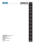
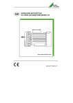
Audio VertriebsEntwicklungsgesellschaft mbH _____________________________________________________________________ Andante 16 Digital Mixer With 16 mic/line inputs and 8 outputs User Manual AVE GmbH . Gustav-Rau-Straße 6, . D-74321 Bietigheim-Bissingen, Telefon +49 7142 788790 . Fax +49 7142 7887918 E-mail: [email protected] homepage: www.ave-stuttgart.de Subject to technical changes Contents Table of contents Introduction Safety instructions Scope of delivery Explanation and description of the Andante 16 Section 1 (qualified personnel) Installing the software Programming the Andante 16 Section 2 (user) Operation of the Andante 16 in user mode Section 3 (Admin) Changes in settings Technical Specifications Notice 2 Introduction Thank you for choosing the 16-channel digital mixer “Andante 16” from AVE. No matter what your requirements are, due to its advanced technical design, it ensures trouble-free use with sound exposure in a variety of facilities such as churches, courtrooms, government offices, conference rooms, schools, universities, etc. The following statements and descriptions refer to the “Andante 16”, but are also applicable for the “Andante 8”, since only the number of inputs and outputs are different. The Andante 16 is equipped with its own software. This makes the programming via laptop or PC easily and conveniently. Safety Instructions LOCATED INSIDE THE UNIT ARE HAZARDOUS VOLTAGES. DO NOT REMOVE THE COVER. INTERNAL MODIFICATIONS OR SERVICE WORK SHOULD ONLY BE CONDUCTED BY QUALIFIED SERVICE PERSONNEL. The “Andante 16” comes with an approved power cable. At one end of this cable is a three-pronged AC power connector (IEC plug) and at the other end of a CE-standardcompliant Schuko-plug for connection to a 230 V / 50 Hz AC voltage source. Please ensure that this power supply cable is not damaged. Do not use defective or damaged power cables! Scope of delivery Please check immediately upon receipt the package integrity, the contents for completeness and proper delivery of the unit. The delivery scope of the unit includes: - The “Andante 16” - USB - stick - USB - cable - Operating instructions - Power supply cable Please keep the operating instructions in a safe place and make them available to qualified personnel for making necessary changes to the device. 3 Explanation and description of the „Andante 16” You should acquaint yourself with the different functions and optical circumstances of the device, bevor you start programming. 2 3 1 4 5 1 16 inputs – Each input has the same functions. 2 Matrix 3 8 outputs 4 Display 5 VOLUME/VALUE and PRESET/PARAMETER 6 USB-connection 7 Power supply 6 7 16 inputs Each input has the same functions. 2 .1 .2 2 .1 .1 2.1.2 Select button for each input. 2.1.1 LED-Display: Select, Input-on, CLIP, Signal-on 4 Matrix 2.2.1 2.2.2 2.2.1 Matrix-Select-buttons for assigning inputs to the outputs. 2.2.2 LED-Display for select (SEL) 8 outputs each output has the same functions. 2 .3 .2 2 .3 .1 2.3.1 Select-button for the particular output 2.3.2 LED-Display: Select, Output-on, CLIP, Signal-on 5 Back panel of the “Andante 16” 4 3 2 1 5 4 6 5 1 Inputs 1 – 16 2 CD / Aux 3 Outputs 1 - 8 4 Aux – Outputs 5 RSC 232 6 Power supply 6 This manual is divided into 3 sections: The first section is intended for qualified personnel, which adjusts the settings via PC or laptop and the programming of the parameters, the automatic, the Matrix and the delays, etc. The second section explains how the user can easily and comfortably change the overall volume and retrieve the presets (up to 20) directly on the “Andante 16” device without using the laptop or PC. The third section is also intended for qualified personnel and describes how to make settings directly on the device without using the laptop. 7 Section 1 THE FOLLOWING MODIFICATIONS ARE ONLY TO BE PERFORMED BY QUALIFIED TECHNICAL PERSONNEL! Das Parameter – Menu / Programming of the „Andante 16” The functions and settings that can be changed in the Parameter-Menu, should only be performed by qualified technical personnel. Installation of the software The first step is to install the included Software CD of the “Andante 16”, on your Laptop or PC. Installation of the program To install, connect the supplied USB flash drive to your computer. You will start the installation program by clicking on the appearing desktop folder and then clicking on setup.exe Then follow the installation instructions. In the illustrated ad, enter your user name, your organization name and the license number that was included. After installation is complete you will have the following shortcut on the desktop: 8 Restart your PC or your laptop, so the program can be executed properly. Use the supplied connector cable between your laptop and Andante 16. After starting the program this picture (1) will appear on your desktop: The following pictures (2-15) describe the process of programming. 1 2 4 3 a b 5 Specify the type of device and confirm by pressing ok. In the menu bar you find under “File”, “Setup”, “Tools” details for handling the program. 9 You can hide the programming fields by clicking this symbol. Input Levels Enter the name Input On/Off Phantom power GAIN - setting Fader level setting Input option for programmer to chanche the volume through the user (+and-) at every entrance directly at the device VU-Meters Clipping indicator RMS level - display Bar for Menue Tools Mixmonitoring Start Equalizers Highpass-filter on/off Parametric equalizer AutoMix (1) On/Off On/Off Reduction of the levell during microphone is activated Is activated (3 – 8of dB)) Adjustment priority AutoMix (2) Holding time 10 Compressors On/Off Noise Gates On/Off 11 Parametric equalizer: 5 parameters are available for each input. The settings can be copied to other inputs. Input Parametric Equalizer Open to copy settings When you click on Parametric EQ Ch 1 you will open 5 bands. By deselecting the tick mark the band will not be copied. Copy and close 12 Matrix: activation of input 1-16 to output 1-8 Crosspoints ON / OFF Level - settings 13 Output Levels name On/Off Level - settings Input option for programmers for changing the volume through USER (+ and -) at every outlet directly at the devise Delay settings VUMeters Clipping - settings Level – display when Mixmonitoring start is activated Equalizers Parametric Equalizer Graphic Equalizer Limiters ON/OFF 14 Compressors ON/OFF Noise Gates ON/OFF 15 Setting and copying of the parametric EQ output follows the same procedure as the parametric EQ input. Output Graphic EQ: Parametric Equalizer Settings 16 Graphic EQ: Copy (Copying of the 31 bands in the Graphic EQ follows the same procedure as with the parametric EQ). System Setup Select, which preset the devise should start Select the display of the VUMeter setting of the name for inputs/outputs switching OFF: Micro; ON: RCA Panel Protection On / Off Pin Protection ON/OFF choose the PIN Code Deleting the global settings Panel protection (User Mode): If Panel protection is turned on you can change the volume by pressing and turning the VOLUME button. To select a preset you press and turn the PRESET button Pin protection: To activate the pin on admin mode. 17 Pin code: Enter your own password (Admin Modus) Complete system reset: Attention: This function erases all previously stored settings and resets the device back to factory settings. Preset Setup * opens „copy“ (look downward ) *** MastervolumeEinstellung für USER Status (ON / OFF) Sending and storing on DSP Chose the number of open microphones Retrieve saved presets Deleting presetsettings** *) Preset name: Before you save a configuration to the Andante 16 (Store) You need to give a name to the preset to be saved 1 - 20 to be able to retrieve this preset with the retrieve function again. **) Preset reset: With this button, the respective preset setting is canceled. open „Copy“ Opens the choice of the Preset-settings that can be copied 18 Description of the function by using a touch-panel Selection oft the „Application Mode“ Application Mode: „Admin/User Modus“ Click at „User Mode Input/Output“ for the microphones/outputs , which should be operated at the touch-panel. OK: the following picture appears: „Preset Input Output“ selection example: Input With the Ctrl + T key you come back to „Application Mode“. 19 Section 2 Operation in "user mode" Note: The volume control in "user mode" is restricted in order to prevent operating errors. If the protection is activated, the volume is adjusted by pressing and turning the v/v button and to select a preset by pressing and turning the p/p button. Control of the entire volume By turning the v/v button the total volume will be increased or decreased (master volume). Select preset With the p/p button a desired preset is selected. Input level 1-16 Press the select (Sel) button and turn v/v key, to increase or to decrease the volume. Output level 1-8 Press the select (Sel) button and turn v/v key, to increase or to decrease the volume. Press the v/v button to return to the main menu. Section 3 Admin mode Please note that this mode must be executed by qualified personnel. Press and hold the p/p button and turn the power on until the following appears on the display: Admin Mode - Preset 1 With Preset 1 - 20 the following functions can be performed: Input 1: Press the Select button w/w button input on/off p/p input gain - w/w dB Level + p/p Volume Control - w/w dB Level + p/p phantom power w/w on/off p/p automix function w/w on/off p/p RMS VU meter-level input 1. To return to the main menu press the w/w button briefly. The same procedure applies for Input 2 – 16. The same procedure applies to Preset 2 – 20. Output 1-8 Press the Select button w/w button output on/off p/p button level - w/w dB level setting + p/p button RMS VU-meter level output. The same procedure applies to Output 2 – 8. To return to the main menu press the w/w button briefly. 20 Matrix Select button 1 or 2 You will see the following: Matrix Status Input 1 to Output 1 p/p button matrix level w/w button dB level setting + The same procedure applies for input 2 – 16 at output 1. The same procedure applies for input 1-16 at output 2 – 8. To return to the main menu press the w/w button briefly. Preset Setup By briefly pressing the p/p button you will be asked to enter a pin – a four digit number. Insert pin (default = 0000): • Turn the w/w button for letters, special characters and numbers. • If you press the p/p button briefly, the cursor jumps to the next position. After entering 4 numbers, press the p/p button to reach the next menu. This inscription appears on the display: Save Changes Exit Ok Turn the p/p button until Preset Setup appears on the display, press briefly to go to the menu. By pressing the button again Preset Selection appears. With w/w button Choose Preset occurs. Turn the p/p button for Preset Status - w/w button on/off Turn the p/p button for Master Volume - w/w for volume regulation + Turn the p/p button for number of open microphones - w/w choice of the number of open microphones. By turning the p/p button the following appears: Preset 1 Name (enter preset name) • Turn the w/w button for letters, special characters and numbers. • If you press the p/p button briefly, the cursor jumps to the next position. By turning the p/p button the following appears: Preset 1: In EQs Preset 1: Copy Turning of the w/w button: Selects which copy from Preset 1 (in EQs) to Preset 2-20 Briefly press the p/p button: copy starts. By turning the p/p button the following appears: Preset 1: Out EQs Preset 1: Copy Turn w/w button: Selects which copy from Preset 1 (Out EQs) to Preset 2-20 Briefly press the p/p button: copy starts. Turn p/p button Preset 1: Setup Preset 1: Copy Turn w/w button: Selects which copy from Preset 1 (Setup) to Preset 2-20 Briefly press the p/p button: copy starts. Turn p/p button Preset 1 Setup Reset Briefly press p/p button to delete the displayed preset Briefly press w/w button - turn p/p button (go back) Save Changes -> Exit OK Press w/w button: Exits the menu without saving Press p/p button 2 times: Save By turning the p/p button you leave the Preset Setup and enter System Setup Briefly press to enter the menu. Startup preset Turn w/w button: selection of presets, with which the device starts at switching on 21 Turn p/p button: main VU-meter Turn w/w button: selects the VU meter in the display input 1-16 or output 1-8 Turn p/p button: panel protection Turn w/w button: panel protection on/off in user mode Turn p /p button: PIN code request Turn w/w button: PIN code request on/off in admin mode Turn p/p button: PIN code change Press p/p: change PIN code Insert New Pin: Enter the new PIN and confirm (press p/p button) Turn p/p button: RCA Input 8 Enable (turn on input 8 to RCA - CD, cassette) Turn w/w button: on/off Turn p/p button: RCA Input 16 Enable (turn on input 16 to RCA - CD, cassette) Turn p/p button: welcome text (any entry) Procedure as text or numerical entry (see above) Turn p/p button: LCD contrast level Turn w/w button: sensitivity adjustment Turn p/p button: global settings - reset Press p/p button: confirmation No / Yes Attention: If you press yes, you will delete all previous settings and reset the unit back to factory condition! 22 Andante 16 – Technical Specifications Analog Input Section: Number of balanced inputs 14 + 2 (XLR type connector) Number of unbalanced inputs 2 Dynamic range 122 dB (“A” weighted) Analog gain (digitally adjustable) 0 dB ÷ 70 dB with 0.5 dB steps Nominal sensitivity (balanced input) -84 dBu (38,8 µVrms) Phantom power (digitally activated) +48 V stabilized, very low noise Balanced input impedance (XLR) 5,8 kΩ @ 1 kHz Unbalanced input impedance (RCA) 14,7 kΩ @ 1 kHz Frequency response (20 Hz ÷ 20 kHz @ +4dBu) -0.5 dB ÷ 0 dB Maximum balanced input level 20,2 dBu (7,92 Vrms) Input protections radio frequency interference (RFI) (RCA type connector) transient voltage spikes external overvoltage Analog Output Section: Number of balanced outputs 6 + 2 (XLR type connector) Number of unbalanced outputs 2 Dynamic range 121 dB (“A” weighted) Residual noise of output driver -101 dBu (20 Hz ÷ 20 kHz) Nominal level (balanced output) 4 dBu (1,23 Vrms) Maximum level (balanced output) 20.2 dBu (7,92 Vrms) Output impedance 50 Ω typical Output protections short circuits (RCA type connector) radio frequency interference (RFI) transient voltage spikes external overvoltage Analog to Digital Converter Bit resolution 24-bit Converter type sigma delta Sampling frequency (Fs) 48 kHz Signal to noise ratio (SNR) 111 dB (“A” weighted @ 48 kHz) Dynamic range 111 dB (-60 dBFS) Total harmonic distortion (THD) -102 dB (1 kHz, -0,1 dBFS) Oversampling factor 128 Fs 23 Digital Signal Processor DSP 32-bit / 40-bit, Floating-Point 400 MHz - 2,5 ns instruction cycle Super Harvard Architecture 2,4 GFLOPS, 2Mbits SRAM Digital to Analog Converter Bit resolution 24-bit Converter type sigma delta Sampling frequency (Fs) 48 kHz Signal to noise ratio (SNR) 117 dB (“A” weighted @ 48 kHz) Dynamic range 117 dB (-60 dBFS) Total harmonic distortion (THD) -104 dB (1 kHz, -0,1 dBFS) Delay time 0,66 ms Oversampling factor 256 Fs Digital Processing Inputs Blocks: Highpass filter (anti hum, anti rumble, ect) Butterworth filter type with cutting frequency at 160 Hz and slope12 dB/Octave 5-PEQs equalizer Noise gate Dynamic compressor range Frequency [20 Hz ÷ 20 kHz] Gain [-15 dB ÷ 15 dB] Bandwidth [0,014 ÷ 6,672 oct] Threshold [-60 dBFS ÷ 0 dBFS] Hold Time [100 ms ÷ 10 s] Threshold [-90 dBFS ÷ 20 dBFS] Ratio [R=1:1 ÷ R=20:1] Post Gain [-20 dB ÷ 20 dB] Attack Time [1 ms ÷ 250 ms] Release Time [10 ms ÷ 2500 ms] 24 Automix function Hold Time, [100 ms ÷ 5000 ms] Attenuation [-60 dB ÷ 0 dB] NOM Gain (increase post gain of -3 dB for each doubling of opened automix channels) Priority [1 (lowest) ÷ 5 (highest)] Max opened channels Fader level [1 ÷ 16] [-60 dB ÷ 10 dB] Input / Output Routing Matrix: Matrix size 16 In / 8 Out Matrix cross point level adjusting [-60 dB ÷ 10 dB] Output Blocks: 5-PEQs equalizer Frequency [20 Hz ÷ 20 kHz] Gain [-15 dB ÷ 15 dB] Bandwidth [0,014 ÷ 6,672 oct] 31-Bands graphic equalizer Gain [-12 dB ÷ 12 dB] Noise gate Threshold [-60 dBFS ÷ 0 dBFS] Hold Time [100 ms ÷ 10 s] Threshold [-90 dBFS ÷ 20 dBFS] Ratio [R=1:1 ÷ R=20:1] Post Gain [-20 dB ÷ 20 dB] Attack Time [1 ms ÷ 250 ms] Dynamic compressor range Release Time [10 ms ÷ 2500 ms] Limiter Threshold fixed at 0 dBFS Delay [0 m ÷ 233 m], [0 ms ÷ 679 ms] Phase control [0°, 180°] Output level [-60 dB ÷ 10 dB] Master level [-60 dB ÷ 10 dB] 25 Data Connections Front panel USB 2.0 Rear panel RS232 @ 38400 kbit/s Display LCD 20 characters x 2 lines PSU Module AC range 230 VAC ± 10% Input frequency 47 Hz to 67 Hz Power consumption max 33 W Analog voltages +48 VDC, ±15 VDC, +5 VDC Digital voltages +3.3 VDC, +1,2 VDC Voltage regulators linear type (no switching noise) Mechanical Height 88 mm Width 484 mm Depth 260 mm + 60 mm connector Weight 7 kg Temperature Range Indoor 0°C to 40°C (32°F to 102°F) Compliances AES48-2005 grounding scheme 2002/95/EC CE 26 Notice ALL AVE mbH DESIGN SPECIFICATIONS, FILES, DRAWINGS, TABLES, LISTS, AND OTHER DOCUMENTS ARE BEING PROVIDED “AS IS.” AVE mbH MAKES NO WARRANTIES, EXPRESSED, IMPLIED, STATUTORY, OR OTHERWISE WITH RESPECT TO THE MATERIALS, AND EXPRESSLY DISCLAIMS ALL IMPLIED WARRANTIES OF NONINFRINGEMENT, MERCHANTABILITY, AND FITNESS FOR A PARTICULAR PURPOSE. Information furnished is believed to be accurate and reliable. However, AVE mbH assumes no responsibility for the consequences of use of such information or for any infringement of patents or other rights of third parties that may result from its use. No license is granted by implication or otherwise under any patent or patent rights of AVE mbH. Specifications mentioned in this publication are subject to change without notice. This publication supersedes and replaces all information previously supplied. AVE mbH products are not authorized for use as critical components in life support devices or systems without express written approval of AVE mbH Corporation. Trademarks AVE mbH and the AVE logo are trademarks or registered trademarks of AVE mbH in the Germany and other countries. Other company and product names may be trademarks of the respective companies with which they are associated. Copyright © 2015 AVE mbH. All rights reserved. Consulting • Planning • Developing • Assembly of electroacoustic sound systems AVE GmbH • Gustav-Rau-Straße 6 • 74321 Bietigheim-Bissingen • Germany Phone +49 (0)7142 78879-0 • Fax +49 (0)7142 78879-18 [email protected] • www.ave-stuttgart.de 27