1
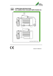
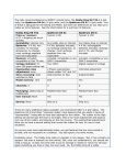
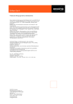
OPERATING INSTRUCTION
OIL-FREE VACUUM PUMP MODEL TD
9000-607-17GB/01.09
The information in this document can be
altered without prior announcement. No
part of these pages may be duplicated or
used, for any purpose, without prior written permission of the company, Dürr
Technik; either electronically or mechanically.
© 2007 by Dürr Technik
All rights reserved.
The use of brand name, trade name,
trademark etc. in this manual is covered
by trademark protection legislation and
must not be assumed to be free to use.
These operating instructions correspond
with the technical standard of our products, subject to alteration and errors accepted.
2
The present operating instructions give
you all the necessary advice for the proper
and safe handling of the oil-free vacuum
pumps model TD.
Please read and carefully observe the operating instructions to avoid mistakes and
dangerous situations.
The operating instructions are arranged as
follows:
Chapter
Planned purpose
Target group
Chapter 1
Gives you safety advice and important
general information for the products.
Installer, operator, qualified
personnel, user
Chapter 2
Contains detailed instructions and advice for the transport, storage, installation and the initial operation of the
product.
Operator, installer and qualified
personnel
Chapter 3
Contains instruction and advice for safe
technical handling of the product.
User
Chapter 4-5
Gives detailed instruction for cleaning,
maintenance and servicing the product.
Operator, qualified personnel
Appendix
In the appendix you will find important
technical information.
Qualified personnel
3
PREFACE
This operating manual is valid for oil-free
vacuum pumps, hereinafter called product.
The operating manual is only valid so long
as your product complies with the status
described within.
These instructions contain all details required for the transport, installation, operation, shut-down and maintenance of these
products.
Therefore please read the operating instructions carefully prior to the first operation, thus ensuring the safe and economic
application of the products.
When a fault occurs or maintenance is required which is not dealt with in the operating manual, you should contact our
qualified personnel.
All service and maintenance work must
be carried out by qualified personnel.
If service and maintenance work is neglected or carried out improperly, our warranty will be invalidated.
Should you have any problems understanding the operating instructions our
qualified personnel will be pleased to help
you.
Dürr Group
Dürr Technik GmbH + Co. KG
Pleidelsheimer Straße 30
74321 Bietigheim-Bissingen
Telefon 0 71 42 / 90 22 0
Telefax 0 71 42 / 90 22 99
4
CONTENT
1. INTRODUCTION AND GENERAL
ADVICE .................................................. 6
1.1
Symbol explanation and
definition.................................... 6
1.1.1 Symbol explanation ................... 6
1.1.2 Definitions ................................. 6
1.2
General safety advice................ 6
1.3
Product description.................... 8
1.3.1 Agreed application..................... 8
1.3.2 Function description..................... 8
1.3.3 Delivery schedule ...................... 9
2. Transport, storage ........................... 10
2.2
Transport and storage
requirements ........................... 10
2.3
Assembly and initial operation. 11
2.3.1 Environment requirements ...... 11
2.3.2 Vibration damping ................... 12
2.3.3 Assembly position ................... 12
2.3.4 Hose connections.................... 13
2.3.5 Electro installation ................... 14
2.3.6 Protection type ........................ 14
3. Operation : ....................................... 15
4. Cleaning ........................................... 15
5. Maintenance..................................... 15
5.1
Suction filter ............................ 15
6. Repair ............................................... 16
6.1
Dismantle ................................ 16
6.2
Checking slide vanes .............. 17
6.3
Assembly................................. 17
Appendix .............................................. 18
Appendix 1:Technical Data ................ 18
Performance diagramme.................... 19
Appendix 2:Dimensions ..................... 20
Appendix 3:Manufacturer Declaration 21
Appendix 4:Trouble Shooting............. 22
Appendix 5: Exploded diagramme ..... 24
Appendix 6: Spare parts list ............... 24
Appendix 8: Addresses ...................... 26
Index
................................................ 27
5
1. INTRODUCTION AND
GENERAL ADVICE
1.1
Symbol explanation and
definition
1.1.1 Symbol explanation
In the manual and on the product hand
symbols and pictograms are used whose
meaning you should memorise. These
symbols help you to understand the information in this manual quicker and make
you aware of potential danger or important
advice.
Attention! Danger sign. It points out
danger as well as rules and bans to
prevent personal and /or danger to
property.
Advice! Attention is brought to advise on the handling and economic
use of product.
Definitions
User, Operator: The responsible Person
who has the authorisation to use the
product. The user must have been given
instructions on the safe handling of the
unit from the appropriate authority.
Operator Authority: Responsible for the
safe installation, regular servicing and
cleaning of the product.
Qualified personnel: Trained by the operating authority or by authorised Dürr
Technik personnel who are aware of the
dangers of the product and familiar with
the technical aspects of the product.
Qualified personnel are trained to carry
out service and repair on the product.
Product: General term used for oil-free
vacuum pumps model TD.
1.2 General safety advice
Warning of hot surfaces! There
is a danger of burns! Observe especially that these surfaces may
still be hot after the product has
been switched off. Work near
these surfaces only after they
have cooled off.
During use, care and maintenance of the
product, the following fundamental safety
measures must be observed for the protection of the operator, maintenance and
service engineers as well as the product:
During the development and
manufacture of the product, the
recognised regulations of the
technical aspects, as well as the
recognised valid standards and guidelines were taken into account and used. In
addition the product has been de-signed
and constructed in such a way that endangerment through the agreed use are
minimized. Nonetheless we feel obliged to
describe the following safety measures so
the remaining dangers can also be minimized.
CE Conformity symbol. It can be
recognised by this conformity
symbol that the product corresponds to the safety guidelines of
the European Union.
Warning! When electrical equipment is being used, the basic safety
precautions must be followed, to
prevent risk of fire, electric shock
and personal injury.
Warning against electric energy!
Your life could be in danger. Make
sure that all electrical work is carried
out by a qualified electrician.
Warning advice. The product can
start without warning!
On the product and in the operating instruction special information signs and warning
Symbols with following meaning are used:
6
1.1.2
Therefore please read the manual
to hand, prior to starting work. Keep
this manual within reach for the engineer and the operator. The information should be passed on to any
successor.
During operation of the products the relevant laws and regulations for the place of
deployment must be observed! In the interest of safe operation the authorised operator and the supervisory personnel are
responsible for keeping within the regulations.
For all maintenance and repair work the
mains plug must be pulled out of the
socket.
Attention! Work on electrical equipment must only be carried out by a
qualified electrician.
Only original spare parts must be used.
Otherwise there may be injury to the user.
Warning! The use of other spare
parts and other accessories, as
stated in this manual, can cause
personal injury. Only use spare
parts permitted by the manufacture!
Check during all work on the product for
possible dangers. All parts must be correctly fitted and all requirements fulfilled to
ensure safe operation. Should the product
be damaged in any way, the product
should no longer be used. The product
should only be repaired by experts. Mark
the defect clearly and pull out the mains
plug, so that until the repair is effected, no
accidents or damage can occur through
the defective product.
Take account of environmental influences! Do not operate the product in a wet or damp environment.
In dangerous situations or during
technical problems, separate the
product at once from the power
supply (pull the plug).
Check regularly the power supply line and
the casings of electrical components and if
they are damaged, have them repaired by
a qualified electrician.
Check the electrical equipment for external damage before work starts. Check
thoroughly whether lines or cables are
damaged. If there is damage, do not operate the product.
If there is damage, do not operate
the product. Pull out mains plug!
7
1.3 Product description
1.3.1 Agreed application
The product is intended for aspiration of
air and non-aggressive gases.
The aspiration of fluids, aggressive or explosive gases is forbidden! It will cause danger to health
and the possible danger of explosion or fire!
The product is designed for use in equipment or a unit. It should only be used if the
manufacturer of the equipment or unit, in
which the product is to be incorporated,
has ensured that all requirements for safe
operation has been met.
The product is designed for operation in a
dry, well ventilated room.
The product should not be operated in a
damp or wet environment. In addition, operating near gases or flammable fluids is
forbidden.
1.3.2 Function description
The product belongs to the group of multivaned vacuum pumps. The product parts
are directly connected to an electro-motor.
The basic model is provided with a
230V/50 Hz electric-motor as standard.
With the electric-motor an additional temperature switch is integrated. When the
temperature switch is activated, the product switches off automatically.
Warning advice. After cooling off
the product starts automatically.
8
The product parts consist of a pump housing (5), a rotor with 5 slide vanes (2) a felt
washer (4) and a pump cover (1).
The cast iron rotor is situated off-centre in
a cylindrical chamber (5). In the rotor are 5
valve plates (2) movably arranged. During
rotation these are pushed against the wall
of the pump casing (5) by centrifugal
force, during which the volume between
the valve plates changes continuously.
The vacuum is created through volume
variation.
At unduly high temperatures the
product will switch itself off.
Product for pressure operation.
The product TD-801 with exhaust
nozzle can also be fitted as a compressor. The max. pressure is
approx. 0.8 bar. Exceeding this
pressure can lead to motor damage.
1.3.3
1
1
2
3
4
5
6
Pump cover
Slide vane
Suction nozzle
Felt washer
(not necessary for 1260-18 and
1260-22)
Pump housing
Electro motor
Delivery schedule
The product are also supplied as a ready
to use portable version. The basic version
is fitted onto a base plate with carrying
handle. Additionally in the motor connection box there is an ON/OFF switch and a
mains cable with fitted plug. The base
plate is fitted with 4 anti vibration dampers
for damping vibration.
9
2. TRANSPORT,
STORAGE
2.2 Transport and storage requirements
2.1
Temperature:
-25 °C to + 55 °C
Relative humidity: 10% to 90% (without
condensation)
The products are intended for immediate
use. Products in their original packaging
can be stored in a warm, dry, dust free
room. If the products should be stored
long term, e.g. as a replacement pump
then they must be protected with a drying
agent. This will prevent corrosion of the
inner parts of the product.
Transport and Storage
The product is dispatched from the factory
in a specially padded transport carton.
With this the product is safe against transit
damage. Always use the original packaging of the product if possible.
Transport the product in an upright position.
Protect the product during transport
and storage against dampness and
extreme temperatures. Take special
care that the electrical equipment
does not get damp or wet.
Product must only be transported
pressureless. Remove air from
any fitted pressure containers
and lines.
Keep packaging if at all possible.
Environmental rules regarding the disposal of the packaging must be observed
and to assist this please note the labels on
the packaging.
10
When the product has been stored for a
long time the motor ventilator must be rotated by hand and then started a number
of times.
The mains supply must be disconnected before rotating the
product by hand.
2.3 Assembly and initial operation
The product is designed to be inserted
into units. They should only be fitted by a
trained engineer, who is familiar with any
potential hazards. The product must only
be operated when it has been made certain that all relevant safety requirements
have been fulfilled.
50
40
2.3.1
Environment requirements
The product must only be installed
and operated in dry, well ventilated
and dust free rooms.
2
Take care when choosing the site for installation that the product is easily accessible for operating, cleaning and maintenance, especially the connection piece
and the operational parts.
The product should be installed on a level
and sufficiently solid surface. To reduce
vibration the supplied vibration dampers
should be mounted. If the vacuum is built
into a machine or housing, it must be
noted that the identification plate is visible
and readable, without having to dismantle
the product. Also ensure that the connection clamps are easily accessible when
taking off or opening the housing.
Please make sure that the exhaust airway is clear.
When fitting into a housing it should be
observed that the minimum distance is
kept (see fig. 2 and 3). It must also be
noted that there is sufficient ventilation. In
certain cases an independent ventilation
system may be required.
Please make sure that the power line connection and air hoses are not kinked.
3
11
The room temperature must not fall below
5° C, otherwise problem free operation
cannot be guaranteed.
The ambient operating temperature must
not exceed 40°C. Operating ambient temperatures above 40° C will require additional ventilation. The ideal ambient temperatures are between 10°C to 15°C.
Approx. 70% of the products induced electrical energy is converted
into heat and is given off to the surrounding area.
The motor ventilator normally ensures an
effective pressurised cooling of the product. To do this the air must be able to flow
to and for unhindered. Ventilation openings must be large enough to allow this to
happen. In unsuitable cases, e.g. when
the product is built-in an independent air
cooling system might be required.
2.3.2
Vibration damping
The product produces vibrations. To
dampen this vibration suitable vibration
dampers must be used.
Vibration dampers specially made for these products can be found in the accessory
list.
Do not use rigid connections between the
product and the pipeline system.
The wrong kind of vibration dampers or the use of rigid connections can damage the product or
the equipment into which the unit
has been built.
4
1 Suction nozzle
2 Exhaust nozzle / pressure nozzle
(only on special models
1260-18 and 1260-22)
12
2.3.3
Assembly position
Products must be fitted in a horizontal position (see fig. 2 and 3).
2.3.4
Hose connections
Product connections:
A non-return valve is necessary.
If when switching off the product
the evacuated space cannot be
ventilated. The negative pressure
will aspirate air from the product
into the line system.
A fine filter must be built-in otherwise dust particles can be aspirated.
When fitting the fine filter please
note the through flow direction
(arrow).
5
Suction filter with non-return valve
Fine filter with non-return valve hose
connection:
Pull off the protective cap from the vacuum, and if required, the exhaust nozzle.
Then push a vacuum hose (NW8) onto the
suction nozzle (1, ill.4).
On the standard product the exhaust air
escapes sound dampened, via the felt
washer between pump cover and pump
housing. If the exhaust air should be led
out of the built-in space, a product with
exhaust nozzle must be used.
13
2.3.5
Electro installation
Work on electrical equipment must
only be carried out by qualified electricians!
Product to be installed must be connected according to the following instructions:
Please observe implicitly the regulations of
the local power supplier. The connection
can only be carried out on a voltage supply with correctly installed protective conductor.
The power supply voltage and frequency
must comply with the details on the model
label. The motors are designed for ±10%
fluctuation. The capacitor is allowed to
vary ±10% from the rated capacity. Please
make sure no connection cable is placed
across the product. The hot surface of the
product could damage the insulation of the
cable.
The electrical connection can be seen on
the circuit diagram (ill. 6).
The portable product is supplied ready
for connection with an on/off switch and
mains lead.
The mains voltage and frequency must
comply with the details on the model label.
6
14
The motors are designed for ± 10% fluctuation. The capacitor is allowed to vary
±10% from the rated capacity.
Please note the rotational direction of the motor (motor ventilator should rotate in a clockwise
direction)
The motor can be additionally
protected with a safety fuse.
On uncontrolled operation the
motor has to be protected by an
overcurrent protective relay
against short-circuit.
The following fuses are recommended:
200-240 V, 50/60 Hz Fuse 4 A neutral
90-127 V, 50-60 Hz Fuse 5 A neutral
Because of the small difference between the starting and nominal current of small motors and the greater
tolerance of safety fuses, surges of
power are not easy to control. Only
a short circuit can be protected
against.
2.3.6
Protection type
The product must only be assembled or
used according to their protection type.
3. OPERATION:
Please note whether the product
has a hot surface. There is a danger of burns, if these surfaces are
touched when hot.
Before daily operation please check that
the suction filter is clean.
Product does not start against
pressure. Therefore the pressure
line must be pressure free. The starting volume should be ≥ 50 cm3.
Operate the product via a separate switch
or through the system, for the portable
product insert the mains plug and use the
on/off switch.
4. CLEANING
To maintain faultless function, it is recommended to keep the product clean.
The product has hot surfaces. Let
the product cool off before starting any cleaning work.
5. MAINTENANCE
The product has hot surfaces.
Let the product cool off before
starting any maintenance work.
The stated maintenance intervals are guidelines for normal operational conditions.
With extreme operational conditions (e.g.
long working times under full load, high
ambient temperatures, very dusty ambient
air, high humidity) the maintenance intervals must be shortened. When carrying
out maintenance work the mains plug
must be pulled out. Alternatively the product must be voltage free.
5.1 Suction filter
The maintenance interval of the suction filter depends on the dust content of the aspirated gases and the filter area. Working
without or with a macro pored suction filter, the product parts will deteriorate
quicker. The volume flow is noticeably reduced with dirty suction filters. Change dirty suction filters!
Clean the surfaces of the product with a
fluff free cloth, special attention particularly
the cooling fins and the motor ventilator
kept free from dust and pollutants.
Operating time
Activity
Measures to be taken
Daily
Sight check suction filter
Change dirty filter
Every 5000 h
Check rotor vanes
Dismantle rotor vanes and measure
15
6. REPAIR
6.1 Dismantle
See ill. 6 and 7.
Separate product from power
supply. Lines must be pressure
free.
All repair work must only be carried out by a qualified personnel.
7
1 Screw
2 Pump cover
3 Felt washer
(not for 1260-18 and 1260-22)
4 Rotor
5 Vane
6 Screw
7 Pump housing
8 Electro motor
1. Disconnect all hose lines.
2. Turn off all electrical connections and
dismantle product.
3. Undo screws (1) holding pump cover
(2) take off pump cover and remove felt
washer (3) and pull the slide vanes (5)
from the rotor.
4. Clean all component parts and blow
through with compressed air.
The pump housing and the rotor
must not be loosened from the
electric motor as they have been
factory set.
Before starting work with cleaning agents, eye protection,
breathing protection and relevant
protective clothing should be
worn.
No liquid and no lubrication must
get into the product!
All component parts should be given a visual inspection. Change any damaged
parts. Any parts which have to be returned
to the manufacture for repair should be carefully packaged and noted.
8
16
6.2
Checking slide vanes
Give the slide vanes a visual inspection.
Change slide vanes which are damaged
or very dirty.
Measure the slide vanes. If the height is
less than 13 mm, renew them. Always
change the complete set of slide vanes,
never an individual one!
6.3
Assembly
See ill. 7 and 8.
1. Assemble slide vanes as per ill. 8.
When fitting the pump cover take
care that the contact areas are
clean.
2. If necessary fit felt washer (3) and
pump cover (2) and fasten with screws
(1).
3. Re-assemble product.
4. Make electrical connection again and
connect hose lines.
17
APPENDIX
Pabs
End pressure
Sound level
Motor wattage
Current consumption
Motor
voltage
Frequency
weight
Protection
class
l/
min
mbar
dB(A)
P1
(W)
A
min
V
Hz
kg
IP
TD-461
1260-17 2,8
46
180
<54
200
230
1,5
1,0
1420
1700
220-240
50
60
9,1
54
TD-461
1260-18 2,8
46
180
<54
200
230
1,5
1,0
1420
1700
230
50
60
9,4
54
TD-461
1260-19
2,8
3,4
46
55
180
<54
140-170
160-180
2,1
1,8
1400
1700
90-115
50
60
9,4
54
TD-461T* 1260-32 2,8
46
180
<54
200
230
1,5
1,0
1420
1700
220-240
50
60
10,5
54
TD-800-14 1260-14 5,7
96
130
<60
360
370
3,3
3300
110
115
60
8
54
TD-801** 1260-21 4,8
80
130
<60
310-350
350
300
350
1,8-2,3
1,7
1,6
1,8
2850
3400
2800
3260
220-240
220-240
200
200
50
60
50
60
10
54
TD-801** 1260-22 4,8
80
130
<60
300
350
310-350
350
1,6
1,8
1,8-2,3
1,7
2800
3260
2850
3400
200
200
220-240
220-240
50
60
50
60
10
54
TD-801
1260-23 4,8
80
130
<60
300
400
3,0
3,5
2850
3400
100-115
100-127
50
60
9,4
54
TD-801*
1260-36 4,8
80
130
<60
310-350
350
1,8-2,3
1,7
2850
3400
220-240
50
60
11,4
54
•
•
Art.-No.
m³/
h
Type
Suction capacity
Nominal data of motors
Suction capacity
S
Technical Data
S
Appendix 1:
-1
All motors are fitted with a temperature switch.
All models duty rated S1 = 100% duty rated.
*T = portable products
** can be applied up to max. 800 mbar overpressure (special model with exhaust air nozzle)
Remark: the sound-pressure level is higher on products with open exhaust air nozzles
18
As our products are constantly being updated, they can be at variance with the
listed technical data. Should you use this Operating Manual for outline planning,
please clarify with us the current technical data of the product required.
Performance diagramme
Time necessary to pump out a 10 l volume
1000
example for another volume
connected volume: 30 l
requested endpressure:
200 mbar
selected pump:
TD 461
TD 801
Receiver pressure [mbar]
500
TD 461
pump running time: 30 / 10 * 60 = 180
example
200
180
130
100
1
10
60
100
pump running time [s]
19
Appendix 2:
Dimensions
Portable model
Built-in model
Type
TD-461
TD-461
TD-461
TD-461 T
TD-800-14
TD-801
TD-801
TD-801
TD-801 T
20
Art. – No.
1260-17
1260-18
1260-19
1260-32
1260-14
1260-21
1260-22
1260-23
1260-36
l
256
256
258
265
250
256
256
258
265
b
157
157
166
170
158
157
157
166
170
h
147
147
165
228
158
147
147
165
228
Appendix 3
Manufacturer Declaration
MANUFACTURER’S CERTIFICATE FOR MACHINES
98 / 37 EEC annex II, B
Manufacturer:
Dürr Technik GmbH & Co. KG
Adresse:
Pleidelsheimer Str.30
D-74321 Bietigheim- Bissingen
Reference number:
Type TD
Product name:
Vacuum pump
starting with serial number:
V 000001
Herewith we declare that prior to initial operation, it must be determined that the machine in
which this machine is to be installed, conforms to the stipulations of the applicable machine
directive, 98/37/EEC.
Directive for low voltage 73/23/EEC.
Directive electromagnetic compatibility EMC, 89/336/EEC.
Following harmonized standards are applied:
EN 1012-1:1996-07
EN 1012-2:1996-07
EN 60335-1:2007-02
EN 50106:2001-08
EN 60034-1:2005-04
EN 60034-5:2001-12
EN 55014-1,2:2002-08
Bietigheim- Bissingen, date 24.04.07
ppa. A.Ripsam
vice president Dürr Technik
Signatures registered with original document Dürr Technik archive
21
Appendix 4
Trouble Shooting
The following description for trouble shooting is only meant for qualified
personnel. Repairs must only be carried out by qualified personnel!
Fault
Possible cause
• Power supply missing
•
•
•
•
•
Product
does not
start
•
•
•
•
•
•
•
Performance falling off
•
•
•
•
22
Remedy
• Check mains and equipment fuse, if
necessary, call electrician
Power supply too low
• Check mains supply
Condenser defective
• Check condenser, if necessary, change it
Machine incorrectly connected • Check connections
Motor defective
• Factory repair
Protector in motor has switched • Let product cool-off
off
Warning: Product switches on again
automatically!
1. High ambient temperature
1. Arrange better cooling
2. Mech. sluggish
2. Factory repair
3. Protector defective
3. Factory repair
Suction filter blocked
• Insert new filter (see chapter 6.1)
Mechanically sluggish
• Factory repair
1. Dirt aspirated
1. Factory repair – in future fit in-line filter
Pressure in line
• Ventilate vacuum line
Motor ventilator blocked
• Fit ventilator cover correctly
Pump motor blocked, ice form- • Warm up pump above 5° C
ing from condensed water
pump
Lines leaking
• Check and if necessary renew
Suction filter very dirty
• Change suction filter, possibly fit filter
with larger surface area
Rotor vane worn
• Change rotor vane
Felt washer dirty
• Change felt washer
Rotor vane incorrectly inserted • Insert rotor vane correctly (see fig. 8)
during maintenance
Pump wrongly connected
• Check electrical connection (see fig. 6)
Fault
Possible cause
Remedy
• Factory repair
• Use suitable vibration absorbers
Product
too noisy
• Bearing damaged
• Vibration transmission to product
• Dirt in product
• Felt washer forgotten after
maintenance
• Rotor vane worn
• Rotation direction incorrect
• During maintenance not all rotor vanes have been inserted
Product
too noisy • Pump cover not fastened seand no
curely
output
• Soling of surface between
pump cover and pump casing
• Rotor vane sticking – fluid or
dirt aspi-rated
• Clean product; fit in-line suction filter
• Fit felt washer
• Change rotor vane
• Check electrical connection
• Fit missing rotor vanes (see fig. 8)
• Secure all screws
• Clean all surfaces
• Clean product and if necessary fit new
rotor vane only air non-aggressive gases
23
Appendix 5: Exploded diagramme
Appendix 6: Spare parts list
Pos
No.
Article description
TD-461
1260-17/-19
TD-461
1260-18
TD-461 T
1260-32
TD-800-14
1260-14
3
Felt washer
1260-100-08
—
1260-100-08
1260-100-08
5
vane
5x
1260-100-02
5x
1260-100-02
5x
1260-100-02
5x
1260-100-02
9
Filter with non-return
valve (3-er Set)
1100-040-00
1100-040-00
1100-040-00
1100-040-00
Further spare parts on request.
Accessories on request or by www.duerr-technik.com
24
TD-801
1260-21
TD-801
1260-22
TD-801
1260-23
TD-801 T
1260-36
1260-100-08
—
1260-100-08
1260-100-08
5x
1260-100-02
5x
1260-100-02
5x
1260-100-02
5x
1260-100-02
1100-040-00
1100-040-00
1100-040-00
1100-040-00
25
Appendix 7: Addresses
Technical advice
Dürr Technik GmbH + Co. KG
Postfach 1129
74301 Bietigheim-Bissingen
Telephone 0 71 42 / 90 22 - 0
Fax
0 71 42 / 90 22 – 99
www.duerr-technik.de
Dürr Technik (UK) Ltd.
Unit 5 Ashmead Business centre
Ashmead Road
Keynsham
Bistrol
BS31-1SX
Telephone 0117 9860414
Fax
0117 9860416
[email protected]
Dürr Technik Sverige AB
Box 302
S-571 24 Nässjov
Telephone 0380 - 55 49 80
Fax
0380 - 743 15
Spare parts service
Spare part orders to be sent in accordance with the existing spare parts list,
written to the above address or by telephone to the following number:
Telephone 0 71 42 / 9022 - 19
Fax
0 71 42 / 9022 - 99
[email protected]
For ordering spare parts the following
details are required:
•
Model no. and article no.
•
Order no. as per parts list
•
How many of each item required
•
Exact address to dispatch to
•
Dispatch details
26
Repairs / return delivery
When returning products, if possible, use
the original packing. Always pack the
equipment in synthetic packaging material.
If possible use recyclable packing material.
INDEX
A
Addresses............................................ 26
Advice.................................................... 6
Agreed application................................. 8
Assembly ............................................. 17
Assembly and initial operation ............. 11
Attention ................................................ 6
Authority ................................................ 6
C
Checking slide vanes........................... 17
Cleaning .............................................. 15
D
definition ................................................ 6
Definitions.............................................. 6
Delivery schedule .................................. 9
Dimensions.......................................... 20
Dismantle............................................. 16
E
Electro installation ............................... 14
Environment requirements................... 11
Exploded diagramme........................... 24
F
Fine filter.............................................. 13
Function description................................. 8
G
General safety advice............................ 6
H
Hose connections ................................ 13
M
Maintenance ........................................ 15
Manufacturer Declaration .................... 21
N
non-return valve ...................................13
O
Operation .............................................15
Operator .................................................6
P
Performance diagramme......................19
PREFACE ..............................................4
Product...................................................6
Product connections.............................13
Product description.................................8
Protection type .....................................14
Q
Qualified personnel ................................6
R
Repair...................................................16
Repairs.................................................26
return delivery ......................................26
S
Spare parts service ..............................26
storage .................................................10
storage requirements ...........................10
Suction filter .........................................15
Symbol explanation ................................6
T
Technical Data .....................................18
Transport..............................................10
Trouble Shooting ..................................22
U
User........................................................6
27
Dürr Technik GmbH + Co. KG
Postfach 1129 • 74301 Bietigheim-Bissingen
Pleidelsheimer Straße 30 • 74321 Bietigheim-Bissingen
Tel. (+49) 71 42/90 22-0 • Fax (+49) 71 42/90 22-99
Internet: www.duerr-technik.com
E-Mail: [email protected]
DÜRR TECHNIK Sverige AB
Box 302 • S-571 24 Nässjô
Tel.: (+46) 3 80 / 55 49 80 • Fax: (+46) 3 80 / 7 43 15
eMail: [email protected]
DÜRR TECHNIK (UK) Ltd
Ashmead Road, Keynsham • UK-Bristol
Tel.: (+44) 117/9 86 04 14 • Fax:(+44) 117/9 86 04 16
eMail: [email protected]
DÜRR TECHNIK France S.A.R.L.
26, rue Diderot • F-92000 NANTERRE
Tel.: (+33) 1 55/69 11 80 • Fax:(+33) 117/69 11 81
eMail: [email protected]