1
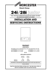
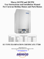
Morco 24CPM and 30CPM
User Instructions and Installation Manual
For Caravan Holiday Homes and Park Homes
Domestic Hot water
Output
Central Heating Output
Model
Gas Type
Morco 24CPM
LPG
26kW
24kW
Morco 30CPM
LPG
31kW
30kW
Morco 24CPM
Nat Gas
26kW
24kW
Morco 30CPM
Nat Gas
31kW
30kW
EC-TYPE EXAMINATION CERTIFICATE 177208
MORCO PRODUCTS LTD
Morco House, Riverview Road, Beverley, East Yorkshire, HU17 OLD
Tel: 01482 325456 Fax: 01482 212869
www.morcoproducts.co.uk
........~
....--....
. - .~.....-....~......-......-....
. - . ..__
.._
--~-
~~--
.~
~
HEATING & HOT WATER
'-..____/
1. USER INSTRUCTIONS
GAS SAFETY (INSTALLATION AND USE) REGULATIONS 1998 (AS AMENDED)
It is the law that all gas appliances are installed by a registered person, in
accordance with the above regulations. Failure to install appliances correctly could
lead to prosecution. It is in your own interest, and that of safety, to ensure that the
law is complied with.
Read these instructions carefully before attempting to operate the appliance.
Comply with all applicable warnings. Do not interfere with any sealed components,
and use the appliance only in accordance with these instructions.
This manual should be left with the owner of the boiler.
1.1 Introduction
The Marco 24CPM and 30CPM condensing combination boilers are wall hung,
room sealed, fan assisted, microprocessor controlled, fully modulating boilers
capable of supplying both central heating (CH) and instantaneous hot water (DHW).
The boiler can be set to work in a number of ways:
• DHW supply only
• CH supply only
• Both CH and DHW supply
The temperature of the CH and DHW supply can be set by using the knobs on the
control panel.
DHW Comfort Mode
The boiler has a "Comfort Mode" for hot water delivery only, that can be selected on
the front panel. In this mode the boiler "learns" your hot water requirements and "preheats" water prior to use to ensure faster delivery. With this mode switched on the
boiler will fire periodically even when no hot tap is opened- this is normal operation.
With this mode switched off the boiler will only fire for hot water delivery when a tap is
opened. This is called "economy mode"
LCD Display
Depending on the boiler status and user interaction with buttons and dials on the
control panel the following can be displayed on the LCD panel:
• Temperatures of water in the CH circuit- both actual and target
• Temperature of DHW- target only
• Fault Codes- in the event of a problem
• Pressure in the CH circuit
3
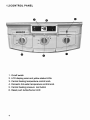
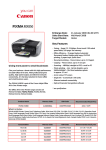
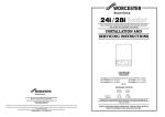
1.2 CONTROL PANEL
1. On/off switch
2. LCD display panel and yellow status LEOs
3. Central heating temperature control knob
4. Domestic hot water temperature control knob
5. Central heating pressure test button
6. Reset push button/burner LED
4
1. On/off switch
This knob is used to turn the boiler on and off- it will NOT reset the
boiler after a fault code has been displayed
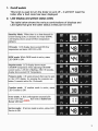
2. LCD display and yellow status LEOs
The table below shows the various combinations of displays and
LED lights that give the boiler status at that point in time
Stand-by Mode: When there is no heat demand for
central heating (CH) or domestic hot water (DHW).
LCD display shows actual CH flow temperature
(default).
CH mode: LCD display shows actual CH flow
temperature and status LED CH is ON.
DHW mode: While DHW mode is active, status
LED DHW is ON.
Setpoint mode: LCD display shows target
CRJDHW temperature when adjusting CHIDHW
control knobs . Left dot is flashing. After I 0 seconds,
display shows actual CH Temperature.
Pressure mode: CH water pressure (bar) can be seen
on the LCD display by pressing the pressure testbutton. It remains active for I 0 seconds.
Comfort mode: If comfort mode is active, status
LED Comfort is ON.
Error mode: A fault code appears automatically
on the LCD display. The fault code is flashed and
Burner LED turns
D.
Service mode: If service mode is active, status LED
Service is ON.
llr •
•
&=i
e
fit
~
IU
~
[IJf
ffi
gr)
m
•
•m
•
•
8
a
fJ
1
•
..
•
or •
at
~
G
•
•
lit •
tfM
E
I•
tFa
~
•
•
e
•
•
•
• •
m
8
0
C04iiFOFU
~
COiiiFcmf
~
COMfORT
~
COMFORT
~
CmlFORT
~
COJd1F0.'1T
~
•
COMFORT
e
~
~~r:~·
0
roMFORT
m!l
_
e
~
Bl
5
3. CH temperature control knob
This has 3 functions:
1. Set the CH target temperature between 30 deg C and 80 deg C
2. Select heating mode ON or OFF
3. The service mode is set by turning the knob fully clockwise- this
is only for use by engineers
.----Heating OFF
Service
Mode
,--------+---Heating ON
MIN
MAX.
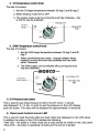
4. DHW Temperature control knob
This has 3 functions:
1. Set the DHW target temperature between 35 deg C and 60
deg C
2. Select comfort/economy mode - change between these
modes by turning the knob fully clockwise and then back
within 3 seconds.
3. The DHW supply can be switched off by turning the knob
fully anti-clockwise.
..
--...-..-.~...-..
=--===:;;= -· ==-
···~--
~
----t--Hot Water OFF
Comfort/ECO
Mode Selection
COMFORT
'------------.-- Hot Water ON
MIN
'
5. CH Pressure test button
This is used to see what pressure is held in the CH circuit - it should
read between1.0 -1.4 bar. In order to see the pressure on the LCD display,
push the button. The value will be displayed for approximately 10 seconds.
6. Reset push button/ burner LED
This is used to reset the boiler after any fault codes are displayed on the LCD panel.
In addition the colour of the LED indicates the following:
• Red LED - the boiler is in fault mode and a code should be visible on the LCD panel
• Blue LED- the boiler is operating normally and the burner is ignited
6
1.3 GENERAL GUIDANCE ON HOT WATER DELIVERY
The temperature of the hot water is governed by both the ambient temperature
of the cold water supply and its flow rate through the boiler. In the case of the
24CPM model at a flow rate of 10.6L/min there will be a maximum rise of 35°C
above ambient. At a flow rate of 6.8L/min there will be a rise of sooc above
ambient, (the slower the flow rate, the greater the temperature rise).
The flow rate of the hot water is controlled by the hot outlet tap, until the max flow
allowed by the boiler is achieved.
The temperature selector knob on the boiler is effective only when there is either
a low water flow rate or a high ambient water temperature.
- The boiler can theoretically supply more than one outlet simultaneously
However in practice the tap which is nearest will receive the most hot water. If
the shower is in use and a kitchen tap is opened virtually all the hot water will be
diverted to the kitchen as it offers the least resistance.
- If an outlet is too restrictive it will slow down the flow rate and increase the
temperature. For example, ensure the shower head is free from blockages
caused by scale.
- If a tap or shower head is too restrictive due to a fault or blockage, the flow rate
will be reduced to below the rate at which the boiler is able to operate, resulting
in a wide swing in temperatures. Either fix the restriction or turn the temperature
selector on the boiler down.
A
eaution:The boiler can produce water at over 1o·c when in central
heating mode. If you run a hot tap when the boiler has been heating the
radiators, the initial flow through the hot tap could be very hot. DO NOT
PLACE YOUR HANDS under the tap or use the shower until this initial flow
has passed.
-Allow time (30 seconds) for the temperature to stabilise after making an
adjustment at the tap before making further adjustments.
7
1.4 GENERAL ADVICE
ANTI PUMP SEIZURE DEVICE
When central heating is not being used, but the boiler is in the summer setting (for
domestic hot water only) the pump will automatically run for 30 seconds every 23
hours to prevent it seiz1ng. If the appliance has been shut down with the electrical
supply switched off for a period, this device will not work. The pump may be found to
have jammed when the appliance is switched back on. If so, consult your installer or
Gas Safe Registered Eng1neer.
NOTE: Seized pumps are not covered under warranty.
ROUTINE SERVICING
To ensure continued safe and efficient operation of the appliance it is recommended
that it is checked and serviced as necessary at re_gular intervals. The frequency of
servicing will depend upon the particular installation conditions and usage but in
general once a year should be regarded as a minimum even if only occasional usage
nas occurred.
It is the law that any service work MUST be carried out by a competent Gas Safe
Registered Engineer.
SAFETY
It is essential that these instructions are strictly followed for the safe and economical
operation of this appliance. The appliance is a fan-assisted room sealed gas boiler and
therefore the flue terminal MUST NOT BE OBSTRUCTED under any circumstances. If
it is damaged, turn off the appliance and consult your installer, or service engineer. If it
is known or suspected that a fault exists on the appliance it MUST NOT be used until
the fault has been rectified by a competent Gas Safe Registered Engineer.
THERMOSTATS/TIMERS/PROGRAMMERS
This appliance may be fitted with one of the above devices to control the central heating
function in the home. These devices may override the controls of the boiler. For
example: the boiler will not fire in CH mode when a room thermostat senses its set point
temperature has been reached or a time clock is outside of the time zone selected for
CH to operate.
If the boiler is installed in a Caravan Holiday Home, refer to the user manual for the
home, for the positions of all drain plugs.
Note: There are no drain plugs fitted to the actual boiler.
-Leave all taps and plugs open until the boiler is next needed for service. This will allow
any residual water to continue to drain.
NOTES ON FROST PROTECTION
The heating circuit and radiators should contain the correct level of antifreeze to
prevent damage during freezing conditions and should not be drained down.
Opening the hot and cold water drain cocks should be sufficient to drain all the
water from the boiler.
However in some installations it rna}! be necessary to blow through the system with
air to ensure the water has drained. The filling loop valve below the boiler may also
be used as an extra drain point.
ALL FROST DAMAGE IS OUTSIDE OF THE WARRANTY
8
2. GENERAL SPECIFICATION
The Marco 24-CPM and 30-CPM are a range of high efficiency condensing combination
boilers that use premix technology and achieve a grade A rating in SAP 2009. They are
designed to provide both Domestic Hot Water (DHW) and Central Heating (CH), although
the CH does not operate while the DHW is being used. The boilers are designed to be
wall hung and are room sealed, that is they obtain the air for combustion from outside
the dwelling and a fan returns the products of combustion to the outside. The range is
particularly suited to use in Caravan Holiday Homes and Park Homes. The boilers can
be supplied ready to run on either LPG or Natural Gas.
Both horizontal and vertical flues can be used and various elbows can be used to
accommodate a more complex route between the boiler and the outside of the dwelling.
The main printed circuit board provides all the functionality and safety features for
the boiler.
The board operates the gas valve, fan, pump,3-way valve and flame supervision.
The safety systems built into your appliance provide entire safety for you and your
appliance. The safety systems are:
>
>
>
>
>
>
>
>
>
>
>
>
>
>
>
>
Flue Gas Over-heat Safety System (105 °C)
Flame Failure Supervision
Boiler Over-heat Safety thermostat 2 levels: 95 °C and 105 °C)
DHW (Domestic Hot Water) Over-heat thermostat
CH Over Pressure Protection (3 bar)
CH Low Water Pressure Protection (0,8 bar)
High Voltage Protection System (260 VAC)
Low Voltage Protection System (160 VAC)
EMC (Electromagnetic Compatibility) Filter
Thermal Accumulation Protection (with by-pass circuit and "pump over-run")
Water Flow Supervision
Pump Run Protection (0,4 bar)
Pump Anti-sticking Function
3 Way Valve Anti-sticking Function
Automatic Air Vent
Expansion Vessel (7 litres)
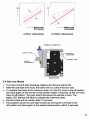
9
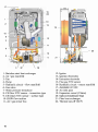
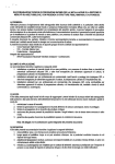
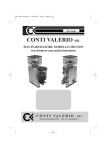
1- Stainless steel heat exchanger
2- Air I gas manifold
3- Fan
4- Pump
5- Hydraulic circuit- flow manifold
6- Gas valve
7- Water pressure transducer
8- CH tlo\v NTC sensor- immersion type
9- CH return NTC sensor - surface type
10- DHW tlow turbine
11- Air I gas mixer box
10
12- Igniter
13- Ignition electrodes
14- Ionization electrode
15- Flue gas NTC sensor
16- Hydraulic circuit- return manifold
17- Automatic air vent
18- Air inlet pipe
19- Expansion vessel ( 7 litres)
20- Siphon (Condensate Trap)
21- Plate heat exchanger
22- Thermal cut-off 160 °C
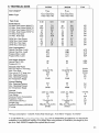
3- TECHNICAL DATA
24CPM
Gas Category*
Boiler Type
Type of gas
II
II
2H3i>
CrJ<~J· Ci*l• C4:3<¥lt
C.s:JW, C,)(:(,)t Cal(xJ
Unit
JOCPM
c IJCxh
21m
C:Jl!.liol• c4l(X)•
Cnt«>t C'i<xl> Ct~(~
G 20
G 31
G20
031
Performances
CH Min. Heat Output (80160 °C)
CH Max. Heat Output (80160 °C)
CH Min. Heat Output (50/30 °C)
CH Max. Heat Output (50130 °C)
CH Min. Heat Input
CH Max. Heat Input
6,6
22.2
7,3
24
6,8
22,8
7,9
22,2
8,8
24
8,2
8, I
27,3
22,8
30
8,4
28
9,6
27,3
10,8
30
10
28
kW
kW
kW
kW
kW
kW
DHW Min. Heat Output
DHW Max. Heat Output
DHW Min. Heat lnput
DHW Max. Heat Input
6,7
26
6,8
27
8
26
8,2
27
8,2
31
8,4
32
9,7
31
10
32
kW
kW
kW
kW
Gas Consumption**
Natural Gas (Max. Load)
Natural Gas (Min. Load)
Propane (Max. Load)
Propane (Min. Load)
Gas Supply Pressure
Natural Gas (G 20)
Propane (G 31)
Domestic Hot Water
Min. Flow Rate For Activating
Max. Flow Rate
Flow rate at 35 °C temp. rise
Min. Operating Pressure
Max. Operating Pressure
Set Temperature Range
Central Heating
Min. Operating Pressure
Max. Operating Pressure
Set Temperature Range
General
Electrical Supply
Fuse Rating
Electrical Power Consumption
Expansion Vessel
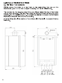
Dimensions (HxWxL)
Weight (Net)
Seasonal Efficiency (SEDBUK)
IP rating
9
2,38
0,71
1,77
0,64
2,92
0,88
2,17
0,77
m 3lh
20
37
20
37
mbar
mbar
3
12 (~t=JI
10,6
0,2
7
35-60
m3/h
kglh
kglh
3
•c)
14
(~t=32
.,C)
12,7
0,2
7
Jtr/min
Itrim in
ltr/min
bar
bar
35-60
oc
bar
bar
30-80
0,8
3
30-80
230V AC- 50Hz
4A
115
230V AC- 50Hz
4A
115
VAC/Hz
0,8
3
I
7
7
775 x454x3 70
775 x454x3 70
40
40,5
90,0-NG I 91,3-LPG
IPX40
90,1-NG I 91,6-LPG
IPX40
oc
A
watt
ltr
mm
kg
%
**For gas consumption- Calorific Value (Net) Natural gas: 34.52 MJim 3 Propane: 78.5 MJim 3
}> c type boilers (Crl(XJ, c33(s), c43{xh CsJ(x), c63(x), C8J(x)) are air independent gas appliances. Air required for
combustion is provided from outside via air supp!yducts with products of combustion, discharged by flue
gas ducts. Only M ORC O supplied flue options may be used.
11
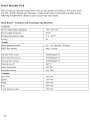
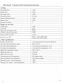
MAIN BOARD PCB
Main board has different parameters such as fan speeds according to the boiler types
(24 kW, 30 kW, Natural gas, Propane,). A main board can be converted to another type by
installing an appropriate (Boiler Control Card) to the main board.
Main Board - Technical and Functional Specifications
General
Power supply range (standard):
195-253 VAC
!Power supply frequency:
50Hz
Working temperature range:
0 oc- 60
Fusing:
4A
oc
Inputs
Water pressure switch:
0,5 - 2,5 V de (0,0 - 4,0 bar)
DHW flow turbine
Max. 14 1/min
CH flow NTC sensor:
10 k0hm@25 °C
CH return NTC sensor:
10 k0hm@25 °C
Flue gas NTC sensor:
10 k0hm@25
Thermal cut-off:
160 oc
Room thermostat:
24VDC
Ionization current:
min. 11-lA
Outputs
Gas valve:
230 VAC
Igniter:
230 VAC
Pump:
230 VAC
Fan:
230 VAC
3 way electrical valve
230 VAC
12
oc
30 sec
3 MIN
13
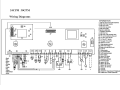
24CPM 30CPM
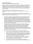
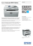
Wiring Diagrams
INFORMATION
I In
I
clgD
031
D
D
rn1
30
'A
32
I
I
X10
II
liiiil
II
27
[Q] B2s
26
33
23
@)
22
21
@)
~
X2B
I
X2A
I
I
-Brown
4
-Grey
18
-Yellow
- YellowGreen
-White
I
20
~
XlB I XlA
14 CUI-off 160"C
15 Flue gas NTC sensor
16 PWM Fan control
17 Water pressure sensor
18 DHW Flow turbine
19 Boiler chip card (BCC) port
20 Fuse4A
21 Power switch
22 CH potentiometer
23
24
25
26
27
-Blue
-Orange
-Pink
- Purple
-Red
XlC
PENLPENL
- Black
I
24
1 230 VAC Room thermostat (Optional)
2 230 VAC Power supply
3 230 VAC Pump
4 230 VAC Gas valve
5 230 VAC Igniter
6 Ignition electrodes
7 Ionization electrode
8 230VAC Fan
9 230 VAC 3 way divertar valve
10 PC communication/ e-Bus port
12 CH ratum NTC sensor
13 CH flow NTC sensor
28
29
30
31
~~~====:::::::::=.~
32
33
34
35
36
DHW potentlonmeter
Reset button
Flame LED (blue)
Error LED (red)
Connector MICS20
Pressure button
Status LED CH
Status LED DHW
Status LED Comfort
Status LED Service
LCD2x7
Terminal
24VDC RT /Opentherm RT(Optlonal)
Outside temp. sensor (Optional)
.q-
.-
4. GENERAL INSTALLATION
FOR THE USER
This appliance must be installed, adjusted or adapted for use with another type
of gas, only by a qualified and competent person.
A correct installation will ensure that your boiler works properly.
GAS SAFETY (INSTALLATION AND USE) REGULATIONS 1998 (As
amended).
It is the law that all gas appliances must be installed by a registered person, in
accordance with the above regulations.
Failure to install appliances correctly may lead to prosecution.
It is in your own interest, and that of safety, to ensure that the law is complied
with.
In addition to the above regulations, this appliance must be installed in accordance
with the current:
• lEE Wiring regulations,
• Heath and Safety Document No 635 'The Electricity at Work Regulations.
It should also be in accordance with the relevant recommendations in the current
editions of all relevant National Standards. Your particular attention is drawn to the
following standards relevant to an installation in Caravan Holiday Homes:
• BS 5482 part 2 Installations in caravans and non permanent dwellings.
• BSEN721 Leisure accommodation vehicles ventilation requirements.
• BSEN 1949 Installation of LPG System for Habitational Purposes in Leisure
Accommodation Vehicles.
For Park Home installation refer to:
• BS3632 Specifications for Residential Park Homes
• BS5440 Flueing and Ventilation
IMPORTANT: Manufactures instructions must NOT be taken in any way as
over-riding statutory regulations.
4.1 BOILER LOCATION
In positioning the boiler, the following limitations MUST be observed:
•
•
•
•
•
The position must allow for a suitable flue termination to be made.
The combination boiler must be installed on a flat vertical wall capable of
supporting its weight.
If the boiler is in a room containing a bath or shower, the boiler controls and
power supply must be so situated that they can not be touched by the person
using the bath or shower. Attention is drawn to the current lEE Wiring
Regulations, and in Scotland the electrical provisions of the Building
Regulations applicable in Scotland. (See 4.8).
A compartment used to enclose the appliance MUST be designed and
constructed specifically for the purpose. An existing cupboard, or compartment,
may be used provided it is modified accordingly.
Minimum clearance as stated in the technical data must be observed (see
4.3)
15
4.2 FLUE TERMINAL POSITION
•
•
•
•
•
•
The boiler MUST be installed so that the terminal is exposed to the external
air.
It is important that the position of the terminal allows free passage of air
across it at all times.
Where the terminal is fitted in a position to which children, the elderly, or
disabled people have access (less than 1.5m above steps, decking or ground),
a suitable terminal guard should be fitted.
In certain weather conditions the terminal may emit a plume of steam.
It is ESSENTIAL TO ENSURE, that products of combustion discharging from
the terminal cannot re-enter the building, or vehicle, through ventilators,
windows, or other sources of natural air infiltration, such as other flues etc, with
the exception of doors, but not the opening windows thereof.
The minimum acceptable dimensions from the terminal to obstructions and
ventilation openings is as follows:
Directly below an opening fixed vent, windows, etc.
Adjacent to an opening fixed vent, windows, etc.
Below gutters
Below eaves
From a vertical drain pipe or soil pipe
From an internal or external corner
Vertically from a terminal on the same wall
Horizontally from a terminal on the same wall
300mm
300mm
75mm
200mm
75mm
300mm
1500mm
300mm
For domestic and Park Home applications please refer to BS5440.
4.3 MINIMUM CLEARANCES
•
Minimum clearances of 25mm on each side and the front of the boiler must be
observed. However full access from the front in the form of an opening door,
must be given to allow access to the controls and for servicing.
•
200mm above the top of the boiler case is required for the flue assembly.
•
300mm is required below the boiler to allow easy access to the gas isolation
cock and filling loop.
•
If the boiler is to be installed into a small cupboard or compartment (i.e. at the
minimum clearances) and overheating can be foreseen (i.e. close proximity
to another heat source such as a cooker or fire) it is recommended that
ventilation be installed in the cupboard for cooling. The following table gives
the minimum effective areas of the vents:
16
Position of air
vents
High Level
Low level
Air from an internal
source
13000 sq. Mm
1300 sq. Mm
Air from an external
source
7500 sq.mm
7500 sq.mm
4.4 ELECTRICITY SUPPLY
A 3 amp fused three pin plug for use with 230V-50Hz is supplied fitted to the
appliance.
It should be used with a shuttered socket outlet complying with BS 1363
THIS APPLIANCE MUST BE EARTHED
4.5 GAS SUPPLY
•
A Propane gas supply at 37mbar is required or a 20mbar for natural gas
•
Ensure the regulator is of sufficient capacity to carry the maximum boiler
input plus the demand for any other installed appliances.
•
Ensure the connection between the supply/bottle and the caravan holiday
home or park home is designed so that no pressure drop occurs.
•
No more that 3 m of 15mm pipe should be used. Where the supply exceeds
3 m the pipe should be suitably sized only reducing to 15mm before the boiler
•
A full bore isolation cock must be fitted in the supply close to the boiler or
use Marco part number FW0391.
•
If using bottled propane the bottle size must be taken account of.
•
The complete installation must be tested for gas soundness.
4.6 CENTRAL HEATING SYSTEM
This appliance is designed for connection to sealed central heating water
systems only.
Requirements for Sealed Water Systems
The heating system design should be based on the following information:
A heating by-pass should be fitted. If thermostatic radiator valves are to be
installed, at least one radiator should be fitted with lock shield valves (usually the
bathroom radiator or towel rail).
17
A sealed system must only be filled by a competent person using an approved filling
loop connected between the mains water supply pipe and the central heating return
pipe. Once filled the loop should be disconnected and left adjacent to the boiler.
Antifreeze/Inhibitor
The sealed CH circuit should, at all times be filled with the correct concentration of a
suitable antifreeze/inhibitor. Marco recommend Fernox Alphi 11 at a concentration
of at least 25%. This will provide protection on the CH CIRCUIT ONLY down to -11
deg Celsius and sufficient protection from corrosion.
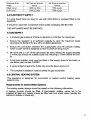
Expansion Vessel
The following table gives the maximum system volume that the integral 7 litre
expansion vessel can sustain.
Vessel charge/initial system pressure (bar)
Total water content of CH system (litres)
0.5
83
1
64
1.5
44
If the total water content exceeds that shown, an additional expansion vessel must
be fitted and connected to the heating system primary return pipe as close as
possible to the appliance. If an extra vessel is required, ensure that the total
capacity of both vessels is adequate. If the pressure display on the boiler control
panel indicates 2.2 bar or greater when the appliance is at maximum temperature
with all radiators in circulation an extra expansion vessel is required.
Pressure Relief Valve
A pressure relief valve set 3 bar (43.5psi) is fitted and a discharge pipe is routed to the
outside of the appliance. This discharge pipe should be extended to terminate safely
away from the appliance to a point where a discharge would not cause damage to
persons or property but would be detected. The pipe should be able to withstand
boiling water, be a minimum of 15mm in diameter, and not include any upward pipe
runs or horizontal runs prone to freezing.
4.7 DOMESTIC WATER SYSTEM
Check that mains supply pressure is within the prescribed range of 0.2 - 1Obar. If it
exceeds this limit, a pressure reducing valve should be fitted to the mains supply
before the inlet connection.
The final 1000 mm of the mains supply pipe to the boiler and the hot water outlet
must be in 15mm copper.
18
If the appliance is installed where the temporary hardness of the water is high,
say over 150 ppm (as defined by BS 7593 1993 Table 2), the fitting of an in line
scale inhibitor is required. This must be comply with the requirements of the local
water company.
Devices capable of preventing the flow of expansion water: e.g. non return valves
and/or loose - jumpered stop cocks should not be fitted unless separate
arrangements are made for expansion water.
If a non-return valve is fitted in the incoming water supply - e.g. in line with scale
inhibitor then a D.H.W. expansion vessel MUST be obtained and fitted.
4.8 INSTALLATION IN A BATHROOM
The appliance is rated IPX4D
The boiler may be installed in any room or internal space, although particular
attention is drawn to the requirements of the current IEE (BS.7671) Wiring
Regulations and, in Scotland, the electrical provisions of the building regulations
applicable in Scotland, with respect to the installation of the boiler in a room or
internal space containing a bath or shower. For IE reference should be made to
the current ETCI rules for electrical installations and I.S. 8 13:2002
If the appliance is to be installed in a room containing a bath or shower then the
appliance can be installed in Zones 1 & 2, as detailed in BS. 7671. Although
consideration must also be given when fitting boilers within bathrooms to adhere
to the current gas safety regulations.
19
20
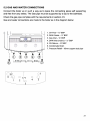
5.2 GAS AND WATER CONNECTIONS
Connect the boiler up in such a way as to leave the connecting pipes self supporting
and free from any stress. The Gas pipe must be supported by a clip to the bulkhead.
Check the gas pipe complies with the requirements in section 4.5.
Gas and water connections are made to the boiler as in the diagram below:
1. CH Flow-%" BSP
2.
3.
4.
5.
DHW Outlet- %" BSP
Gas Inlet-%" BSP
DHW Inlet (mains)-%" BSP
CH Return - %" BSP
6. Condensate Drain
7. Pressure Relief- 15mm copper stub pipe
I
' '
CD ®
®
07
0 171
2 ~
0
4
05
3
21
5.3 WIRING INSTRUCTIONS
Warning: observe the usual precautions to ensure that the electricity supply is
isolated before commencing any installation or service work.
The appliance is fitted with a 3 amp. fused 3 pin plug for use with 230 V-50Hz. It
should be fitted to a shuttered socket outlet complying with BS 1363. If the
appliance needs to be wired to a fused spur (for example in a bathroom) then the
3 pin plug should be removed and fitted to a double pole type 3A fused spur.
WARNING: THIS APPLIANCE MUST BE EARTHED.
Room ThermostatfTime Clock/Programmer
This appliance may be used in conjunction with an external control device.
This device MUST HAVE a volt free contact used to switch the boiler on and off. If
mains voltage enters the boiler via the control device terminals then BOILER
DAMAGE WILL OCCUR. If in doubt contact a qualified electrician.
For the connection of a control device proceed as follows:
1. Remove front casing
2. Lower control box by removing the 2 side screws
3. Undo the 2 screws securing the connection cover panel.
4. Remove the link wire (coloured blue as below)
5. Connect volt free heating control switch wire
If fitting a room thermostat. it must be installed on a wall which is free from any
objects and free from sunlight or draughts.
X7A
I erminal Block--
Room stat
N
L
It is possible to fit a 230VAC Thermostat!Time Clock/Programmer - Please
contact Marco for advice on how to install.
22
5.4 AIR/FLUE SYSTEM
The flue system is a p~rt of the appliance and is approved as such. Use only flue
systems supplied by Marco that are approved for use with this boiler.
Both horizontal and vertical flues can be used with these boilers. The following
maximum flue lengths apply. These are based on the use of one elbow for the
horizontal flue and no elbows for the vertical flue.
Flue Type
Horizontal
Horizontal
Vertical
Vertical
Model
24CPM
30CPM
24CPM
30CPM
Maximum Flue Length
7m
4m
8m
Sm
Each 90 degree elbow added to the flue decreases the maximum length available
by 1m. Eacfl 45 degree elbow added to the flue decreases the max1mum len_gth
ayailable by 0.5m. Please contact Marco for more details when designing true
kitS.
The horizontal flue pipe may be cut down to the length required.
The flue must be fitted with a 2° or 3° downwards incline towards the boiler to
ensure condense flows back into the boiler.
In cold or humid weather, water vapour in the flue gas may condense when
leaving the flue terminal. Care must be taken when locating the boiler to avoid
pluming causing nuisance to the occupier of the adjacent property.
The installer must ensure that an adequate seal is formed between the inner and
outer pipe and the corresponding part in any elbow or connector. The connection
can be eased by the use of silicon based lubricant. Normal grease/oil or sealant
are not allowed.
The black glastic terminal must be positioned with the rain shield to the top on the
horizontal flue system.
The air/flue terminal must be exposed to the external air and allow free passage
of air across it at all times.
The
minimum
acceptable
dimension
between
the
terminal
and
obstructions/oQenings are outlined in chapter 4.2. For domestic and Park homes
refer to BS5440.
23
5.5 CONDENSATE TRAP
All condensing boilers generate condensate discharge. The amount of
condensate water depends on the working conditions of your appliance. This
can be up to 1. 7 litres per hour.
A plastic discharge pipe should be fitted to the outlet pipe of the condensate
trap using the black rubber connector provided and the pipe should run into
the drain point. Only plastic materials are suitable.
If the pipe work is not terminated within the Caravan Holiday Home or Park
Home any external pipes must be insulated against freezing and increased to
a 32mm diameter. Pipe work runs should be kept to the minimum possible.
All horizontal pipes must be connected at a slight 2 or 3 degree downwards
incline to ensure a good flow.
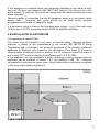
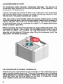
Before connecting the flue the condensate trap must be filled with water. This
is achieved by tipping 1 litre of water into the INNER flue terminal on top of
the boiler as below. This prevents the risk of products of combustion
escaping into the dwelling. Take care when filling the condensate trap if the
drain pipe is not already connected.
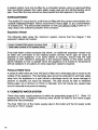
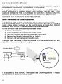
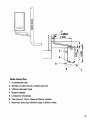
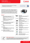
5.6 CONDENSATE DRAIN TERMINALS
National and local requirements for the connection of the condensate trap to
drains should be taken account of. There are 2 suggested ways of draining
the condensate for a Caravan Holiday or Park Home. One is to drain into the
waste pipe under the home as below and the other is to drain into a soak
away, details of which are on the following page.
24
- --· · -.·· ~ ''"-=
1
y ~f/J22
~500
0
0
~
' AI
4
5
- ----1"'·
.-----..::..---~...;
7
Soak Away Key
1. Condensate pipe
2. Section of pipe above or below ground
3. 100mm diameter pipe
4. Bottom sealed
5. Limestone chippings
6. Two rows of 12mm holes at 25mm centres
7. Minimum hole size 400mm deep x 300mm wide
25
6. COMMISSIONING
During commissioning the appliance, the following should be checked:
1.
2.
3.
4.
5.
6.
7.
Gas Supply
Water Supply
CH Circuit
Condensate Trap
Flue Connections
Electrical Circuit
Flue gas Analysis
IMPORTANT: Open all doors and windows, extinguish naked lights, and
DO NOT SMOKE whilst purging the gas line.
Before commencing the commissioning procedure, ensure that the central heating
system and the domestic hot and cold water system have been flushed. This will
remove contamination which could block the filters fitted to the cold inlet and C.H.
return connections resulting in incorrect functioning of the boiler.
6.1 GAS SUPPLY
The whole gas installation including the meter (if fitted) MUST be purged and
tested for gas soundness. Check the supply inlet pressure to the boiler is correct
for the type of gas used.
6.2 DOMESTIC HOT WATER
•
Turn on the mains cold water isolation valve.
•
Fill and vent the installation by turning on hot and cold water taps.
•
Make sure that there are no leaks in the installation.
GAS PRESSURE
TEST POINT
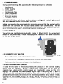
6.3 CENTRAL HEATING CIRCUIT
In order for the boiler to function correctly, the pressure in the central heating
circuit must be between 1.0 and 1.4 bar when cold. This can be seen by
pressing the button on the control panel and reading the value on the LCD
display. The pressure can be increased by the use of the filling loop - refer to
4.6. The central heating circuit should be filled with a mix of water and at least
25% antifreeze/inhibitor. In environments were temperatures drop below -11 deg
Celsius this percentage should be higher, with a maximum concentration of
40%. The concentration d anti freeze I inhibitor should be checked using a refractometer.
26
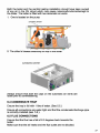
Both the boiler and the central heating installation should have been purged
of any air in the CH circuit which may cause noise/malfunctions/damage to
the boiler. The boiler is fitted with two automatic air vents:
1. One is located on the pump
AUTOMATIC AIR VENT
......
......
2. The other is located externally on top of the boiler
AUTOMATIC AIR VENT
Always ensure that both the caps on the automatic air vents are
loose prior to commissioning.
6.4 CONDENSATE TRAP
Ensure the trap is full with 1 litre of water. (See 5.5.)
Ensure all connections are water tight and that the condensate discharge pipe
is correctly installed (see 5.6.).
6.5 FLUE CONNECTIONS
Ensure that the flue has a fall of 2-3 degrees back towards the
boiler.
Make sure that the air intake and the flue outlet are not blocked.
27
6.6 ELECTRICAL CONNECTIONS
Checks to ensure electrical safety should be carried out by a qualified person
ALWAYS carry out the preliminary electrical system checks, i.e. earth continuity,
polarity, resistance to earth and short circuit using a suitable test meter.
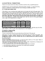
6.7 FLUE GAS ANALYSIS
If the boiler is on a metered gas supply carry out a gas rate test at the gas meter. The
boiler needs to be in service mode which is achieved by turning the CH knob on the
front panel fully clockwise and the service LED will now be on. Turn the knob counter
clockwise and then fully clockwise again and the service LED will flash. The boiler is
now set in “high-rate” service mode. Turn on the hot water tap and carry out a gas rate
test at the gas meter. The gas consumption should be as below within a tolerance of
5%. If the reading is outside of this range then, with the use of a flue gas analyser,
refer to gas valve adjustment in chapter 7.
Gas Consumption
Natural Gas (max load)
Natural Gas (min load)
Propane (max load)
Propane (min load)
24CPM 30CPM
2.38
2.92
0.71
0.88
1.77
2.17
0.64
0.77
Unit
m³/hour
m³/hour
kg/hour
kg/hour
If no meter is available or the boiler is on bottled gas then, with the use of a flue
gas analyser, refer to gas valve adjustment in the chapter 7.
6.8 INITIAL OPERATION
Domestic hot water
To turn on the boiler follow the user instructions at the front of this manual.
Whenever a hot tap is opened the boiler automatically fires up to deliver hot water. The
temperature selector control should be set at maximum. If the ambient water
temperature is high (as in a hot climate) then the hot water temperature may be reduced
by using this knob.
Central heating
Set the timer/thermostat/programmer so that the boiler will fire in CH mode. Refer to
chapter 1 User Instructions to operate the CH circuit.
The central heating temperature control knob allows water temperature of between 30
and 80°C to be selected. The boiler will remain on until:
• The temperature selected on the thermostat/programmer is reached
• The temperature selected on the boiler CH control knob is reached
• The timer switches the boiler off.
28
6.9 FAULT CODE/LOCK OUT
If the boiler develops a fault the reset button will show red and a fault code will show
on the LCD panel. See Fault codes in chapter 9 for further details.
To reset the boiler after a fault, press the reset button and it should change from red
to either:
• Clear if the boiler is unlit or
• Blue if the boiler is lit.
6.10 FINAL CHECKS
• Re-light and test for gas soundness
• Set the C.H. and D.H.W. temperature selectors to the required settings.
• Ensure that the timer/thermostat/programmer are set to the required settings.
6.11 USER INSTRUCTIONS
Upon Commissioning of the boiler the engineer should:
• Give the 'users Instructions' to the owner and emphasise their responsibilities
under the "Gas Safety (Installation and Use) Regulations 1998"
• Explain and demonstrate the lighting and shut down procedures.
• Advise the owner on the efficient use of the system, including the use and
adjustment of all system controls for both D.H.W. ana C. H.
• Advise the user of the precautions necessary to prevent damage to the system,
and tq the home, in the event of the system remaining inoperative during frost
cond1t1ons.
• Explain the function of the boiler safety devices, fault codes and how to reset
them. Emphasise that if fault codes and lock outs persist, the boiler should be
turned off and a Gas Safe Engineer consulted.
• Stress the importance of an annual service by a competent Gas Safe Registered
Engineer.
29
7. ROUTINE SERVICING
To ensure continued efficient operation of the appliance, it is recommended
that it is checked and serviced as necessary- at regular intervals. The frequency of servicing will depend upon the particular installation conditions and usage
but in generar once a year should be adequate.
It i~ the law that any service work must be carried out by a gas safe
reg1stered engmeer.
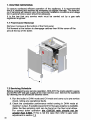
7.1 Front Cover Removal
Remove 2 screws at the bottom of the front panel
Pull forward at the bottom to disengage catches then lift the cover off the
pins at the top of the boiler.
..... ... .
...
..
......
7.2 Servicing Schedule
Before commencing any service operation, ISOLATE the mains electric supply,
and TURN OFF the gas supply at the main service cock. Service the appliance
by following the full procedure aetailed below.
1. Run the boiler in DHW mode and CH mode and carry out a pre service
check, noting any operational faults.
2. Check the combustion performance whilst running in DHW mode at
maximum output, if suitable equipment for flue gas analysis is available.
(Note: the flue sampling point can be found on the flue turret elbow.
For correct boiler operation the CO/C02 ratio should not be
greater than 0.004). If this is not the case then refer to gas valve
adjustment in section 7.3
30
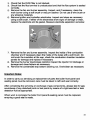
3. Check that the DHW filter is not blocked.
4. Check that the flue terminal is unobstructed and that the flue system is sealed
correctly.
5. Remove the fan and burner assembly. Inspect, and if necessary, clean the
main burner using a soft brush or vacuum cleaner. Do not use a wire brush or
any abrasive materials.
6. Remove ignition and ionization electrodes. Inspect and clean as necessary
using a soft brush. If either of the electrodes show signs of damage or wear,
replace the electrode and its gasket. Measure electrode separation as below:
7. Remove the fan and burner assembly. Inspect the inside of the combustion
chamber and if necessary clean the inside of the tubes with a soft brush. Do
not brush the insulation at the rear, check the combustion chamber insulation
panels for damage and replace if necessary
a. Remove the burner injector/gas restrictor.lnspect the injector for blockage or
damage and clean/replace as necessary.
9. Remove the condensate trap bottom cleaning nut. Drain/clean as necessary
Important Notes:
In order to carry out servicing or replacement of parts the boiler front panel and
sealing panel must be removed, care must be taken to refit and seal correctly.
After completing the servicing or exchange of gas components, always test for gas
soundness of any disturbed joints or test points by means of a tightness test or leak
detection fluid as appropriate.
When work is complete the boiler front panel & sealing panel must be replaced,
ensuring a good seal is made.
31
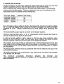
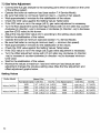
7.3 Gas Valve Adjustment
•
•
•
•
•
•
•
•
•
•
•
•
•
•
•
•
•
Connect the flue gas analyser to the sampling point which is located on the turret
of the air/flue system
Operate the boiler at maximum load (see section 7.4 Service Mode).
Be sure that boiler is running at maximum load (---+ maximum fan speed).
Wait approximately 4 minutes for the stabilisation of the values.
Check the C02 value against the Setting Values Table below
If the C02 value is not in the range (±0.2), gas valve adjustment is necessary.
Turn the flow adjustment screw (see figure below) with 2.5 mm allen key counterclockwise (in direction +ve) to increase or clockwise (in direction -ve) to decrease
gas flow (C02 value) to the burner.
Adjust the required C02 value (±0.1) according to the setting values table.
Wait for the stabilization of the values
Operate the boiler at minimum load (see section 7.4, Service Mode).
Be sure that boiler is running at minimum load (---+minimum fan speed).
Wait approximately 4 minutes for the stabilization of the values.
Check the C02 value against the Setting Values Table below
If the C02 value is not in the range (±0.2) gas valve adjustment is necessary.
Turn the offset adjustment screw with 2.5 mm allen key clockwise (in direction
+ve) to increase or counter-clockwise (in direction -ve) to decrease minimum
C02 value.
Wait for the stabilization of the values.
Recheck the values at maximum load and minimum load because each
adjustment changes the previous setting value (See the flow adjustment and
offset adjustment graphs below.
Setting Values
Boiler Model
Morco24CPM
Morco 30CPM
32
Natural Gas
Fan Speed (rpm) C02 (%)
1620
8,7 (±0,1)
9,3 (±0,1)
4680
1620
8,5 (±0,1)
9,0 (±0,1)
4800
02(%) Fan Speed (rpm)
5,6 (±0,2)
1860
4,5 (±0,2)
4440
6,1 (±0,2)
1860
5,1 (±0,2)
4440
Propane
C02 (%)
10,0 (±0,1)
10,8 (±0,1)
9,7 (±0,1)
10,8 (±0,1)
02(%)
5,7 (±0,2)
4,4 (±0,2)
6,2 (±0,2)
4,4 (±0,2)
1
- - - Boiler Load
{Fan Speed)
a) Flow Adjustment
- - - Boller Load
{Fan Speed)
b) Offset Adjustment
FEEDBACK CONNECTION
FlOW(CO)
ADJUSTMENT
SEALING L A B E L \ - -
:
,'
OFFSET
ADJUSTMENT
_/
-
--
l
SEALI NG lABEL
,
7.4 Service Mode
•
•
•
•
•
Turn the CH knob fully clockwise. Status LED Service will be ON
After the soft start time ends, the boiler will run at the minimum load.
To operate the boiler at the maxmum load, turn the CH knob to the off position
and back again to the service mode position within 3 seconds. (If the CH knob
stays in off position, the main board will cancel the service mode). The
status LED Service will blink to indicate the maximum load.
Service mode will be inactive after 10 minutes.
It is possible cancel the soft start function by turning the CH knob to the
off position and back again to the service mode position within 3 seconds.
33
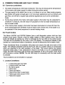
8. COMMON PROBLEMS AND FAULT CODES
8.1 Common problems
•
Hot water temperature at the taps is reduced. This may be because the temperature
of the mains cold water supply is colder during the winter period.
The gas supply to the boiler has run out, or is about to run out. Near empty propane
gas bottles will supply enough gas to run low power appliances such as cookers and
gas fires, but will fail to supply high powered appliances such as the combination
boiler.
During busy periods, the mains cold water supply to the boiler may be subjected to
variations in pressure, this will result in fluctuations in the hot water temperature at
the hot water outlet.
If the mains power supply to the boiler has been interrupted or turned off, then the
time clock/programmer (if fitted) must be reset to the correct time, if the boiler is to
be operated in the timed sequence in central heating mode.
•
•
•
8.2 Fault Codes
The Marco 24 CPM and 30 CPM Boilers have a self diagnostic system built into their
printed circuit board. Should a fault for safety related or other reasons occur, then the
boiler will failsafe by locking out, which is indicated by the red LED on the control panel.
The fault can be identified by the code in the LCD display. The electronic failsafe is also
backed by a mechanical means of protection, should the electronics fail to detect a fault.
These mechanical forms of protection will protect and ensure the safe shut down of the
boiler. The software protection built into the P.C.B. will run a system check on components
which are essential to the safe operation of the boiler. This occurs before any ignition
sequence takes place, if any component is found to be faulty or out of a predetermined
range, the boiler will lockout with the fault code displayed on the LCD screen. Each Fault
will comprise a number. NOTE: The red LED stays on constantly until the reset button
is pressed.
Fault conditions can be divided in 2 groups:
1. Lockout Conditions
•
•
•
•
•
•
•
•
34
Lockout flue gas over heat
Lockout boiler over heat
No flame signal
Flame loss
Flame simulation
Failure flow-return supervision
Failure gas valve circuit V1N2
Failure fan speed
These fault codes can only be cleared by pressing the reset push-button, then display
panel will be in stand-by mode. While in lockout conditions, Burner LED will turn RED.
2. Blocking Conditions
•
•
•
•
•
•
Boiler over heat
Failure CH flow sensor (NTC)
Failure flue gas sensor (NTC)
Failure CH return sensor (NTC)
Failure power supply
Failure water pressure
These fault codes will reset as soon as the cause of the problem disappears. For
example, when CH water pressure is out of operating range, blocking condition will be
generated and keep the system off until the pressure is within operating range again.
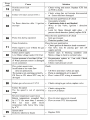
8 .3 Lockout Conditions and Solutions
-
Error
code
NO
lCD
Lack of electricity.
display
Lockout flue gas overheat
01
Solution - Check list
Cause
The flue gas sensor sensed
(over 105 °C.)
I
Power supply connections. Check
;.... On I off switch is ON
)3 amp fuse in fuse spur or 4amp fuse PCB
Lack of circulation, Check
;;;. Flow & Return isolation valves are open .
~
Ful1 TRV system have a by-pass
.,. By-pass settings
,,., Pump failure or set to maximum 3 setting
Faulty Flue-gas NTC or wire detached
.,
01 .
- Lack of circulation, Check
j;.
Flow & Return isolation valves are open.
Lockout boiler overheat
~
Full TRV systems have a by-pass
CH flow temp. has exceeded t 05 °C ~ By-pass settings
Pump tai lure or set to maximum3 setting
or CH return temp. exceeds 90 °C
:.. Faulty Flow I return NTC or wire detached
06
Boiler overheat
CH flow temp has exceeded 95 °C
or return temp. exceeds 90°C,
,.
,..
Boiler will remain in this error mode until
flow temperature drops into operating range.
Heat exchanger overheat stat
12
13
);.
Thermal cut-off 160 °C may have
operated.
Flue gas NTC Open circuit
Check Thermal cut out in heat exchanger for
continuity.
If boiJer is cold ;... Check wiring has not become disconnected or
Sensor has been damaged.
~
Replace NTC
35
36
9 . WARRANTY CONDITIONS
The boiler is guaranteed against manufacturing defects for a period of one year from the
date of first commissioning. However the guarantee is subject to proof of commissioning
in accordance with the gas safety (Installation and Use) act. 1998.
The guarantee does NOT cover the following issues:
•
•
•
•
•
•
•
Frost damage to any part of the boiler containing water during freezing conditions.
The removal of sludge or hard water scale due to lack of antifreeze/inhibitor or water
quality.
Damage to electronics caused by a defective electrical supply.
Damage or failure caused by insect contamination or blocked water filters.
Loss off pressure within the heating system not caused directly by the boiler.
Incorrect operation of the boiler caused by defective outlets such as thermostatic
mixers or mono block mixer taps.
Damage caused by unauthaurised modifications to the boiler from original specifications.
For more detailed servicing information, workshop manuals, technical advice, spare
parts, product training, please contact us at the address below.
MORCO PRODUCTS LTD
Marco House, Riverview Road, Beverley, East Yorkshire HU17 OLD
TEL: 01482 325456
FAX: 01482 212869
EMAIL: [email protected]
www. morcoproducts.co.uk
37