1
HSM-CD7
Rutherford Decorator
High Speed Logic Module
User’s Manual
Systems Engineering Associates, Inc.
14989 West 69th Avenue
Arvada, Colorado 80007 U.S.A.
Telephone: (303) 421-0484
Fax: (303) 421-8108
www.sea-seg.com
02/2004
HSM-CD7
Rutherford Decorator
High Speed Logic Module
User’s Manual
Copyright © 2001 Systems Engineering Associates, Inc.
All Rights Reserved!
Revised 4 February 2004
WARNING
To ensure the equipment described by this User Manual, as well as the equipment connected to
and used with it, operates satisfactorily and safely, all applicable local and national codes that
apply to installing and operating the equipment must be followed. This includes the National
Electric Code in the USA and other applicable legislation, regulations, and codes in practice
elsewhere. Since codes can vary geographically and can change with time, it is the user’s
responsibility to determine which standards and codes apply, and to comply with them.
FAILURE TO COMPLY WITH APPLICABLE CODES AND STANDARDS CAN RESULT IN
DAMAGE TO EQUIPMENT AND/OR SERIOUS INJURY TO PERSONNEL.
Persons supervising and performing installation or maintenance must be suitably qualified and
competent in these duties, and should carefully study this User Manual and any other manuals
referred to by it prior to installation and/or operation of the equipment.
The contents of the User Manual are believed to be correct at the time of printing; however, no
responsibility is assumed for inaccuracies. In the interests of a commitment to a policy of
continuous development and improvement, the manufacturer reserves the right to change the
specification of the product or it’s performance or the contents of the User Manual without notice.
Copyright © 2001 Systems Engineering Associates, Inc.
All Rights Reserved !
CONTENTS
1. General Description
1.1
1.2
1.3
1.4
1.5
1.6
1
Features
Functional Description
Speed Compensated Print Carriage Trip
and Varnish Unit Control
Bad Can and Select-A-Can Pin Chain Blow-off
Alarm Detection
Data Collection
2. Installation
2.1
2.2
2.3
2.4
2.5
2.6
2.7
2.8
2.9
1
2
3
3
4
5
7
What's Included
Power Required
Mounting the HSM-CD7
Wiring the HSM-CD7
Mounting the HSL-QCSTA
Mounting the HSL-DSP Remote Display
Mounting the RSV34-MS1 Resolver
Mounting the Spindle #1 I.D. Sensor
HSM-CD7 Software Installation
2.9.1 Windows Based Setup Program Installation
2.9.2 DOS Based Setup Program Installation
2.9.3 SYSdev Program Development Software
Installation
2.9.4 Application Program Installation
7
7
8
9
10
10
11
11
12
12
13
14
15
2.10 Modify Existing PLC Program
2.11 Tuning the HSM-CD7
2.11.1 Default Set-Up Variables
2.11.2 Set Machine Zero
2.11.3 Verify Location of Can/No Can Sensor
2.11.4 Set Pin Chain Blow-off Timing
2.11.5 Set # of Pins to Pin Chain Blow-off Port
2.11.6 Set # of Cans to Blow-off at Restart
2.11.7 Set # of Cans from Infeed to Can PRX
2.11.8 Set Print Carriage and Varnish Unit
"Retract"/"Extend" Response Times
2.11.9 Set QC Blow-off Shift Offset
2.11.10 Set Blanket Wheel Segments
2.11.11 Set Spindle Trip Offset
16
18
19
20
21
22
23
24
25
2.12 HSM-CD7 Module Replacement
30
HSM-CD7 User’s Manual
26
27
28
28
SYSTEMS Electronics Group
-i-
CONTENTS
3. Using the Keypad/Display
33
3.1
3.2
3.3
3.4
3.5
Default Screen
"Trips per Spindle" Key
"Current Shift" Key
"Last Shift" Key
"Set-up" Key
3.5.1 Set Carriage/Varnish Response Times
3.5.2 Set Pin Chain/QC Blow-off Parameters
3.5.3 Set Machine Timing (Set-Points, etc.)
3.5.4 Set Number of Shifts to Varnish Unit
3.5.5 Zero Machine (Set Resolver Offset)
3.5.6 View Critical Input Positions
34
34
35
36
37
37
39
41
43
43
44
3.6
"QC Blow-off" Key
45
4. RTFCD7 Windows Based
Set-up Program Reference
47
4.1
4.2
General Description
The File Menu
4.2.1 The Set-Up Data File
4.2.2 Upload (save) Data
4.2.3 Download Program
4.2.4 Download (restore) Data
4.2.5 Print Report
48
49
50
52
53
54
55
4.3
The Edit Menu
4.3.1 Enable Offline Editing
4.3.2 Setup Comm Port
56
56
57
4.4
The View Menu
4.4.1 Target Board Interface
4.4.2 View Online Data
4.4.3 View Offline Data
58
59
60
60
4.5
The Window Menu
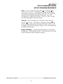
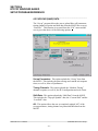
4.5.1 The Main Display Window
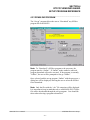
4.5.2 The Setup Parameters Window
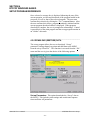
4.5.3 The Serial Communications Window
4.5.4 The Machine Timing Window
4.5.5 The Shift Data Window
4.5.6 The I/O States Window
61
62
64
69
72
76
80
HSM-CD7 User’s Manual
SYSTEMS Electronics Group
- ii -
CONTENTS
5. HSMCD7 DOS Based
Set-up Program Reference
81
5.1
5.2
5.3
Set Carriage/Varnish Response Times
Set Pin Chain/QC Blow-off Parameters
Set Machine Timing
5.3.1 Zeroing the Machine
5.3.2 Adjusting the Timing Channel Set-points
82
84
86
88
89
5.4
5.5
5.6
5.7
5.8
5.9
Number of Trips per Spindle Data
Current Shift Data
Last Shift Data
Download Program to M4503
Download Set-up Data to M4503
Upload (save) Set-up Data from M4503
90
91
93
94
95
96
6. General Timing Signal Locations
97
7. Recommended Spare Parts
101
HSM-CD7 User’s Manual
SYSTEMS Electronics Group
- iii -
CONTENTS
LIST OF FIGURES
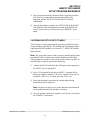
HSM-CD7 Recommended Panel Door Cut-out
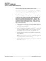
Machine Zero Position
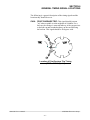
Location of Can/No Can Sensor
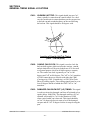
Location of Blow-off Timing “ON” Position
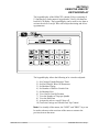
Keypad/Display Legend
Location of Print Carriage trip timing (CH00)
Location of Varnish Unit Trip Timing (CH01)
8
20
21
22
33
97
98
APPENDICES
MODBUS Communications
MODBUS Port Configuration
Data Written to the MODICON PLC
Data Read from the MODICON PLC
Appendix A
A-1
A-1
A-4
Allen-Bradley DF1 Communications
Hardware
Software
Using the MSG Instruction
Channel 0 Setup
Read/Write Data Definitions
Appendix B
B-1
B-3
B-5
B-9
B-12
Drawings
Appendix C
HSM-CD7 User’s Manual
SYSTEMS Electronics Group
- iv -
SECTION 1
GENERAL DESCRIPTION
This section describes the features of the HSM-CD7 Rutherford
Decorator/Basecoater High Speed Logic Module. This includes the
functional description, alarms detected, etc.
________________________________________________________
1.1 FEATURES
Performs high speed control functions of Rutherford
Decorator/Basecoater to speeds in excess of 2000 CPM. This includes
detection of mis-loaded cans, damaged can blow-off, speed
compensated print carriage and varnish unit trip, and three can pin
chain (bad can) blow-off.
•
High speed front-end upgrade package which interfaces with
existing control system.
•
Accurate damaged can blow-off prior to the print station
eliminates cut blankets.
•
Speed compensated print carriage trip control and varnish unit trip
control eliminates inside deco and varnish problems.
•
Accurate speed compensated three can (bad can) pin chain blowoff reduces scrap and eliminates silver and partially printed cans
down the line.
•
Single select-a-can QC pin chain blow-off allows operator to blow
off a can from a selected spindle (or blanket) to verify print
quality of each blanket with machine running at full production
speeds.
•
Alarm detection: infeed track jam, no can transfer (can on
mandrel), and timing signal fail detection.
•
Data Acquisition: Total number of good cans printed, total
number of blow-offs, trips per spindle, etc. (for both current shift
and last shift).
•
Built-in 2 Line X 40 character sealed display with 24 key
membrane keypad allows local viewing of collected data (can
count, blow-off count, trips per spindle) by operator and set-up of
all user variables (passcode protected or key switch enabled) by
authorized personnel.
HSM-CD7 User’s Manual
SYSTEMS Electronics Group
-1-
SECTION 1
GENERAL DESCRIPTION
•
Interfaces directly with machine mounted resolver, can/no can
sensor and all trip and blow-off solenoids.
•
Based on high performance M4500 PLC/PLS module which
allows easy trouble-shooting and user customization using
SYSdev (DOS-based) programming package.
•
Built-in PLS provides all machine timing, eliminating need for an
additional PLS.
•
Can be used on all Rutherford Basecoaters (both carriage trip
models and two coater roll models) as well as all Rutherford
Decorator models.
________________________________________________________
1.2 FUNCTIONAL DESCRIPTION
The HSM-CD7 Decorator/Basecoater high speed logic module is an
electronic upgrade for the Rutherford decorator/basecoater which
detects miss-loaded cans, performs speed compensated print trip,
varnish trip, and three can (bad can) blow-off at speeds in excess of
2000 CPM. In addition, the package provides select-a-can pin chain
blow-off for print quality verification of each blanket.
Alarm detection is provided including: infeed track jam, no can
transfer (can on mandrel), and timing signal failure. Data collection
includes: Total good can count, blow-off counts, and trips per spindle
(both for the current shift and previous (last) shift. The package
interfaces directly to the machine mounted resolver, can/no can
sensor, trip and blow-off solenoids as well as the host PLC via
discrete DC I/O.
The package is not a dedicated "black box", but is instead
implemented using the high performance SYSTEMS M4500
PLC/PLS module allowing easy customization by either SEA or the
end user. The M4503 module is programmed using the DOS-based
SYSdev programming package. This allows the module to be
programmed in any combination of Ladder or High-level (subset of
"C"), as well as perform on-line monitoring and trouble-shooting. The
M4503 module incorporates a built-in PLS which interfaces directly
with the machine mounted resolver and provides all machine timing,
eliminating the need for an external PLS.
HSM-CD7 User’s Manual
SYSTEMS Electronics Group
-2-
SECTION 1
GENERAL DESCRIPTION
________________________________________________________
1.3 SPEED COMPENSATED PRINT CARRIAGE TRIP AND
VARNISH UNIT CONTROL
Speed compensated print carriage trip at speeds in excess of 2000
CPM is incorporated in the HSM-CD7 to compensate for the trip
response time of the carriage. The print carriage is always extended or
retracted such that a miss-loaded mandrel is not printed regardless of
machine speed.
The varnish unit control algorithm incorporates the same speed
compensation algorithm incorporated in the print carriage control.
The package achieves this by implementing a speed compensation
algorithm that "leads" the trip point by the response time of the
carriage. The control is capable of "leading" the trip point by up to
two stations (60msec at 2000 CPM).
Note: a single mandrel trip is possible at speeds up to 1200 CPM, a
two station trip is recommended for speeds above 1200 CPM.
________________________________________________________
1.4 BAD CAN AND SELECT-A-CAN PIN CHAIN BLOW-OFF
Both the bad can pin chain blow-off and select-a-can pin chain blowoff incorporate speed compensation to compensate for the response
time of the blow-off solenoids regardless of machine speed. This
allows accurate rejection of a single can from the pin chain at speeds
in excess of 2000 CPM. The bad can blow-off is activated
automatically to reject miss-loaded cans from the pin chain.
The select-a-can feature allows the user to dial in a mandrel number,
either at a remote PB station or from the keypad of the HSM-CD7,
and blow-off one can printed on that mandrel. Mandrels 1 through 24
can be individually blown-off this way to verify the print quality of
each mandrel. Two other select-a-can blow-off modes are also
available: blanket and mandrel. The blanket mode blows off
consecutive cans printed on each blanket, starting with blanket 1. The
mandrels mode blows off 24 consecutive cans printed on all 24
mandrels, starting with mandrel 1.
HSM-CD7 User’s Manual
SYSTEMS Electronics Group
-3-
SECTION 1
GENERAL DESCRIPTION
The following variables can be set by the user for the bad can blowoff:
• Number of shifts from machine to blow-off port (up to 999).
• Number of cans to blow-off for each bad can (three is usually
required when varnish is used).
• Both the "on" and "off" solenoid response times (used by the
speed compensation algorithm).
The following variables can be set by the user for the select-a-can
blow-off:
• QC shift offset (1 to 24) which is used to match the actual
mandrel number to the selected mandrel number.
• Number of blankets on blanket wheel.
• Both the "on" and "off" solenoid response times.
________________________________________________________
1.5 ALARM DETECTION
The package detects the following alarms:
Infeed Track Jam: The infeed track jam alarm occurs when 6
consecutive empty mandrels are detected by the "can/no can sensor"
after the can gate is opened.
No Can Transfer: The no can transfer alarm occurs when the "no
can transfer sensor" detects a can on a mandrel after the disk transfer
location.
Timing Signal Fail: The timing signal fail occurs when any of the
timing signals generated in the PLS section fail to change state
periodically while the machine is running.
The above alarms are available to the host PLC via discrete outputs.
These should be used to stop the machine and indicate the problem
when any one of the alarms occurs.
HSM-CD7 User’s Manual
SYSTEMS Electronics Group
-4-
SECTION 1
GENERAL DESCRIPTION
________________________________________________________
1.6 DATA COLLECTION
The following data is collected for both the current shift and the
previous (last) shift:
1)
2)
3)
4)
5)
6)
7)
Total number of good cans printed
Total number of cans blown-off
Total number of miss-loaded cans (bad cans)
Total number of restart blow-offs
Total number of manual blow-offs
Total number of select-a-can QC blow-offs
Total trips per spindle (for each spindle)
This data can be viewed locally on the display sent to the host PLC
via RS-232 communications (MODBUS or Allen-Bradley DF1
protocols) using the optional S4516 serial communications board.
This information is updated ("current" shift transferred to "Last" shift)
based on the change of state of a discrete input. This input can be
activated on an 8 or 12 hour shift basis or alternatively could be
activated manually on a label run basis depending on the user's
preference.
In addition to the shift data collection, a separate buffer is available to
collect trips per spindle counts as a diagnostics aid to the operator for
trouble-shooting a loading problem on a specific mandrel. Unlike the
shift data, these counts can be reset manually by the operator at will.
This allows the operator to note an abnormally high count on a
specific mandrel, attempt to correct the problem, reset the counts and
then check the counts at a latter time to determine if the problem is
corrected. This data is viewed on the Keypad/Display.
HSM-CD7 User’s Manual
SYSTEMS Electronics Group
-5-
SECTION 1
GENERAL DESCRIPTION
(This Page Intentionally Left Blank)
HSM-CD7 User’s Manual
SYSTEMS Electronics Group
-6-
SECTION 2
INSTALLATION
________________________________________________________
2.1 WHAT'S INCLUDED
Verify that the following items are included when unpacking the
HSM-CD7:
1ea.
1ea.
1ea.
1ea.
1ea.
HSM-CD7 M4503 Module with required I/O boards
HSM-CD7 User's Manual
HSM-CD7 Keypad Quick Reference
M4500 User's Manual
HSM-CD7 Program Disk
The following items are optional items and can be purchased
separately as required or desired:
1ea.
1ea.
1ea.
1ea.
HSL-QCSTA Remote Select-A-Can PB station
HSL-DSP Remote RPM/Position Display
RSV34-MS1 Resolver
RSV-RSCBLE-XX Resolver Cable
________________________________________________________
2.2 POWER REQUIRED
The HSM-CD7 is powered from 115VAC/230VAC 50/60HZ and
+24VDC. The 115VAC/230VAC is used to power the HSM-CD7
module while the +24VDC is used to power the +24VDC I/O
(sensors, trip and blow-off solenoids).
Note: +24VDC solenoids must be used for all trip and blow-off
solenoids. These provide a much more consistent and repeatable
response time than 115VAC solenoids. Assuming +24VDC solenoids
were used in the existing system, the +24VDC current required by the
HSM-CD7 is no more than the existing systems +24VDC current
requirement therefore the existing +24VDC power supply should be
adequate.
HSM-CD7 User’s Manual
SYSTEMS Electronics Group
-7-
SECTION 2
INSTALLATION
________________________________________________________
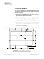
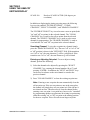
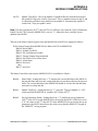
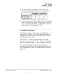
2.3 MOUNTING THE HSM-CD7
The HSM-CD7 module should be mounted in the door of the existing
user's cabinet or console door. Perform the following steps to mount
the HSM-CD7 module:
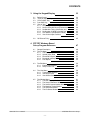
1) Referring to the recommended cut-out, cut a cut-out in the door of
the existing user's control cabinet or console.
2) Remove all the field wiring connectors from the top of the HSMCD7 module. With the gasket installed on the HSM-CD7 module
mounting studs, slide the module into the cut-out from the front.
Attach the module to the door using the supplied hardware.
3) Once the module is installed, a lugged earth ground wire should
be installed on one of the module mounting screws to insure that
the HSM-CD7 is well grounded.
________________________________________________________________________________
HSM-CD7 Recommended Panel Door Cut-out
HSM-CD7 User’s Manual
SYSTEMS Electronics Group
-8-
SECTION 2
INSTALLATION
________________________________________________________
2.4 WIRING THE HSM-CD7
Referring to the electrical control schematic at the back of this
manual, wire the HSM-CD7 as follows:
Note: The HSM-CD7 contains removable field wiring connectors for
ease of maintenance. It is generally easier to perform the wiring
described below with the connectors removed from the module and
install the connectors once all wiring is complete.
In general, when wiring the HSM-CD7, keep all +24VDC wiring,
resolver cable, and sensor cable wiring away from high voltage
wiring.
1) Incoming Power: 115VAC-230VAC to L, N, and G of HSM-CD7
power connector and +24VDC to I/O connectors.
2) Interlocks from existing control system to HSM-CD7 (inputs
B100.0 - B100.7, B101.0, B101.1, B101.2).
3) Interlocks to existing control system from HSM-CD7 (outputs
B121.4, B121.5, B121.6, and B121.7).
4) Carriage Trip, Varnish Unit Trip, Damaged Can Blow-off, Pin
Chain Blow-off, and Can Feed solenoids.
5) Can/No Can Sensor, Spindle No.1 I.D. Sensor, and No Transfer
Sensor using three conductor, shielded cables. The shields of the
sensor cables should be tied to earth ground at a terminal inside
the existing control cabinet and left floating at the sensors.
6) Set-Up Enable key switch (if desired) to allow entry to set-up
variables through Keypad/Display (input B101.4).
7) Resolver cable from resolver (or existing PLS) to 8-pin resolver
input connector on HSM-CD7 using a three pair, two conductor
shielded cable. The shield of the resolver cable should be tied to
the "SHLD" terminal of the HSM-CD7 resolver input connector.
Make sure the resolver cable shield is left floating at the resolver.
HSM-CD7 User’s Manual
SYSTEMS Electronics Group
-9-
SECTION 2
INSTALLATION
________________________________________________________
2.5 MOUNTING THE HSL-QCSTA
The HSL-QCSTA is used to blow-off a can from a selected spindle
(or blanket) from the pin chain for quality verification. If the optional
HSL-QCSTA remote select-a-can PB station was purchased, mount it
in the vicinity of the pin chain QC blow-off port in a convenient
location for the operator. Wire the HSL-QCSTA to the HSM-CD7
module referring to the electrical control schematic at the back of this
manual.
________________________________________________________
2.6 MOUNTING THE HSL-DSP REMOTE DISPLAY
The HSL-DSP is a remote 4 digit BCD display which displays either
the current CPM or resolver position as selected by the operator. If
the optional HSL-DSP remote RPM/Position display was purchased,
make a cut-out in the operator's control console for the display where
desired.
Prior to mounting, remove the back cover of the display and set the
dip switches as outlined on the electrical control schematic at the back
of this manual. Mount the display and wire per the schematic at the
back of this manual. A selector switch can also be mounted and wired
as shown to select either CPM or position.
HSM-CD7 User’s Manual
SYSTEMS Electronics Group
- 10 -
SECTION 2
INSTALLATION
________________________________________________________
2.7 MOUNTING THE RSV34-MS1 RESOLVER
(IF REQUIRED)
The HSM-CD7 is designed to interface to a resolver (not encoder) for
machine timing. If the machine is not already equipped with a
resolver, then the existing encoder will have to be removed and an
RSV34-MS1 resolver will have to be mounted in it's place. If this is
the case, refer to the RSV34-MS1 data sheet for details on mounting
the resolver.
Note: The resolver must make one revolution for each spindle (24
revolutions per spindle wheel revolution). Use the RSV-RSCBLE
cable to connect the resolver to the HSM-CD7. Route the resolver
cable in a separate conduit, away from all other high voltage and
control wiring. Wire the cable directly to the 8-pin resolver connector
on the HSM-CD7 (see section 2.4 – Wiring the HSM-CD7).
________________________________________________________
2.8 MOUNTING THE SPINDLE #1 I.D. SENSOR
(NOT PROVIDED)
If the machine is not already provided with a spindle #1 I.D. sensor,
then one will have to be mounted. This sensor is used to determine
which spindle is the #1 spindle for both the QC select-a-can blow-off
and the trips per spindle count. This must see a target once every
revolution of the spindle wheel (once every 24 spindles). Any nondiscriminating 10-30VDC proximity sensor can be used and it can be
mounted anywhere around the periphery of the spindle wheel. The
target it looks at should be either a large steel bolt head or 1" by 1"
square steel target mounted on the spindle wheel in the vicinity of
spindle #1.
HSM-CD7 User’s Manual
SYSTEMS Electronics Group
- 11 -
SECTION 2
INSTALLATION
________________________________________________________
2.9 HSM-CD7 SOFTWARE INSTALLATION
Follow the steps below to install either the Windows or DOS based
setup programs and PLC application program on a PC used to support
the HSM-CD7 control system.
________________________________________________________
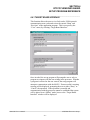
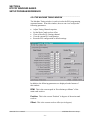
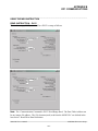
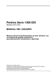
2.9.1 WINDOWS™ BASED SETUP PROGRAM
INSTALLATION
The RTFCD7 setup program is compatible with Windows
95/98/ME/2000/XP operating systems and is used to:
1) Setup (tune) the user adjustable variables.
2) Adjust the timing channel set-points.
3) Download the application program to the M4503 module.
4) Download (restore) or upload (save) the user setup variables
from the M4503.
5) View “Shift” and “Trips per Spindle” data.
To install the set-up software, perform the following steps:
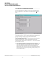
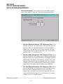
1) Insert the HSM-CD7 CD into the drive
2) From the Windows desktop, “Click” Start and then select run.
3) From the “Run” dialog box, “Click” the Browse button.
4) Select the drive with HSM-CD7 CD. Select the “setup.exe” file
and “Click” Open and then Ok.
5) This will initiate the installation process. Follow the instructions
that appear on the screen to complete the installation process. The
RTFCD7 setup program can be executed from the “Systems”
folder located in Programs.
HSM-CD7 User’s Manual
SYSTEMS Electronics Group
- 12 -
SECTION 2
INSTALLATION
________________________________________________________
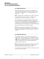
2.9.2 DOS BASED SETUP PROGRAM INSTALLATION
Follow the steps below to install the HSM-CD7 Set-up software
package onto a PC used to support the HSM-CD7 package.
The HSMCD7 set-up software is used to
1) Setup (tune) the user adjustable variables.
2) Adjust the timing channel set-points.
3) Download the application program to the HSM-CD7 module.
4) Download (restore) or upload (save) the user setup variables
from the M4503 to disk.
5) View “Shift” and “Trips per Spindle” data.
To install the DOS based set-up software perform the following steps:
1) Create one directory off the root directory of the PC for each
decorator the HSM-CD7 will be used on called "HSMDEC1" for
the line 1 decorator, "HSMDEC2" for the line 2 decorator,
"HSMDEC3" for the line 3 decorator, etc. These will be used to
store the "HSMCD7.EXE" setup programs and HSMCD7 set-up
data for each decorator. Create these directories by typing the
following at the DOS prompt:
MD \HSMDEC1<ENTER>
MD \HSMDEC2<ENTER>
MD \HSMDEC3<ENTER>
etc.
2) Install the "PROGRAMS" disk into the drive. For each
"HSMDEC" directory you created in the previous step, switch to
that directory and install the "HSM-CD7" set-up programs by
typing the following at the DOS prompt (Line 1 decorator is
shown):
CD \HSMDEC1<ENTER>
A:INSTALL<ENTER>
HSM-CD7 User’s Manual
SYSTEMS Electronics Group
- 13 -
SECTION 2
INSTALLATION
3) Add each decorator's HSM-CD7 set-up program to your
computer's menu software by creating a selection for each
decorator called "SET-UP DECO LINE1" for the line #1
decorator, "SET-UP DECO LINE2" for the line #2 decorator, etc..
The DOS commands executed for these selections should be:
For the "SET-UP DECO LINE1" selection:
CD \HSMDEC1
HSMCD7 HSMCD7
CD \
For the "SET-UP DECO LINE2" selection:
CD \HSMDEC2
HSMCD7 HSMCD7
CD \
etc.
4) To execute the respective decorator's set-up program, simply
select the corresponding "SET-UP DECO LINE" selection from
the menu software's menu.
________________________________________________________
2.9.3 SYSdev PROGRAM DEVELOPMENT SOFTWARE
INSTALLATION
The SYSdev Program Development software is used to perform online trouble-shooting and program modifications to the HSM-CD7. If
SYSdev was purchased with the HSM-CD7 package and is not
already installed on the your computer, install SYSdev onto the hard
drive of your computer following the steps outlined in the SYSdev
Program Development manual.
HSM-CD7 User’s Manual
SYSTEMS Electronics Group
- 14 -
SECTION 2
INSTALLATION
________________________________________________________
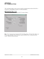
2.9.4 APPLICATION PROGRAM INSTALLATION
The HSMCD7 application program is a SYSdev based program which
is loaded into the HSM-CD7 module and performs the HSM-CD7
logic. The HSMCD7 program is written in a combination of Ladder
logic and High-level. If the user desires to make program changes or
perform on-line monitoring of the program execution, the files which
constitute the HSMCD7 program will have to be loaded onto the hard
drive of the PC which is used to support the HSM-CD7. The SYSdev
Program Development Software will also have to be loaded on the
PC. To install this program perform the following:
1) If not already done, perform steps 1 through 3 of section 2.9.2 –
DOS Based Setup Program Installation. This creates the
directories and menu selections, which will be used to store and
select the HSMCD7 application programs.
2) Install the disk labeled "HSM-CD7 PROGRAMS" into the A:
drive. For each of the "HSMDEC" directories, switch to that
directory and install the HSMCD7 application program by typing
the following at the DOS prompt (Line 1 decorator is shown):
CD \HSMDEC1<ENTER>
COPY A:HSMCD7.*<ENTER>
CD \
3) Add the HSMCD7 application programs to your computer's menu
software by creating selections called "HSM-CD7 PROGRAM
LINE1", etc. for each decorator. The DOS commands executed
for these selections should be (Line 1 decorator shown):
CD \
SYSDEV \HSMDEC1 HSMCD7
4) To initiate SYSdev with the "HSMCD7" program, simply select
the respective "HSM-CD7 PROGRAM" selection from the menu
software's menu. The main development menu of SYSdev will be
initiated with the HSMCD7 program. See the SYSdev Program
Development manual and the M4500 Program Development
manual for complete details on on-line monitoring and program
development with SYSdev.
HSM-CD7 User’s Manual
SYSTEMS Electronics Group
- 15 -
SECTION 2
INSTALLATION
________________________________________________________
2.10 MODIFY EXISTING PLC PROGRAM
Modify the existing control system PLC program to interface with the
HSM-CD7 by incorporating the following into the existing PLC
ladder logic:
1) The HSM-CD7 now controls the damaged can blow-off, print
carriage trip, varnish unit trip, and pin chain blow-off. If the
existing host PLC was previously controlling these functions, it
no longer will be with the addition of the HSM-CD7. This logic
can optionally be removed from the existing host PLC if desired.
In most cases this logic can be left in the program as connecting
the respective solenoids to the HSM-CD7 will effectively defeat
the logic.
2) Add the "Infeed Track Jam" and "Can On Mandrel (no transfer)"
alarms as inputs to the host PLC. These should stop the machine
anytime either of these alarms are "on".
3) Add the "Carriage Auto Mode" and "Carriage Manual In" outputs
into the PLC logic. When both are "off" the carriage will be
retracted. When the "Manual In" is "on", the carriage will be
extended (print position). When the "Auto Mode" is "on", the
carriage is controlled by the can/no can sensor.
4) Add the "Varnish Auto Mode" and "Vanish Manual In" outputs
into the PLC logic. When both are "off" the varnish unit will be
retracted. When the "Manual In" is "on", the varnish will be
extended (varnish position). When the "Auto Mode" is "on", the
varnish unit is controlled by the can/no can sensor.
5) Add the "Damaged Can Auto Mode" and "Damaged Can Manual
On" outputs into the PLC logic. When both are "off" the damaged
can blow-off is disabled. When the "Manual On" is "on", the
damaged can blow-off is "on". When the "Auto Mode" is "on",
the damaged can blow-off is controlled by the can/no can sensor
and infeed open.
6) Add the "Pin Chain Manual Blow-off" output to the PLC logic.
This can be used as a manual blow-off. When "on", the bad can
pin chain blow-off is "on". When "off", the pin chain blow-off
functions normally, blowing off detected bad cans, restart cans,
etc.
HSM-CD7 User’s Manual
SYSTEMS Electronics Group
- 16 -
SECTION 2
INSTALLATION
7) Add the "Can Feed Open" output to the PLC logic. When turned
"on" while running, the infeed is timed "open" with the can feed
timing signal. When turned "off" while running, the infeed is
timed "closed" with the can feed timing signal. When the machine
is stopped, turning this input "on" and "off" will respectively
"open" and "close" the can stop.
8) Add the "Main Drive On" output to the PLC logic. This should be
"on" when the drive is enabled (running) and should be "off"
when the drive is disabled (this includes auto stop conditions).
This is true for jog modes as will.
9) Add the "Alarm Reset" output. This signal should be "on" as long
as the system reset push-button is depressed.
HSM-CD7 User’s Manual
SYSTEMS Electronics Group
- 17 -
SECTION 2
INSTALLATION
________________________________________________________
2.11 TUNING THE HSM-CD7
The HSM-CD7 is shipped from the factory with the PLC application
program loaded in the HSM-CD7 module (PLC section) and the PLS
channel set-point file "CD7TMG" loaded in the PLS section. These
standard programs are used to implement the decorator or basecoater
algorithms. In most cases, the following user variables and timing
signals may have to be altered to tune the HSM-CD7 to the actual
decorator it is controlling.
Once the system is installed and powered back up, perform the
following to set-up and tune the HSM-CD7. The set-up is performed
using either the Keypad/Display or a PC running the set-up program.
See the HSM-CD4/CD7 Keypad Quick Reference for key depress
sequences for entering the following parameters. See section 3 of this
manual for a description of the keypad commands and menu displays
of the Keypad/Display. See sections 4 and 5 for a description of
menus and how to use the set-up programs.
HSM-CD7 User’s Manual
SYSTEMS Electronics Group
- 18 -
SECTION 2
INSTALLATION
________________________________________________________
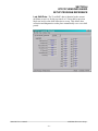
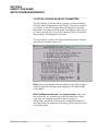
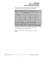
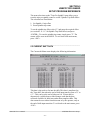
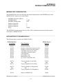
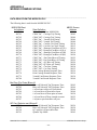
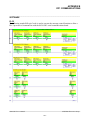
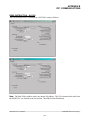
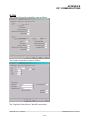
2.11.1 DEFAULT SET-UP VARIABLES
As shipped, the user variables for the HSM-CD7 are set the following
defaults:
Print Carriage and Varnish Unit:
Print Carriage retract response time (msec)
Print Carriage extend response time (msec)
Varnish Unit retract response time (msec)
Varnish Unit extend response time (msec)
Number of Shifts to Varnish Unit
:
:
:
:
:
045
045
060
060
5
Bad Can (pin chain) Blowoff:
# of bad cans to blowoff for misload
# of cans to blowoff from infeed open
# of cans to blowoff from print at restart
# of cans to blowoff from varnish at restart
# of pins to pin chain blowoff port
# of cans from infeed to can PRX
Blow-off solenoid "on" response time (msec)
Blow-off solenoid "off" response time (msec)
:
:
:
:
:
:
:
:
003
006
004
004
050
6
015
020
QC Can (select-a-can) Blowoff:
Blowoff solenoid "on" response time (msec)
Blowoff solenoid "off" response time (msec)
QC can blowoff port shift offset
Blanket wheel segments
:
:
:
:
015
020
001
8
Spindle Trip Offset
: 0
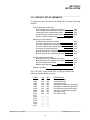
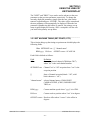
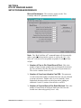
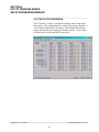
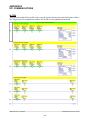
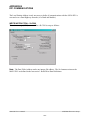
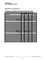
The "CD7TMG" timing channel file, as shipped, contains the
following default timing set-points:
CHAN
CH00:
CH01:
CH02:
CH03:
CH04:
CH05:
CH06:
CH07:
CH10:
CH11:
CH12:
CH13:
CH14:
CH15:
CH16:
CH17:
ON
020
010
180
060
030
250
255
000
000
___
___
___
___
___
___
___
-
OFF
060
050
000
250
200
290
295
140
180
___
___
___
___
___
___
___
HSM-CD7 User’s Manual
DESCRIPTION
Carriage trip timing
Varnish trip timing
Can/No Can clock
Damaged Can Blow-off (Low speed)
Damaged Can Blow-off (High speed)
Pin Chain Blow-off (bad can) timing
Select-A-Can (QC) Blow-off timing
Can Gate Timing
PLC Clock Timing
SYSTEMS Electronics Group
- 19 -
SECTION 2
INSTALLATION
________________________________________________________
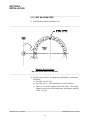
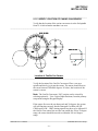
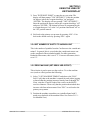
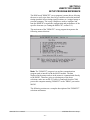
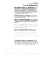
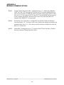
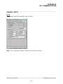
2.11.2 SET MACHINE ZERO
1) Position the machine at machine zero.
________________________________________________________________________________
Machine Zero Position
(as seen from back of machine)
________________________________________________________________________________
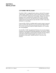
2) Set the resolver offset. Using the Keypad/Display, perform the
following:
a) Press the “Set-Up” key.
b) Press the #5 key – Zero Machine (set resolver offset).
c) Enter “0” to zero the resolver and set the offset. The timing
channel set-up menu will be displayed, showing the position,
“POS:”, at zero.
HSM-CD7 User’s Manual
SYSTEMS Electronics Group
- 20 -
SECTION 2
INSTALLATION
________________________________________________________
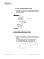
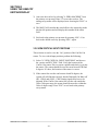
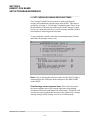
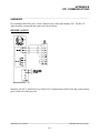
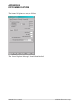
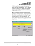
2.11.3 VERIFY LOCATION OF CAN/NO CAN SENSOR
Verify that the location of the can/no can sensor is at the 2nd spindle
from 12 o'clock when the machine is at zero.
________________________________________________________________________________
Location of Can/No Can Sensor
________________________________________________________________________________
Verify the location of the Can/No Can sensor. Place a can on a
spindle and slowly jog it past the sensor. The sensor should first see
the can at between 300 and 0 degrees. If it does, the location of the
sensor is correct.
Note: The Can/No Can sensor “ON” position can be viewed by
selecting option #6 – View Critical Input Positions, from the primary
setup menu using the Keypad/Display.
If the sensor first sees the can between 0 and 30 degrees, the system
will still function correctly but the Damaged Can Blow-off (HI CH04) and (LOW - CH03) timing signals may have to be adjusted. If
the Can/No Can sensor first sees the can outside the 300 to 30 degree
range, the sensor should be moved to within the 300 to 0 degree
range.
HSM-CD7 User’s Manual
SYSTEMS Electronics Group
- 21 -
SECTION 2
INSTALLATION
________________________________________________________
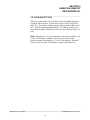
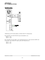
2.11.4 SET PIN CHAIN BLOW-OFF TIMING
1) Set the bad can (pin chain) blow-off timing (CH05) such that the
timing signal just turns “ON” when the pin chain blow-off port is
centered between pins.
________________________________________________________________________________
Location of Blow-off Timing “ON” Position
(channel 05 or 06)
________________________________________________________________________________
2) From the primary setup menu using the Keypad/Display, select
option #3 – Set Machine Timing (set-points, etc.) and perform the
following:
a) With the machine stopped, view the resolver position.
b) Select timing channel CH05 – Pin Chain Blow-off.
c) Clear the channel (press the “CLEAR CHAN” key).
d) Enter a new set-point (press the “ENTER SET-POINT” key).
The “ON” SETPOINT should be the current position of the
resolver (press the “ENTER” key). The “OFF” SETPOINT
should be set 40 degrees after the “ON” set-point (press the
“ENTER” key).
e) Search the channel to confirm only one set-point (one on
setting and one off setting).
HSM-CD7 User’s Manual
SYSTEMS Electronics Group
- 22 -
SECTION 2
INSTALLATION
________________________________________________________
2.11.5 SET # OF PINS TO PIN CHAIN BLOW-OFF PORT
Perform the following to set the "# of pins to pin chain blow-off port":
Note: That the chain take-up must be after the bad can pin chain
blow-off port for reliable pin chain blow-off. If the take-up is before
the port, the relative position of the port to the blow-off timing will
vary as the take-up moves, causing partial blow-offs to occur.
1) Count the number of pins from the spindle wheel to disc transfer
location to the bad can pin chain blow-off port
2) From the primary setup menu using the Keypad/Display, select
option #2 – Set Pin Chain/QC Blow-off Parameters. Press the
“NEXT” key until “# PINS TO PIN CHAIN BLOW-OFF PORT:”
is displayed.
3) The number entered is the number counted minus 2 (this is still
just an approximation).
4) Set the "# CANS TO BLOW-OFF FOR EACH MISLOAD"
(press the “PREV” key) equal to five.
5) Run the machine at low speed. Open the infeed and allow cans to
load and be printed. After cans have passed the pin chain blowoff port, close the infeed and observe the number of cans blown
off.
Note: Half prints or silver cans may get through the line until this
variable is set-up properly.
Adjust the number of pins to pin chain blow-off such that
whenever the infeed is closed, one (half printed) can is
consistently blown off. If no cans are blown off, the number of
pins to pin chain blow-off is too high (blow-off comes on too
late). Reduce the number of pins to pin chain blow-off and repeat
this step again. If more than one can is blown off, the number of
pins is too low (blow-off comes on too early). Increase the
number of pins to pin chain blow-off and repeat this step again.
HSM-CD7 User’s Manual
SYSTEMS Electronics Group
- 23 -
SECTION 2
INSTALLATION
6) Set the "# CANS TO BLOW-OFF FOR EACH MISLOAD" equal
to 3.Run the machine at low speed with cans and verify that for
each miss-loaded can, three bad cans are blown off (miss-loaded
silver can blown off at damaged can blow-off port, half print cans
ahead and behind miss-loaded can blown off at pin chain port). If
not adjust "# of pins to pin chain blow-off port" accordingly until
they are.
Note: Once this variable is set, it may be desirable to set the "# of
cans to blow-off for each misload" equal to 4 or 5 until the print
carriage and varnish unit response times are set in steps 5 and 6. This
is done so that the cans following the miss-load can be verified for
proper print. Once this is done, the "# of cans to blow-off for each
misload" can be set back to 3.
________________________________________________________
2.11.6 SET # OF CANS TO BLOW-OFF AT RESTART
From the primary setup menu using the Keypad/Display, select option
#2 – Set Pin Chain/QC Blow-off Parameters. Set the following infeed
open/restart blow-off parameters (as desired):
a) "# of Cans to Blow-off at Infeed Open"
b) "# of Cans to Blow-off from Print at Restart"
c) "# of Cans to Blow-off from Varnish at Restart”
HSM-CD7 User’s Manual
SYSTEMS Electronics Group
- 24 -
SECTION 2
INSTALLATION
________________________________________________________
2.11.7 SET # OF CANS FROM INFEED TO CAN PRX
This parameter is used to adjust the number of stations from the can
gate solenoid to can/no can sensor. Default value is set to 6 stations.
Some Rutherford decorators utilize an infeed star wheel, adding an
additional 6 (total 12) stations from infeed to can PRX.
Perform the following to set the "# of Cans from Infeed to Can PRX":
1) From the primary setup menu using the Keypad/Display, select
option #2 – Set Pin Chain/QC Blow-off Parameters. Press the
“NEXT” key until “# OF CANS FROM INFEED TO CAN PRX:”
is displayed.
2) Initially set this value to 6. If an infeed star wheel is used, set this
value to 12.
3) Run the machine at low speed. Open the infeed and allow cans to
load and be printed. From the default display of the
Keypad/Display, observe the “BLOWOFFS” field. At “Infeed
Open” this number should increment up by the number of cans to
blow-off at infeed open. Observe that this same number of cans
are blown off at the bad can pin chain blow-off port.
4) If the number of cans blown off was less than the number counted,
increase the number of cans from infeed to can PRX by the
difference.
5) If the number of cans blown off was more than the number
counted, decrease the number of cans from infeed to can PRX by
the difference.
6) Continue to adjust this parameter until the actual number of cans
blown off at infeed open is equal to the desired.
HSM-CD7 User’s Manual
SYSTEMS Electronics Group
- 25 -
SECTION 2
INSTALLATION
________________________________________________________
2.11.8 SET PRINT CARRIAGE AND VARNISH UNIT
"RETRACT"/"EXTEND" RESPONSE TIMES
The retract and extend response times is the amount of time the
control system will lead the trip point (CH00 for the print carriage,
CH01 for the varnish unit) to compensate for the mechanical response
time of the machine. To verify the print carriage and varnish unit trip
control, run the machine at high speed, induce miss-loads and observe
the cans blown off at the pin chain blow-off.
Note: Pressing the “Blank Key” on the Keypad/Display while the
default display is shown will electronically induce a misload into the
system.
The miss-loaded can should be completely silver. The can ahead of
the miss-load (can the carriage retracted on) should be blown off at
the pin chain blow off port and should be 1/4 to 1/2 printed. The can
behind the miss-load (the can the carriage extended on) should be
blown off at the pin chain blow off port and should be 1/2 to 3/4
printed. Any additional cans blown off following the half print behind
the miss-load should be fully printed and of good quality print.
From the primary setup menu using the Keypad/Display, select option
#1 – Set Carriage/Varnish Response Times.
If the can ahead of the miss-load (carriage retracted on) is fully
printed or more than half printed, the "Print Carriage retract (out)
response time" is too short and the carriage is not retracting soon
enough. Increase the "Print Carriage retract (out) response time" by 5
milliseconds and try again. Continue increasing this time until this
can is 1/4 to 1/2 printed. If this can is less than 1/4 printed or silver,
the "Print Carriage retract (out) response time" is too long and the
carriage is retracting too soon. Decrease the "Print Carriage retract
(out) response time" by 5 milliseconds and try again. Continue
decreasing this time until this can is 1/4 to 1/2 printed (press the
“NEXT” key).
HSM-CD7 User’s Manual
SYSTEMS Electronics Group
- 26 -
SECTION 2
INSTALLATION
If the can behind the miss-load (carriage extended on) is less than 1/2
printed or silver, the "Print Carriage extend (in) response time" is too
short and the carriage is not extending soon enough. Increase the
"Print Carriage extend (in) response time" by 5 milliseconds and try
again. Continue increasing this time until this can is 1/2 to 3/4
printed. If this can is more than 3/4 printed or fully printed, the "Print
Carriage extend (in) response time" is too long and the carriage is
extending too soon. Decrease the "Print Carriage extend (in) response
time" by 5 milliseconds and try again. Continue decreasing this time
until this can is 1/2 to 3/4 printed.
Note: The "extend (in)" time is a function of the "retract (out)" time.
Therefore the "retract (out)" time should always be set as desired first,
before setting the "extend (in)" time.
Prior to setting the varnish unit retract/extend response times, set the
number of shifts to the varnish unit. For older generation Rutherford
Decorators, this is set to "5". For newer decorators, this is set to "4".
In general, this is set such that the varnish unit retracts out on the can
ahead of the misloaded spindle.
Set the varnish extend and retract response times in the same fashion
as was done for the carriage. In general, the miss-loaded can should
have no varnish on it, the can ahead and behind should be
approximately 2/3 varnished.
HSM-CD7 User’s Manual
SYSTEMS Electronics Group
- 27 -
SECTION 2
INSTALLATION
________________________________________________________
2.11.9 SET QC BLOW-OFF SHIFT OFFSET
If the QC Can (select-a-can) feature is used, set the "QC can blow-off
port shift offset" as follows:
1) Dial in spindle #1 on the Select-A-Can thumbwheel switch. This
function can also be performed from the Keypad/Display utilizing
the “QC BLOW-OFF” key and entering “1”.
2) With the machine running slowly, mark cans printed on spindle
#1 so they can be identified while on the pin chain.
3) Press the Select-A-Can pushbutton and compare the can that was
actually blown off with the location of a can marked on spindle
#1.
4) From the primary setup menu using the Keypad/Display, select
option #2 – Set Pin Chain/QC Blow-off Parameters. Press the
“NEXT” key until “# QC BLOW-OFF SHIFT OFFSET (1-24):”
is displayed. Add the difference between the can actually blown
off and the marked can on spindle #1 to the QC blow-off shift
offset and enter this as the new offset number.
5) Continue to adjust the offset number until a can marked on
spindle #1 is blown off.
Note: This variable must be a number between 1 and 24 as there is
always a can printed on spindle #1 every 24 cans.
HSM-CD7 User’s Manual
SYSTEMS Electronics Group
- 28 -
SECTION 2
INSTALLATION
________________________________________________________
2.11.10 SET BLANKET WHEEL SEGMENTS
The blanket wheel segments is the value used to blow-off a
consecutive number of cans (starting with blanket #1) whenever a
“Blanket” QC Blow-off is initiated (QC blow-off code #25).
Set the number of “Blanket Wheel Segments” as follows:
1) From the primary setup menu using the Keypad/Display, select
option #2 – Set Pin Chain/QC Blow-off Parameters. Press the
“NEXT” key until “BLANKET WHEEL SEGMENTS (4-12):” is
displayed (last setup parameter in this menu).
2) Enter the number of segments on the blanket wheel.
________________________________________________________
2.11.11 SET SPINDLE TRIP SHIFT OFFSET
Set the "Spindle Trip Shift Offset" as follows:
1) From the primary setup menu using the Keypad/Display, select
option #2 – Set Pin Chain/QC Blow-off Parameters. Press the
“NEXT” key until “SPINDLE TRIP SHIFT OFFSET (0-23):” is
displayed (last setup parameter in this menu).
2) Initially set the "Spindle Trip Offset" to zero.
3) Wrap a piece of tape around spindle #1 such that cans will not
load on this spindle. With the machine running slowly open the
can gate and verify that cans do not load on spindle #1 and that
the print carriage is tripped for that spindle.
4) Observe the “Trips per Spindle” data and determine which spindle
number is being incremented. The spindle number that should be
incrementing is spindle #1. If it is not, subtract 1 from the spindle
number that is being incremented and enter this value as the
“Spindle Trip Shift Offset”.
HSM-CD7 User’s Manual
SYSTEMS Electronics Group
- 29 -
SECTION 2
INSTALLATION
5) Verify that the spindle #1 count is incremented every time the
carriage trips for spindle #1. If it still increments another spindle
number, continue adjusting the "Spindle Trip Shift Offset" until it
does. Stop the machine and remove the tape from spindle #1. The
machine is now set-up and ready to run.
The Machine Is Now Set-Up And Ready To Run!
________________________________________________________
2.12 HSM-CD7 MODULE REPLACEMENT
The following is provided only as a reference. These steps need only
be performed in the event the HSM-CD7 module needs to be replaced
once installed. To replace the module, perform the following:
1) Turn both 115VAC and +24VDC power to the module "off" and
remove all the field wiring connectors from the module.
2) Remove the 8-32 nuts and lock washers (7ea.) which retain the
module in the door and remove the module.
3) Remove the supplied field wiring connectors from the new
module and install the new module in the door cut-out from the
front and re-install the 8-32 nuts and lock washers (7ea).
4) Install the existing pre-wired field wiring connectors on all the I/O
boards of the module (115VAC power connector, I/O slots0 and
1, resolver connector, and IN0/IN1 connector). Make sure all the
field wiring connectors are fully mated in the module.
5) Apply 115VAC and +24VDC power to the module and verify that
the "PWR" and "RUN" LEDs on the module are "on" and the
"FLT" LED is "off".
6) Connect an RS-232 cable from the computer COM port to the
"PROG" port on the HSM-CD7.
7) From the computer's menu program, select the respective
decorator's "SET-UP DECO" selection (this was set in section
2.9). The "HSMCD7" set-up program will be invoked with the
corresponding HSMCD7 application program for that decorator.
HSM-CD7 User’s Manual
SYSTEMS Electronics Group
- 30 -
SECTION 2
INSTALLATION
8) Download the PLS timing set-points to the module by selecting
"3: Machine Timing" from the HSM-CD7 main menu. From the
PLS main development menu, select "4: Download Channels to
PLS". Press the <ENTER> key to start the download. Press any
key to return back to the PLS main development menu. Press
12<ENTER> to return back the HSM-CD7 main menu.
9) Download the previously saved to disk set-up data to the module
by selecting "8: Download Set-up data to Module" from the HSMCD7 main menu. Press the <ENTER> key to start the download.
Once the download is complete, press any key to return to the
HSM-CD7 main menu. See section 5.7 – Download Program to
M4503, for complete details.
10) The HSM-CD7 is now ready to run, loaded with the HSMCD7
timing set-points, and set-up data that was previously saved for
the respective decorator. Press <ESC> to return back to the
computer's menu software program.
HSM-CD7 User’s Manual
SYSTEMS Electronics Group
- 31 -
SECTION 2
INSTALLATION
(This Page Intentionally Left Blank)
HSM-CD7 User’s Manual
SYSTEMS Electronics Group
- 32 -
SECTION 3
USING THE HSM-CD7
KEYPAD/DISPLAY
The keypad/display of the HSM-CD7 contains 24 keys consisting of
12 function keys, and a numeric keypad and a 2 line by 40 character
back-lit LCD display. The keypad/display can be used to view data or
activate the select-a-can QC blow-off to adjust the timing and all setup parameters.
The keypad/display allows the following to be viewed or adjusted:
1) Set Carriage/Varnish Response Times
2) Set Pin Chain/QC Blow-off Parameters
3) Set Machine Timing
4) Set Number of Shifts to Varnish Unit
5) Set Machine Zero
6) View Can/No Can ON Position
7) View the Number of Trips per Spindle
8) View the Shift Data
9) Activate the select-a-can QC blow-off
10) Test Print Carriage and Varnish Unit Trip Control.
Note: For virtually all the menus, the "NEXT" and "PREV" keys can
be used to advance to the next item of the menu or return to the
previous item on the menu.
HSM-CD7 User’s Manual
SYSTEMS Electronics Group
- 33 -
SECTION 3
USING THE HSM-CD7
KEYPAD/DISPLAY
The definitions of the keypad commands and menus are described in
the following sections.
________________________________________________________
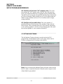
3.1 DEFAULT SCREEN
The default screen (displayed when no other commands are active)
contains the following data:
MACHINE SPEED (CPM):xxxx
GOOD CANS:xxxxxxx
BLOW-OFFS:xxxxxx
Where the "Machine Speed" is the current speed of the decorator, the
"Good Cans" field is the total number of good cans printed so far into
the current shift, and the "Blow-offs" field is the total number of cans
blown-off the machine (scrap) so far into the current shift. This
display effectively replaces a speed meter, and two can counters. This
screen is always returned to when no commands are active.
________________________________________________________
3.2 "TRIPS PER SPINDLE" KEY
The Number of trips per spindle menu is provided to aid in the
trouble-shooting of a loading problem with a spindle or spindles. The
total number of trips for each spindle since the last reset or end of
shift is displayed. The operator can reset these counts at any time to
aid in the trouble-shooting process. The data can be viewed simply be
pressing this key. The display shows a series of screens each with
four spindles from 1 through 24 as shown below:
-- TRIPS (MIS-LOADS) PER SPINDLE -1:xxxx
2:xxxx
3:xxxx
4:xxxx
Where the numbers 1 through 4 are the first 4 spindles and the "xxxx"
would be the actual counts for the respective spindles. Screens for
spindles 5 thru 8, 9 thru 12, etc. are shown in this fashion each for a
time delay of 10 seconds. In addition, the user can advance to the next
screen or retard to the previous screen by pressing the "NEXT" or
"PREV" key respectively.
HSM-CD7 User’s Manual
SYSTEMS Electronics Group
- 34 -
SECTION 3
USING THE HSM-CD7
KEYPAD/DISPLAY
The final screen of this menu, prompts the user to reset the counts by
pressing "0" or not to by pressing "ESC". This provides the operator
with the opportunity to reset the counts if desired for troubleshooting. If the counts are to be reset, press the "0" key, if not, press
the "ESC" key. The default screen will now be displayed again.
The "ESC" key can also be used at any time to abort the trips per
spindle data display and return back to the default screen.
________________________________________________________
3.3 "CURRENT SHIFT" KEY
The Current shift data menu displays the following information:
• Mis-loads:
• Restart Blow-offs:
• Manual Blow-offs:
• QC Blow-offs:
• Trips (Mis-loads) per Spindle (1-24):
Note: The Current shift "Good Cans" and "Blow-offs" are displayed
as part of the default screen
This data is the totals so far into the current shift. This data is
transferred to the "Last shift" data when the end of shift input
transfers from a "0" to a "1". This can be at the end of either an 8 or
12 hour shift or alternatively could be done at label changes such the
data collected would be for label runs rather than complete shifts.
This data cannot be reset by the operator, only at the end of shift input
transition.
Good Cans: This is the total number of good cans printed so far into
the shift. This is essentially a can counter.
Blow-offs: This is the total number of cans blown-off the machine.
This includes all types of blow-offs: the three cans blown-off for
every miss-loaded can, infeed open blow-offs, restart blow-offs,
manual blow-offs, select-a-can QC blow-offs, etc.
Mis-loads: This is the total number of miss-loaded cans (trips).
These would be the actual number of damaged cans that did not load
properly on the machine. This gives an indication of conveying/can
handling problems.
HSM-CD7 User’s Manual
SYSTEMS Electronics Group
- 35 -
SECTION 3
USING THE HSM-CD7
KEYPAD/DISPLAY
Restart Blow-offs: This is the total number of cans blown off when
the infeed opened and from the print station and varnish station at
machine restart.
Manual Blow-offs: This is the total number of cans blown-off by
the operator using the Manual Blow-off PB or selector switch.
QC Blow-offs: This is the total number of cans blown-off by the
operator with the Select-A-Can QC station or QC Blow-off key on the
HSM-CD7 keypad for quality verification.
Trips (Mis-loads) per Spindle (1-24): This is the total trips (misloads) for each spindle. A disproportionately high count for a
particular spindle indicates a loading problem for that spindle.
________________________________________________________
3.4 "LAST SHIFT" KEY
The "Last Shift" data is identical to the current shift data except it is
for the previous 8 or 12 hour shift or previous label run, how ever the
shift collection is set-up. This allows data collection and diagnostics
to take place automatically over a two-shift period. Refer to section
3.3 – “Current Shift” Key, for definitions of the data fields in the
"Last Shift" data menu.
HSM-CD7 User’s Manual
SYSTEMS Electronics Group
- 36 -
SECTION 3
USING THE HSM-CD7
KEYPAD/DISPLAY
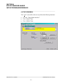
________________________________________________________
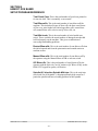
3.5 "SET-UP" KEY
This selection is used to invoke the primary set-up menu. This
consists of the following four selections:
1:
2:
3:
4:
5:
6:
SET CARRIAGE/VARNISH RESPONSE TIMES
SET PIN CHAIN/QC BLOW-OFF PARAMETERS
SET MACHINE TIMING (SET-POINTS, ETC.)
SET NUMBER OF SHIFTS TO VARNISH UNIT
ZERO MACHINE (SET RESOLVER OFFSET)
VIEW CRITICAL INPUT POSITIONS
The set-up menu can be key switch protected such that only
authorized personnel (those with the key) can activate the selection.
The "Set-up Enable" input must be "ON" to invoke the set-up menu.
When selected, each of the above selections will bring up a sub-menu
with the corresponding set-up parameters. The following sections
describe these sub-menus and the definitions of the corresponding
variables. To select the respective set-up sub-menu, simply press the
corresponding numeric key (1 thru 6).
________________________________________________________
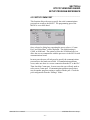
3.5.1 SET CARRIAGE/VARNISH RESPONSE TIMES
This menu is activated when the "1" key (SET CARRIAGE /
VARNISH RESPONSE TIMES) is pressed while the primary set-up
menu is active. See section 2.11.8 for a complete description of how
to adjust the print carriage and varnish unit response times.
The following four set-up parameters may then be adjusted or viewed:
PRINT CARRIAGE RETRACT (OUT) RESPONSE TIME
(msec): This is the time used to lead the trip point to retract the print
carriage (time from solenoid actuation to first break with blanket) in
milliseconds. The M4503 will activate the retract solenoid this
amount of time ahead of the print carriage unit trip timing (CH00)
(usually set at 40 to 50 milliseconds).
HSM-CD7 User’s Manual
SYSTEMS Electronics Group
- 37 -
SECTION 3
USING THE HSM-CD7
KEYPAD/DISPLAY
PRINT CARRIAGE EXTEND (IN) RESPONSE TIME (msec):
This is the time used to lead the trip point to extend the carriage unit
(time from solenoid actuation to first contact with blanket) in
milliseconds. The M4503 will activate the extend solenoid this
amount of time ahead of the print carriage unit trip timing (CH00)
(usually set at 40 to 50 milliseconds).
VARNISH UNIT RETRACT (OUT) RESPONSE TIME (msec):
This is the time used to lead the trip point to retract the varnish unit
(time from solenoid actuation to first break with varnish wheel) in
milliseconds. The M4503 will activate the extend solenoid this
amount of time ahead of the varnish unit trip timing (CH01) (usually
set at 60 milliseconds).
VARNISH UNIT EXTEND (IN) RESPONSE TIME (msec): This
is the time to lead the trip point to extend the varnish unit (time from
solenoid actuation to first contact with varnish wheel) in milliseconds.
The M4503 will activate the extend solenoid this amount of time
ahead of the varnish unit trip timing (CH01) (usually set at 60
milliseconds).
The "NEXT" and "PREV" keys can be used to advance to the next
response time or the previous time respectively. To change the
currently displayed response time, simply enter the new value on the
numeric keypad and press <ENTER>. The value will be entered and
the next response time variable will automatically be displayed. When
the last response time (Varnish extend time) is entered, the primary
set-up menu is again displayed. Pressing <ESC> at anytime will also
exit you back to the primary set-up menu.
Note: All response times entered must be in the range of 5 to 80
milliseconds.
HSM-CD7 User’s Manual
SYSTEMS Electronics Group
- 38 -
SECTION 3
USING THE HSM-CD7
KEYPAD/DISPLAY
________________________________________________________
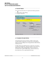
3.5.2 SET PIN CHAIN/QC BLOW-OFF PARAMETERS
This menu is activated when the "2" key (SET PIN CHAIN / QC
BLOW-OFF PARAMETERS) is pressed while the primary set-up
menu is active. The following blow-off set-up parameters may then be
adjusted or viewed:
# CANS TO BLOW-OFF AT INFEED OPEN: This is the number
of cans which will be blown off when the infeed is first opened. Valid
range: 0 to 99.
# TO BLOW-OFF FROM PRINT AT RESTART: This is the
number of cans which will be blown off from the print station when
the machine is restarted. Valid range: 0 to 99.
# CANS TO BLOW-OFF FROM VARNISH AT RESTART: This
is the number of cans which will be blown off from the varnish station
when the machine is restarted. Valid range: 0 to 99.
# CANS TO BLOW-OFF FOR EACH MISLOAD: This is the
number of cans blown off at the pin chain port when one miss-loaded
can is detected (typically set at 3 cans).
# PINS TO PIN CHAIN BLOW-OFF PORT: This is the number of
pins from the spindle wheel to disk transfer location to the first can
blown off at the Pin Chain blow-off port minus two. This can be a
number from 0 to 999.
# OF CANS FROM INFEED TO CAN PRX: This parameter is
used to adjust the number of stations from the can gate solenoid to
can/no can sensor. Default value is set to 6 stations. Some
Rutherford decorators utilize an infeed star wheel, adding an
additional 6 (total 12) stations from infeed to can PRX.
PIN CHAIN (BAD CAN) SOLENOID "ON" RESPONSE TIME
(msec): This is the time used as the "on" response time of the pin
chain blow-off port (time from "on" solenoid actuation to first air out
port) in milliseconds. The M4503 will activate the solenoid this
amount of time ahead of the Pin Chain blow-off timing (CH05)
(usually set at 15 to 20 milliseconds). Valid range: 5 to 60 msec.
HSM-CD7 User’s Manual
SYSTEMS Electronics Group
- 39 -
SECTION 3
USING THE HSM-CD7
KEYPAD/DISPLAY
PIN CHAIN (BAD CAN) SOLENOID "OFF" RESPONSE TIME
(msec): This is the time used as the "off" response time of the pin
chain blow-off port (time from "off" solenoid actuation to air stopping
at port) in milliseconds. The M4503 will activate the solenoid this
amount of time ahead of the Pin Chain blow-off timing (CH05)
(usually set at 15 to 20 milliseconds for double acting solenoids and
set at 25 to 30 milliseconds for single acting solenoids). Valid range:
5 to 60 msec.
QC BLOW-OFF SOLENOID "ON" RESPONSE TIME (msec):
This is the time used as the "on" response time of the QC blow-off
port (time from "on" solenoid actuation to first air out port) in
milliseconds. The M4503 will activate the solenoid this amount of
time ahead of the QC blow-off timing (CH06) (usually set at 15 to 20
milliseconds). Valid range: 5 to 60 msec.
QC BLOW-OFF SOLENOID "OFF" RESPONSE TIME
(msec): This is the time used as the "off" response time of the QC
blow-off port (time from "off" solenoid actuation to air stopping at
port) in milliseconds. The M4503 will activate the solenoid this
amount of time ahead of the QC blow-off timing (CH06) (usually set
at 15 to 20 milliseconds for double acting solenoids and set at 25 to
30 milliseconds for single acting solenoids). Valid range: 5 to 60
msec.
QC BLOW-OFF SHIFT OFFSET: This is the number of spindles
difference from detection of the spindle #1 flag to the QC blow-off
port. This is a number between 1 and 24 and is empirically set by
selecting spindle #1 for blow-off and adjusting this value until the can
from spindle #1 is the can that is blown off.
BLANKET WHEEL SEGMENTS (4-12): The blanket wheel
segments is the value used to blow-off a consecutive number of cans
(starting with blanket #1) whenever a “Blanket” QC Blow-off is
initiated (QC blow-off code #25).
SPINDLE TRIP SHIFT OFFSET: This is the number of spindle
difference from the detection of the spindle #1 flag to the Can/No Can
sensor. This is a number between 0 and 23 and is empirically such
that a miss-loaded can on spindle #1 increments the spindle #1 count
in the "Trips per spindle" menu (see section 2.11.11 – Set Spindle
Trip Shift Offset).
HSM-CD7 User’s Manual
SYSTEMS Electronics Group
- 40 -
SECTION 3
USING THE HSM-CD7
KEYPAD/DISPLAY
The "NEXT" and "PREV" keys can be used to advance to the next
parameter or the previous parameter respectively. To change the
currently displayed parameter, simply enter the new value on the
numeric keypad and press <ENTER>. The value will be entered and
the next parameter will automatically be displayed. When the last
parameter (Spindle trip shift offset) is entered , the primary set-up
menu is again displayed. Pressing <ESC> at anytime will also exit
you back to the primary set-up menu.
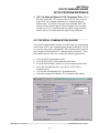
________________________________________________________
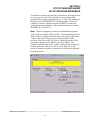
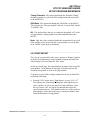
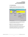
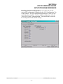
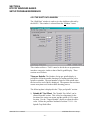
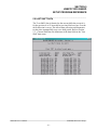
3.5.3 SET MACHINE TIMING (SET-POINTS, ETC.)
This selection brings up the timing set-point menu which displays the
following fields:
CHuu SETPOINT:xxx [] "channel name"
RPM:yyyy POS:zzz OFFSET:wwww SCALE:360
Each field is defined as follows:
Field
CHuu
Definition
Currently selected channel (CH00 thru CH17)
where "uu" is the octal channel number.
SETPOINT:xxx
Channel "on" or "off" set-point where "xxx" is the
set-point position
[]
State of channel set-point (blank = "off", solid
block character = "on")
"channel name"
selected channel name: (CH00) PRINT
CARRIAGE TRIP, (CH01) VARNISH UNIT
TRIP, etc.
RPM:yyyy
Current machine speed where "yyyy" is in CPM.
POS:zzz
Current resolver position where "zzz" is in degrees.
OFFSET:wwww Resolver offset where "wwww" is the offset in
degrees.
HSM-CD7 User’s Manual
SYSTEMS Electronics Group
- 41 -
SECTION 3
USING THE HSM-CD7
KEYPAD/DISPLAY
SCALE:360
Resolver SCALE FACTOR (360 degrees per
revolution).
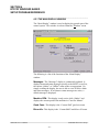
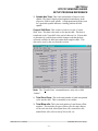
In addition to displaying the timing set-point menu, the following
keys are also enabled: "ENTER SET-POINT", "CLEAR
CHANNEL", "SELECT CHANNEL", and "SEARCH CHANNEL".
The "ENTER SET-POINT" key is used to enter a new set-point (both
"on" and "off" set-points) in the selected channel. The "CLEAR
CHANNEL" key is used to clear all set-points from the selected
channel. The "SELECT CHANNEL" key is used to select a new
channel for programming. The "SEARCH CHANNEL" is used to
view both the "on" and "off" set-points in the selected channel.
Searching Channel: To view the set-points in a channel simply
press the "SEARCH CHANNEL" key. The next "off" to "on" or "on"
to "off" position is shown in the "SETPOINT" field. If the transition
was "off" to "on", the state character [] will be a solid block. If the
transition was "on" to "off", the state character [] will be blank.
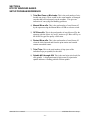
Entering or Adjusting Set-point: To set or adjust a timing
channel, perform the following:
1) Select the channel to be adjusted by pressing the "SELECT
CHANNEL" key, entering the channel number (00 to 17) and
pressing <ENTER>. In addition, the "NEXT" and "PREV" keys
can be used to advance to the next channel or retard to the
previous channel.
2) Press "CLEAR CHANNEL" to clear the existing set-point out.
Note: Entering a new set-point does not automatically clear the
old set-point out. If the two set-points are not in the same place,
the channel will simply have two set-points in it if the old one is
not cleared out first. Therefore always clear the channel before
entering a new set-point. A set-point may, however, be "extended"
by programming another set-point onto an existing set-point using
either the existing "on" or "off" set-point as the starting position
for the new set-point. This will result in one larger set-point.
HSM-CD7 User’s Manual
SYSTEMS Electronics Group
- 42 -
SECTION 3
USING THE HSM-CD7
KEYPAD/DISPLAY
3) Press "ENTER SET-POINT" to enter the new set-point. The
display will then prompt ""ON" SETPOINT:". Enter the position
(in degrees) where the set-point should go "on" and press
<ENTER>. The display will now prompt ""OFF" SETPOINT:".
Enter the position (in degrees) where the set-point should go "off"
and press <ENTER>. The channel will now be programmed with
a set-point that goes "on" at the "on" position entered and "off" at
the "off" position entered.
4) Exit back to the primary set-up menu by pressing <ESC>. Exit
back to the default screen by pressing <ESC> again.
________________________________________________________
3.5.4 SET NUMBER OF SHIFTS TO VARNISH UNIT
This is the number of spindles from the Can Sensor to the varnish unit
minus 2. In general, this is set such that the varnish unit retracts out
on the can ahead of the misloaded spindle. For older generation
Rutherford Decorators, this is set to "5". For newer decorators, this is
set to "4".
________________________________________________________
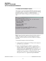
3.5.5 ZERO MACHINE (SET RESOLVER OFFSET)
This selection is used to auto zero the resolver. To set the machine
zero (resolver offset) perform the following:
1) Select "3: SET MACHINE TIMING" and observe the "POS:"
field. Verify that as the machine is rotated forward (either jogging
or barred) that the position increases linearly from 0 through 359.
If not, swap the S1 and S3 leads of the resolver at the M4503
resolver connector. Then verify that the position then indeed does
increase with forward movement. Press "ESC" to exit back to the
primary set-up menu.
2) Position the machine at machine zero (spindle aligned with V
notch at top backside of the machine frame. See section 2.11.2 Set Machine Zero).
HSM-CD7 User’s Manual
SYSTEMS Electronics Group
- 43 -
SECTION 3
USING THE HSM-CD7
KEYPAD/DISPLAY
3) Auto zero the resolver by selecting "4: ZERO MACHINE" from
the primary set-up menu. Enter "0" to zero the resolver. The
timing set-up menu will be displayed, now showing the "POS:" at
zero.
4) The M4503 will calculate the actual offset value required to make
this the 000 position and will display this number in the offset
field.
5) Exit back to the primary set-up menu by pressing <ESC>. Exit
back to the default screen by pressing <ESC> again.
________________________________________________________
3.5.6 VIEW CRITICAL INPUT POSITIONS
This selection is used to view the “On” position of the Can/No Can
sensor. To view critical input positions perform the following:
1) Select "6: VIEW CRITICAL INPUT POSITIONS" and observe
the can/no can PRX "POS:" field. Verify the location of the
Can/No Can sensor. Place a can on a spindle and slowly jog it past
the sensor. The sensor should first see the can at between 300 and
0 degrees. If it does, the location of the sensor is correct.
2) If the sensor first sees the can between 0 and 30 degrees, the
system will still function correctly but the Damaged Can Blow-off
(HI - CH04) and (LOW - CH03) timing signals may have to be
adjusted. If the Can/No Can sensor first sees the can outside the
300 to 30 degree range, the sensor should be moved to within the
300 to 0 degree range. Press "ESC" to exit back to the primary
set-up menu.
HSM-CD7 User’s Manual
SYSTEMS Electronics Group
- 44 -
SECTION 3
USING THE HSM-CD7
KEYPAD/DISPLAY
________________________________________________________
3.6 "QC BLOW-OFF" KEY
This key is used to blow-off a can from a selected spindle at the Pin
Chain QC Blow-off port. To blow-off a can, press the "QC BLOWOFF" key. The display will then prompt "Enter Spindle to Blow Can
off:". Enter the desired spindle number (1-24) and press enter. One
can from that spindle will be blown off at the Pin Chain QC blow-off
port.
Note: Entering in a 25 or 26 will initiate a consecutive can blow-off.
Code 25 will initiate a “Blanket” blow-off (one can from each
blanket, starting with blanket #1). Code 26 will initiate a “Mandrel”
blow-off (one can from each mandrel, starting with mandrel #1).
HSM-CD7 User’s Manual
SYSTEMS Electronics Group
- 45 -
SECTION 3
USING THE HSM-CD7
KEYPAD/DISPLAY
(This Page Intentionally Left Blank)
HSM-CD7 User’s Manual
SYSTEMS Electronics Group
- 46 -
SECTION 4
RTFCD7 WINDOWS BASED
SETUP PROGRAM REFERENCE
The Windows based set-up program is menu driven, allowing the user
to easily view data, alter set-up variables or set machine timing
(machine offset, timing signal locations, etc.), using a PC running the
Windows (95/98/ME/2000/XP/NT) operating system. The set-up
variables are used to configure and tune the M4503 to match the
configuration and performance of the specific decorator (see Tuning
the HSM-CD7, section 2.11).
Note: The set-up program is an on-line communications program
used to interface with the M4503 module. The data displayed and set
in the windows is communicated directly to the module, while in the
“Online” edit mode. Therefore, prior to going online with the
processor, make sure an RS-232 cable is connected from the COM
port on the computer to the "PROG" port on the M4503. The
variables displayed while in the “Online” edit mode are read directly
from the processor. Data is saved to a “Set-up Data” file (*.sdt)
whenever changes are made to a parameter or if the data is uploaded
from the processor.
HSM-CD7 User’s Manual
SYSTEMS Electronics Group
- 47 -
SECTION 4
RTFCD7 WINDOWS BASED
SETUP PROGRAM REFERENCE
________________________________________________________
4.1 GENERAL DESCRIPTION
Title Bar: At the top of the window is the “Title Bar”. The title bar
is used to display the name of the working “Set-up Data” file, as well
as, the name of the active “Window”. The title bar is dark if the
window is active and grayed if another window is active. The color
depends on the settings of the Display Properties of the Control Panel.
Status Bar: At the bottom of the window is the “Status Bar”. The
status bar is used to display system messages, online or offline mode,
as well as, the current time and date as set by the operating system.
The system messages panel displays general information about
operation of the system. The Online/Offline mode panel displays the
status of the current set-up program mode of operation. The mode of
operation can be changed by simply double clicking the online/offline
mode panel.
Hot Keys: Hot keys are activated by holding down the “ALT” key
and simultaneously pressing the underlined letter of the desired
function. Almost every function can be activated by either pressing a
series of hot keys or using the “TAB” key to move between fields.
Online/Offline Modes: The set-up program allows the user to
make changes while “Online” with the processor. The “Offline”
mode is used to preset parameters prior to download. All functions
are available to the user while “Online”, however, specific “Online”
functions are disabled in the “Offline” edit mode.
Note: Offline changes can only be made by enabling “Offline
Editing”, accessed under the “Edit” menu.
Getting Help: The entire contents of the user’s manual is contained
within the help file. Pressing Ctrl+H will display the help file
window. Pressing the F1 key will display the contents file. Hot spots
allow jumps to other topics to display additional information as
desired. Selecting About RTFCD7 from the Help menu will display a
dialog box listing information about the current revision of the setup
program and how to obtain technical support.
HSM-CD7 User’s Manual
SYSTEMS Electronics Group
- 48 -
SECTION 4
RTFCD7 WINDOWS BASED
SETUP PROGRAM REFERENCE
________________________________________________________
4.2 THE FILE MENU
The “File” menu allows the user to perform the following functions:
•
•
•
•
•
•
•
•
Create a “New” set-up “Data File”.
Open an existing “Data File”.
Save any changes made to the current “Data File” to disk.
Upload (save) Data from the Processor.
Download a SYSdev (.sdv) program to the processor
Download (restore) Data from the current set-up “Data File” to
the processor
Print a Report of the current set-up parameters.
Exit the set-up program
HSM-CD7 User’s Manual
SYSTEMS Electronics Group
- 49 -
SECTION 4
RTFCD7 WINDOWS BASED
SETUP PROGRAM REFERENCE
________________________________________________________
4.2.1 THE SET-UP DATA FILE
The set-up “Data File” (.sdt) is a binary access file, designed for fast
file I/O operation. When the set-up program is first invoked, the
default set-up parameters are loaded into memory. If changes are
made to any of the set-up parameters (either online or offline), as well
as shift data, the user will be flagged to “Save Changes” upon exit of
the program.
Note: Any windows based “Set-up” program can open a set-up
“Data File”, however, the data tables will not be properly aligned.
The user will be alerted to the problem if a set-up data file has been
created by either a different set-up program or a different revision of
the software.
The set-up “Data File” is similar to that of a word processing file.
When the program first starts a default file is loaded and the user is
able to make any changes as desired. The set-up program is unaware
of the settings and parameters that exist within the M4503.
Therefore, to normalize the set-up program with the processor, the
user should define or open an existing file, then upload “All”
variables from the processor. This allows the user to either create a
backup of the data or maintain an existing file. The user can even
open a data file for another decorator, save the file to a new name,
make the necessary changes and simply download the new parameters
to another processor.
The following functions can be accessed any time, from any set-up or
display windows.
New: To create a “New” data file, select “New” from the “File”
menu or press “Ctrl + N”. This creates a completely new file, loaded
with the default variables and the word “[unnamed]” is displayed in
the title bar. If any changes were made to the existing file, the user is
prompted to save changes to the existing file.
Open: To “Open” and existing data file, select “Open” from the
“File” menu or press “Ctrl + O”. This displays a dialog box allowing
the user to select an existing data file to open. The name of the file
will be displayed in the title bar. If any changes were made to the
existing file, the user will be prompted to save any changes before
terminating the program.
HSM-CD7 User’s Manual
SYSTEMS Electronics Group
- 50 -
SECTION 4
RTFCD7 WINDOWS BASED
SETUP PROGRAM REFERENCE
Save: To “Save” data file to disk, select “Save” from the “File”
menu or press “Ctrl + S”. This displays a dialog box allowing the
user to select a folder and enter a name for the file. The user will be
notified if the file already exists and the extension “.sdt” will
automatically be added to the file name. If this is a “New” file, the
user will be prompted to enter a file name.
Save As: To save the data file to a new name, select “Save As”
from the “File” menu.. This displays a dialog box allowing the user
to select a folder and enter in a new name for the file. The user will
be notified if the file exists and the extension “.sdt” will automatically
be added to the file name.
Export Shift Data…: This function allows the user to export the
shift data to a “Tab Delimited” text file. This allows the user to easily
use the shift data to produce production reports.
HSM-CD7 User’s Manual
SYSTEMS Electronics Group
- 51 -
SECTION 4
RTFCD7 WINDOWS BASED
SETUP PROGRAM REFERENCE
________________________________________________________
4.2.2 UPLOAD (SAVE) DATA
The “Set-up” program allows the user to upload blow-off parameters,
timing channel set-points and shift data from the M4503 into a set-up
“Data File”. This function is accessed from the “File” menu and the
user is given the choice of the following options:
Set-up Parameters: This option uploads the “Set-up” data from
the M4503. This includes the print carriage and varnish unit response
times, as well as, blow-off parameters.
Timing Channels: This option uploads the “Machine Timing”
channel set-points, as well as, the PLS configuration and scale factor.
Shift Data: This option uploads the “Shift Data” from the M4503.
This includes the “Trips per Spindle” data, the “Current Shift” and the
“Last Shift” data.
All: This option allows the user to completely upload “All” of the
set-up parameters, timing channel set-points and shift data from the
M4503.
HSM-CD7 User’s Manual
SYSTEMS Electronics Group
- 52 -
SECTION 4
RTFCD7 WINDOWS BASED
SETUP PROGRAM REFERENCE
________________________________________________________
4.2.3 DOWNLOAD PROGRAM
The “Set-up” program allows the user to “Download” any SYSdev
program file to the M4503.
Note: To “Download” a SYSdev program to the processor, the
program must be “Online”. If “Online” mode cannot be achieved,
program download will not be executed. If the program is currently
“Offline”, the user will be prompted to first go “Online”.
Once selected, and the set-up program “Online” with the processor, a
dialog box will be displayed, allowing the user to select the SYSdev
file to download.
Note: Only the files with the “.sdv” file extension will be displayed.
It is important to keep in mind that only a valid M4500 PLC SYSdev
file can be downloaded through the set-up program. Care should be
taken when selecting a program to download.
HSM-CD7 User’s Manual
SYSTEMS Electronics Group
- 53 -
SECTION 4
RTFCD7 WINDOWS BASED
SETUP PROGRAM REFERENCE
Once selected, a message box is displayed informing the user of the
current program, revision and checksum of the program loaded in the
processor, as well as, that of the selected program. The user must
confirm their selection by clicking the “Yes” command button. After
the user confirms their choice, program download is initiated and the
current program download address is displayed. When program
download is complete, the user is prompted to acknowledge. Control
is passed back to the main program and the set-up program remains in
an “Online” edit mode.
________________________________________________________
4.2.4 DOWNLOAD (RESTORE) DATA
The set-up program allows the user to download “Set-up”
parameters, timing channel set-points and shift data to the M4503
from the set-up “Data File”. This function is accessed from the “File”
menu and the user is given the choice of the following options:
Set-up Parameters: This option downloads the “Set-up” data to
the M4503. This includes print carriage and varnish unit response
times and blow-off parameters.
HSM-CD7 User’s Manual
SYSTEMS Electronics Group
- 54 -
SECTION 4
RTFCD7 WINDOWS BASED
SETUP PROGRAM REFERENCE
Timing Channels: This option downloads the “Machine Timing”
channel set-points, as well as the PLS configuration and scale factor
to the M4503 PLS.
Shift Data: This option downloads the “Shift Data” to the M4503.
This includes the “Trips per Spindle” data, the “Current Shift” and the
“Last Shift” data.
All: This option allows the user to completely download “All” of the
set-up parameters, timing channel set-points and shift data to the
M4503.
Note: Only the values contained within the current data file are used.
If the validity of the current data file is questionable, review the data
in an “Offline” mode prior to download.
________________________________________________________
4.2.5 PRINT REPORT
The “Set-up” program allows the user to generate a “Report” printout
of all the set-up parameters, timing channel set-points and shift data.
This function is accessed from the “File” menu.
At the top of each page, the report displays the name of the set-up file
being printed. At the bottom of each page is the date and time the
document was printed, as well as, the page number.
To printout a report of the settings contained in the set-up “Data File”,
perform the following:
1) From the “File” menu, select “Print Report” or press “Ctrl + P”.
This displays the “Print Setup” dialog box, allowing the user to
select a printer, as well as, the paper size and orientation. Once
the user selects “OK”, the report is generated and sent to the
specified printer device. This function makes use of the windows
print manager, which allows the user to continue with their work
while the document is being printed.
HSM-CD7 User’s Manual
SYSTEMS Electronics Group
- 55 -
SECTION 4
RTFCD7 WINDOWS BASED
SETUP PROGRAM REFERENCE
________________________________________________________
4.3 THE EDIT MENU
The “Edit” menu allows the user to perform the following functions:
•
•
Enable/Disable Offline Editing.
Set-up the Comm Port.
________________________________________________________
4.3.1 ENABLE OFFLINE EDITING
This function allows the user to perform “Offline” editing on the
currently loaded set-up data file. This allows the user the ability to
make any necessary changes to the set-up parameters while not online
with the processor.
If offline editing is not enabled, the user is only able to view the setup parameters and shift data. When the program is first invoked, the
default setting is offline editing disabled. The user will need to
specifically select “Enable Offline Editing” from the edit menu (or
press function key F2) to enable/disable this feature.
HSM-CD7 User’s Manual
SYSTEMS Electronics Group
- 56 -
SECTION 4
RTFCD7 WINDOWS BASED
SETUP PROGRAM REFERENCE
________________________________________________________
4.3.2 SETUP COMM PORT
This function allows the user to specify the serial communications
port and rate to talk to the M4503. The programming port of the
M4503 is set to 9600 baud.
Once selected, a dialog box requesting the user to select a “Comm
Port” and “Baud Rate” will be displayed. The default setting is
COM1 at 9600 baud. The option to select the 19200 baud rate is to
allow the user to communicate with the processor via the S4516 serial
communications board.
In most cases the user will only need to specify the communications
port and leave the baud rate at 9600. If communication problems
occur, make sure there is a secure connection from the PC to the PLC.
Then check the Comm port. In most cases the user will only need to
select a new Comm port. If communication problems persist there
may be another program causing a conflict with the port. Check the
port configuration from the “Settings” folder.
HSM-CD7 User’s Manual
SYSTEMS Electronics Group
- 57 -
SECTION 4
RTFCD7 WINDOWS BASED
SETUP PROGRAM REFERENCE
________________________________________________________
4.4 THE VIEW MENU
The “View” menu allows the user to perform the following functions:
•
•
•
View the “Target Board Interface”
View “Online” Data
View “Offline” Data
HSM-CD7 User’s Manual
SYSTEMS Electronics Group
- 58 -
SECTION 4
RTFCD7 WINDOWS BASED
SETUP PROGRAM REFERENCE
________________________________________________________
4.4.1 TARGET BOARD INTERFACE
This function allows the user to view fault codes, S3000 network
communication error codes and review the current “Ident” and
“Revision” of the application program. This is accessed by the
“View” menu, by selecting “Target Board Interface”.
Once invoked, the set-up program will prompt the user to select a
program to compare with the one existing in the processor. Whether
a program is selected or the user cancels, the setup program will
attempt to communicate with the M4503. If unsuccessful a warning
message will be displayed, prompting the user to either “Retry” or
“Cancel” the operation. If the operation is canceled and
communication with the processor cannot be established the system
will be placed in an “Offline” mode, however the “Target Board
Interface” window will be displayed.
HSM-CD7 User’s Manual
SYSTEMS Electronics Group
- 59 -
SECTION 4
RTFCD7 WINDOWS BASED
SETUP PROGRAM REFERENCE
________________________________________________________
4.4.2 VIEW ONLINE DATA
This function allows the user to place the set-up program in an
“Online” mode with the processor. This is accessed by the “View”
menu, by selecting “Online Data” or by simply pressing the “F3”
function key.
Note: The program can be toggled between “Offline” and “Online”
by simply double clicking on the “Online” or “Offline” panel
displayed in the status bar at the bottom of the window.
Once invoked, the set-up program will attempt to open the Comm
port and communicate with the M4503. If the set-up program is
unsuccessful, a warning message will be displayed prompting the user
to either “Retry” or “Cancel” the operation. If the operation is
canceled and communication with the processor cannot be established
the system will be placed in an “Offline” edit mode.
Note: Anytime while the set-up program is “Online” with the
processor and communication is interrupted, a warning message will
be displayed, prompting the user to either “Retry” or “Cancel” the
operation.
________________________________________________________
4.4.3 VIEW OFFLINE DATA
This function allows the user to place the set-up program in an
“Offline” mode. This is accessed by the “View” menu, by selecting
“Offline Data” or by simply pressing the “F4” function key. This
allows the user to perform “Offline” editing. All values displayed in
“Offline” edit mode reflect the actual values contained in the
currently loaded set-up data file.
Note: The program can be toggled between “Online” and “Offline”
by simply double clicking on the “Online” or “Offline” panel
displayed in the status bar at the bottom of the window.
Once invoked, the set-up program will close the Comm port and cease
communication with the M4503.
HSM-CD7 User’s Manual
SYSTEMS Electronics Group
- 60 -
SECTION 4
RTFCD7 WINDOWS BASED
SETUP PROGRAM REFERENCE
________________________________________________________
4.5 THE WINDOW MENU
The “Window” menu allows the user to select one of six different
Display/Set-up windows to modify set-up parameters, view shift data
or receive feedback about the current status of the control system.
Once a window menu item is selected, a check mark is placed next to
the selected item and the selected window is displayed and the name
is changed in the title bar of the main window.
Note: “Read” only variables are displayed in blue with a gray
background. Any variables that can be altered by the user are
displayed in black with a white background. In most cases, a
parameter that can be changed by the user will have associated with it
increment and decrement controls. The user can either click on the
desired parameter to adjust and enter in a new value, or use the
increment or decrement controls to change the value by 1 unit.
HSM-CD7 User’s Manual
SYSTEMS Electronics Group
- 61 -
SECTION 4
RTFCD7 WINDOWS BASED
SETUP PROGRAM REFERENCE
________________________________________________________
4.5.1 THE MAIN DISPLAY WINDOW
The “Main Display” window is used to display the general state of the
control system. This window is selected from the “Window” menu.
The following is a list of the functions of the “Main Display”
window.
Messages: The “Messages” display is continuously updated. It
displays alarm and status messages specific to the M4503, as well as,
the current “Online” or “Offline” status of the set-up program. By
simply scrolling the display, the user is able to view all active alarm
and status messages. If no alarm or status messages are active, a
default message is displayed.
Machine CPM: This display is only active while “Online” and
displays the current speed of the machine in “Cans Per Minute”.
Good Cans: This display is the “Current Shift” good can count.
Blow-offs: This display is the “Current Shift” total blow-off count.
HSM-CD7 User’s Manual
SYSTEMS Electronics Group
- 62 -
SECTION 4
RTFCD7 WINDOWS BASED
SETUP PROGRAM REFERENCE
Q.C. Blow-off: This display is only active while “Online” and it
allows the operator to perform a “QC Select-A-Can” blow-off.
The operator can perform a “Single” blow-off by entering in the
desired spindle number and clicking the “Single Blow-off” command
button.
• The operator can perform a “Blanket” blow-off by clicking the
“Blanket Blow-off” command button. The blanket blow-off will
initiate a blow-off sequence such that a can printed by each
blanket is blown off at the QC blow-off port, starting with a can
printed by blanket #1.
• The operator can perform a “Mandrel” Blow-off by clicking the
“Mandrel Blow-off” command button. The mandrel blow-off will
initiate a blow-off sequence such that a can printed on each
mandrel will be consecutively blown off at the QC blow-off port,
starting with mandrel #1.
Bad Can Blow-off: This display is only active while “Online” and
it allows the operator to test the action of the control system by
electronically inducing a mis-loaded or “Bad Can” into the system.
By clicking on the Test Trip/Blow-off command button, a “Bad Can”
will be electronically induced into the system to test the response of
the control system due to a “Mis-Loaded” can.
HSM-CD7 User’s Manual
SYSTEMS Electronics Group
- 63 -
SECTION 4
RTFCD7 WINDOWS BASED
SETUP PROGRAM REFERENCE
________________________________________________________
4.5.2 THE SETUP PARAMETERS WINDOW
The “Set-up Parameters” window is used to view and adjust any of
the set-up parameters. This window is selected from the “Window”
menu.
This window utilizes a “TAB” control to divide the set-up parameters
into three categories, similar to that of the Keypad/Display.
Print Carriage/Varnish Unit: This section is used to set the print
carriage “Retract/Extend” response times and the varnish unit
“Retract/Extend” response times in the M4503. This section contains
the following selections:
1) Print Carriage Retract (out) Response Time (msec): This
is the time used as the retract response time of the carriage unit
(time from solenoid actuation to first break with blanket) in
milliseconds. This will activate the retract solenoid this amount of
time ahead of the Carriage unit trip timing (CH00) (usually set at
40 to 50 milliseconds).
HSM-CD7 User’s Manual
SYSTEMS Electronics Group
- 64 -
SECTION 4
RTFCD7 WINDOWS BASED
SETUP PROGRAM REFERENCE
2) Print Carriage Extend (in) Response Time (msec): This is
the time used as the extend response time of the carriage unit
(time from solenoid actuation to first contact with blanket) in
milliseconds. This will activate the extend solenoid this amount of
time ahead of the Carriage unit trip timing (CH00) (usually set at
40 to 50 milliseconds).
3) Varnish Unit Retract (out) Response Time (msec): This is
the time used as the retract response time of the varnish unit (time
from solenoid actuation to first break with varnish wheel) in
milliseconds. This will activate the extend solenoid this amount of
time ahead of the Varnish unit trip timing (CH01) (usually set at
60 milliseconds).
4) Varnish Unit Extend (in) Response Time (msec): This is
the time used as the extend response time of the varnish unit (time
from solenoid actuation to first contact with varnish wheel) in
milliseconds. This will activate the extend solenoid this amount of
time ahead of the Varnish unit trip timing (CH01) (usually set at
60 milliseconds).
5) Number of Shifts to Varnish Unit: This is the number of
spindles from the Can Sensor to the varnish unit minus 2. In
general this is set such that the varnish unit retracts out on the can
ahead of the misloaded spindle. For older generation Rutherford
Decorators this is set to "5". For newer decorators, this is set to
"4".
HSM-CD7 User’s Manual
SYSTEMS Electronics Group
- 65 -
SECTION 4
RTFCD7 WINDOWS BASED
SETUP PROGRAM REFERENCE
Blow-off Parameters: This section is used to set the “Pin
Chain/QC Blow-off” parameters in the M4503.
Note: The “Bad Can Blow-off” command button will electronically
induce a mis-loaded can into the system, as well as, the “Q.C. Can
Blow-off” will blow-off a can printed on spindle #1 at the QC blowoff port.
1) Number of Pins to Pin Chain Blow-off Port: This is the
number of pins from the spindle wheel to disk transfer location to
the first can blown off at the Pin Chain blow-off port minus two.
This can be a number from 0 to 999.
2) Number of Cans from Infeed to Can PRX: This parameter
is used to adjust the number of stations from the can gate solenoid
to can/no can sensor. Default value is set to 6 stations. Some
Rutherford decorators utilize an infeed star wheel, adding an
additional 6 (total 12) stations from infeed to can PRX.
3) Number of Cans to Blow-off for Each Mis-load: This is the
number of cans blown off at the pin chain port when one misloaded can is detected (typically set at 1 can).
HSM-CD7 User’s Manual
SYSTEMS Electronics Group
- 66 -
SECTION 4
RTFCD7 WINDOWS BASED
SETUP PROGRAM REFERENCE
4) Number of Cans to Blow-off at Infeed Open: This is the
number of cans which will be blown off when the infeed is first
opened. To blow off no cans at infeed open, set equal to 0, to
blow off one can set equal to 1, etc.
5) Number of Cans to Blow-off from Print at Restart: This is
the number of cans which will be blown off from the print station
when the machine is restarted. To blow off no cans at restart, set
equal to 0, to blow off one can set equal to 1, etc.
6) Number of Cans to Blow-off from Varnish at Restart:
This is the number of cans which will be blown off from the
varnish station when the machine is restarted. To blow off no
cans at restart, set equal to 0, to blow off one can set equal to 1,
etc.
7) Q.C. Can Blow-off Port Shift Offset: This is the number of
spindles difference from detection of the spindle #1 flag to the QC
blow-off port. This is a number between 1 and 24 and is
empirically set by selecting spindle #1 for blow-off and adjusting
this value until the can from spindle #1 is the can that is blown
off.
8) Number of Segments on Blanket Wheel: The blanket wheel
segments is the value used to blow-off a consecutive number of
cans (starting with blanket #1) whenever a “Blanket” QC Blowoff is initiated (QC blow-off code #25).
HSM-CD7 User’s Manual
SYSTEMS Electronics Group
- 67 -
SECTION 4
RTFCD7 WINDOWS BASED
SETUP PROGRAM REFERENCE
Blow-off Solenoids: This section is used to adjust the response
times of the “Bad Can” and “QC” blow-off solenoid in the M4503.
1) Bad Can Blow-off Solenoid “ON” Response Time: This is
the time used as the "on" response time of the pin chain blow-off
port (time from "on" solenoid actuation to first air out port) in
milliseconds. The M4503 will activate the solenoid “ON” this
amount of time ahead of the Pin Chain blow-off “ON” position
(usually set at 15 to 20 milliseconds).
2) Bad Can Blow-off Solenoid “Off” Response Time: This is
the time used as the "off" response time of the pin chain blow-off
port (time from "off" solenoid actuation to air stopping at port) in
milliseconds. The M4503 will activate the solenoid “OFF” this
amount of time ahead of the Pin Chain blow-off “ON” position
(usually set at 15 to 20 milliseconds for double acting solenoids
and set at 25 to 30 milliseconds for single acting solenoids).
3) Q.C Can Blow-off Solenoid “ON” Response Time: This is
the time used as the "on" response time of the QC blow-off port
(time from "on" solenoid actuation to first air out port) in
milliseconds. The M4503 will activate the solenoid “ON” this
amount of time ahead of the QC blow-off timing “ON” position
(usually set at 15 to 20 milliseconds).
HSM-CD7 User’s Manual
SYSTEMS Electronics Group
- 68 -
SECTION 4
RTFCD7 WINDOWS BASED
SETUP PROGRAM REFERENCE
4) Q.C. Can Blow-off Solenoid “Off” Response Time: This is
the time used as the "off" response time of the QC blow-off port
(time from "off" solenoid actuation to air stopping at port) in
milliseconds. The M4503 will activate the solenoid “OFF” this
amount of time ahead of the QC blow-off timing “ON” position
(usually set at 15 to 20 milliseconds for double acting solenoids
and set at 25 to 30 milliseconds for single acting solenoids).
________________________________________________________
4.5.3 THE SERIAL COMMUNICATIONS WINDOW
The Serial Communications window is used to view the configuration
status of the S4516 serial communications board (if installed), as well
as, view the status of the Allen-Bradley DF1 communication protocol
and set-up the Allen-Bradley PLC communication parameters. From
this window the user can view or adjust the following parameters:
•
•
•
•
•
•
View the S4516 configuration status.
View the S4516-DF1 serial communication status.
View the Allen-Bradley Link Layer serial communication status.
Select the Allen-Bradley PLC type (PLC5 or SLC500) to
communicate to.
View/Set the Allen-Bradley PLC destination node.
Select the starting Allen-Bradley PLC destination file number.
HSM-CD7 User’s Manual
SYSTEMS Electronics Group
- 69 -
SECTION 4
RTFCD7 WINDOWS BASED
SETUP PROGRAM REFERENCE
S4516 Configuration Status: This displays the current state of
the configuration of the S4516 serial communications board. System
function sfunc19(); (S4516 configuration) is used to set the S4516
configuration (network node address, network baud rate and USER
port baud rate). This must be executed prior to executing ether
system functions 10, 11 or 13. System function 19 is generally
executed in the “Initialization” file of the user program.
The following values are returned from a system function 19 call:
1 = Busy.
2 = Done (S4516 Successfully configured).
3 = Invalid Parameter (either network node address, network
baud rate or USER port baud rate is invalid).
4 = Timeout (no response form S4516)
32 = Hardware ACK error from S4516
34 = Invalid S4516 Slot Address (W8156 must be loaded with
the slot address of the S4516, prior to executing system
function 19).
Transmit Data Status: This represents the state of the data packet
transmission and will typically display either “Busy” or “Done”. If
there are problems delivering the message packet, the response code,
along with a description, will be displayed.
Note: The “Transmit Data Status (prev.)” is used to view the last or
previous status.
Current Transaction: This is the “Transaction” number delivered
to the Allen-Bradley PLC.
Active Command: This displays either “Read” or “Write”. This is
used to view the command type of the current transaction.
Number of BYTES Received: This displays the current number
of bytes received from either a “Command” or “Reply” message
packet.
Received Command BIT Status: This displays the state of the
command received. If this displays a “Reply”, then the command was
sent from the M4503. If this displays “Command”, then a command
action was received by the M4503.
HSM-CD7 User’s Manual
SYSTEMS Electronics Group
- 70 -
SECTION 4
RTFCD7 WINDOWS BASED
SETUP PROGRAM REFERENCE
A/B Link Layer Status: This displays the status of the receipt of
the message packet sent to the Allen-Bradley PLC. If the delivery is
not successful, an error code along with a description is displayed.
Refer the to the Allen-Bradley Communication Protocol and
Command Set reference manual for more information on “Link
Layer” error codes.
A/B Link Layer – Current Transaction Received: This is the
“Transaction” number received from the Allen-Bradley PLC.
PLC Type: This is used to specify the “Type” of PLC the M4503
will communicate to. The user can choose from “PLC5” or
“SLC500”.
Note: This parameter should be set prior to communicating with an
A/B processor.
Destination Node: This is used to set the node number of the A/B
PLC to send and receive data from. This also displays the node
number of the A/B PLC that send a “Command” message packet.
Destination File Number: This is the file number the M4503 will
read and write data from. See Appendix B for a description of the
data read from and written to an Allen-Bradley PLC.
HSM-CD7 User’s Manual
SYSTEMS Electronics Group
- 71 -
SECTION 4
RTFCD7 WINDOWS BASED
SETUP PROGRAM REFERENCE
________________________________________________________
4.5.4 THE MACHINE TIMING WINDOW
The Machine Timing window is used to invoke the PLS programming
command menus. From this window, the user can view or adjust the
following parameters:
•
•
•
•
•
Adjust Timing Channel setpoints.
Set the Main Crank resolver offset.
Clear or Recall a PLS timing channel.
View the current PLS configuration
Reset the PLS configuration to default settings.
In addition, the following parameters are displayed at the bottom of
this window:
RPM: This is the current speed in “Revolutions per Minute” of the
main crank resolver.
Position: This is the current “Position” in degrees of the main crank
resolver.
Offset: This is the current resolver offset (set in degrees).
HSM-CD7 User’s Manual
SYSTEMS Electronics Group
- 72 -
SECTION 4
RTFCD7 WINDOWS BASED
SETUP PROGRAM REFERENCE
Scale: This is the scale factor of the resolver or the number of
divisions in one revolution.
Note: The General Timing Signal Locations section provides a
complete description of each timing channel signal.
Zeroing the Machine (setting the resolver offset): To set
machine zero, perform the following:
1) Connect an RS-232 SYSdev cable from the COM port on the
computer to the “PROG” port on the M4503.
2) From the “Window” menu, select “Machine Timing”.
3) From the “View” menu, select “Online Data”. The set-up
program will attempt to communicate with the processor and
place the system into an “Online” mode of operation.
4) Observe the “Position” field at the bottom of the window. Verify
that as the machine is rotated forward, that the position increases
linearly from 0 through 359 degrees. If not, swap the S1 and S3
leads at the resolver connector on the M4503. Then, verify that
the position does indeed increase with forward movement.
5) Position the machine at machine zero (spindle aligned with V
notch at top backside of machine frame, see section 2.11.2 - Set
Machine Zero).
6) Auto zero the resolver by entering “0” in the “Resolver Offset”
field and clicking the “Set Offset” command button. A message
box will appear, prompting the user to confirm their choice.
Select “Yes” to set the resolver offset.
7) The M4503 will calculate the actual offset value required to make
this the “0” position. The new offset value will be displayed in
the “Offset” field and the position will then read zero.
HSM-CD7 User’s Manual
SYSTEMS Electronics Group
- 73 -
SECTION 4
RTFCD7 WINDOWS BASED
SETUP PROGRAM REFERENCE
Adjusting the Timing Channel Setpoints: To set any of the
timing signal setpoints, perform the following:
Note: Any changes made to the timing channel setpoints will be
saved as part of the setup data file.
1) Connect an RS-232 SYSdev cable from the COM port on the
computer to the “PROG” port on the M4510.
2) From the “Window” menu, select “Machine Timing”.
3) From the “View” menu, select “Online Data”. The set-up
program will attempt to communicate with the processor and
place the system into an “Online” mode of operation.
4) Set all channels per the section 6 – General Timing Signal
Locations. Set-points for a particular channel are either entered in
the field or adjusted by using the increment/decrement controls.
Note: Only one set-point is used per channel.
5) If a channel needs to be “Recalled” or “Cleared”, enter the desired
channel number into the “PLS Channel” field. Click the “Recall
Channel” command button to recall the setpoints. Click the
“Clear Channel” command button the completely clear all
setpoints for the selected channel.
Note: If a channel has been cleared or the “On” and “Off”
setpoints have the same setting, the set-point will be displayed as
“*****”.
HSM-CD7 User’s Manual
SYSTEMS Electronics Group
- 74 -
SECTION 4
RTFCD7 WINDOWS BASED
SETUP PROGRAM REFERENCE
Resetting the PLS Configuration: As an aid to the user the
current PLS configuration is displayed in the “PLS Configuration” tab
of this window. The PLS configuration should only be reset if a new
module has been installed. To reset the PLS configuration, click the
“Reset PLS Config” command button. This function only resets the
PLS configuration to the default settings.
HSM-CD7 User’s Manual
SYSTEMS Electronics Group
- 75 -
SECTION 4
RTFCD7 WINDOWS BASED
SETUP PROGRAM REFERENCE
________________________________________________________
4.5.5 THE SHIFT DATA WINDOW
The “Shift Data” window is used to view the shift data collected by
the M4503. This window is selected from the “Window” menu.
This window utilizes a “TAB” control to divide the set-up parameters
into three categories, similar to that of the Keypad/Display. These
sections are as follows:
Trips per Spindle: The Number of trips per spindle display is
provided to aid in the trouble-shooting of a loading problem with a
spindle or spindles. The total number of trips for each spindle since
the last reset or end of shift is displayed. The operator can reset these
counts at anytime to aid in the trouble-shooting process.
The following data is displayed in the "Trips per Spindle" section:
1) Spindle #1 Trip Offset: The "Spindle Trip Offset" can be
entered from this section. This is used to compensate for the
location of the can/no can sensor and the spindle #1 I.D. sensor
location. Use the “Tripped Spindle” display to adjust the offset
value. Follow the procedure outlined in section 2.11.11 – Set
Spindle Trip Shift Offset.
HSM-CD7 User’s Manual
SYSTEMS Electronics Group
- 76 -
SECTION 4
RTFCD7 WINDOWS BASED
SETUP PROGRAM REFERENCE
2) Spindle #xx Trips: This is the total number of trips for each
spindle. This data is displayed and updated continuously in the
respective field for each spindle. A disproportionately high count
for a particular spindle indicates a loading problem for that
spindle.
Current Shift Data: This section is used to view the “Current
Shift” data. This data is the totals so far into the shift. This data is
transferred to the "Last shift" at the end of either an 8 or 12 hour shift
or alternatively could be done at label changes such that the data
collected would be for label runs rather than complete shifts. This
data can be reset by the user from this section.
Note: The “Transfer Data” command button is only active while
“Online”.
1) Total Good Cans: This is the total number of good cans printed
so far into the shift. This is essentially a can counter.
2) Total Blow-offs: This is the total number of cans blown-off the
machine. This includes all types of blow-offs: the can(s) blownoff for each mis-load, infeed open blow-offs, restart blow-offs,
manual blow-offs, select-a-can QC blow-offs, etc.
HSM-CD7 User’s Manual
SYSTEMS Electronics Group
- 77 -
SECTION 4
RTFCD7 WINDOWS BASED
SETUP PROGRAM REFERENCE
3) Total Bad Cans or Mis-loads: This is the total number of misloaded cans (trips). These would be the actual number of damaged
cans that did not load properly on the machine. This gives an
indication of conveying/can handling problems.
4) Manual Blow-offs: This is the total number of cans blown-off
by the operator using the Manual Blow-off PB or selector switch.
5) QC Blow-offs: This is the total number of cans blown-off by the
operator with the Select-A-Can QC station or QC Blow-off key on
the M4503 keypad for quality verification.
6) Restart Blow-offs: This is the total number of cans blown off
when the infeed opened and from the print station and varnish
station at machine restart.
7) Total Trips: This is the total number of trips (sum of the
individual trips per spindle) for the shift.
8) Spindle #01 through #24: This is the total trips (mis-loads) for
each spindle. A disproportionately high count for a particular
spindle indicates a loading problem for that spindle.
HSM-CD7 User’s Manual
SYSTEMS Electronics Group
- 78 -
SECTION 4
RTFCD7 WINDOWS BASED
SETUP PROGRAM REFERENCE
Last Shift Data: The "Last Shift" data is identical to the current
shift data except it is for the previous 8 or 12 hour shift or previous
label run, however the shift collection is set-up. This allows data
collection and diagnostics to take place automatically over a two shift
period.
HSM-CD7 User’s Manual
SYSTEMS Electronics Group
- 79 -
SECTION 4
RTFCD7 WINDOWS BASED
SETUP PROGRAM REFERENCE
________________________________________________________
4.5.6 THE I/O STATES WINDOW
The “I/O States” window is provided to display states of the inputs
and outputs. The control boards, the states of the timing channels, as
well as states of the M4503 are shown. This includes the interrupt
inputs (IN0 and IN1), the analog I/O and the resolver. These values
are displayed as read by the M4503 processor.
HSM-CD7 User’s Manual
SYSTEMS Electronics Group
- 80 -
SECTION 5
HSMCD7 DOS BASED
SETUP PROGRAM REFERENCE
The DOS based "HSMCD7" set-up program is menu driven, allowing
the user to easily view data, alter set-up variables and set the machine
timing (machine offset, timing signal locations, etc.) using a laptop or
personal computer. The set-up variables are used to configure and
tune the HSMCD7 to match the configuration and performance of the
specific decorator (see Tuning the HSM-CD7, section 2.11).
The main menu of the "HSMCD7" set-up program incorporates the
following menu selections:
Note: The "HSMCD7" program is an on-line communications
program used to interface with the M4503 module. The data
displayed in the menus and set in the menus is communicated directly
to the M4503. Therefore, prior to selecting any of the above
selections, make sure an RS-232 cable is connected from the COM
port on the computer running "HSMCD7" to the "PROG" port on the
M4503.
The following sections are a complete description of the "HSMCD7"
selections and menus.
HSM-CD7 User’s Manual
SYSTEMS Electronics Group
- 81 -
SECTION 5
HSMCD7 DOS BASED
SETUP PROGRAM REFERENCE
________________________________________________________
5.1 SET CARRIAGE/VARNISH RESPONSE TIMES
The Carriage/Varnish Unit set-up menu is used to set the print
carriage and varnish unit response times in the M4503. This menu is
invoked by selecting "1: Set Carriage/Varnish Response Times" from
the Main Menu. The menu selections on the "Print Carriage/Varnish
Unit set-up" menu allow the user to set the Carriage/Varnish variables
listed under the following menu selections:
To set a particular variable, select the corresponding menu selection
and follow the prompts as they occur.
Note: Prior to selecting this selection, make sure the RS-232 cable is
connected from the COM port on the computer to the PROG PORT
on the M4503.
Print Carriage retract response time: This is the time used as
the retract response time of the carriage unit (time from solenoid
actuation to first break with blanket) in milliseconds. The M4503 will
activate the retract solenoid this amount of time ahead of the Carriage
unit trip timing (CH00) (usually set at 40 to 50 milliseconds).
HSM-CD7 User’s Manual
SYSTEMS Electronics Group
- 82 -
SECTION 5
HSMCD7 DOS BASED
SETUP PROGRAM REFERENCE
Print Carriage extend response time: This is the time used as
the extend response time of the carriage unit (time from solenoid
actuation to first contact with blanket) in milliseconds. The M4503
will activate the extend solenoid this amount of time ahead of the
Carriage unit trip timing (CH00) (usually set at 40 to 50
milliseconds).
Varnish Unit retract response time: This is the time used as the
retract response time of the varnish unit (time from solenoid actuation
to first break with varnish wheel) in milliseconds. The M4503 will
activate the extend solenoid this amount of time ahead of the Varnish
unit trip timing (CH01) (usually set at 60 milliseconds).
Varnish Unit extend response time: This is the time used as the
extend response time of the varnish unit (time from solenoid actuation
to first contact with varnish wheel) in milliseconds. The M4503 will
activate the extend solenoid this amount of time ahead of the Varnish
unit trip timing (CH01) (usually set at 60 milliseconds).
Number of Shifts to Varnish Unit: This is the number of spindles
from the Can Sensor to the varnish unit minus 2. In general, this is set
such that the varnish unit retracts out on the can ahead of the
misloaded spindle. For older generation Rutherford Decorators, this is
set to "5". For newer generation decorators, this is set to "4".
HSM-CD7 User’s Manual
SYSTEMS Electronics Group
- 83 -
SECTION 5
HSMCD7 DOS BASED
SETUP PROGRAM REFERENCE
________________________________________________________
5.2 SET PIN CHAIN/QC BLOW-OFF PARAMETERS
The Pin Chain/QC Can Blow-off set-up menu is used to set the Pin
Chain/QC Blow-off parameters in the M4503. This menu is invoked
by selecting "2: Set Pin Chain/QC Blow-off Parameters" from the
Main Menu. The menu selections on the "Pin Chain/QC blow-off setup" menu allow the user to set the Pin Chain/QC Blow-off variables
listed under the following menu selections:
To set a particular variable, select the corresponding menu selection
and follow the prompts as they occur.
Note: Prior to selecting this selection, make sure the RS-232 cable is
connected from the COM port on the computer to the PROG PORT
on the M4503.
Bad Can Blow-off solenoid "on" response time: This is the
time used as the "on" response time of the pin chain blow-off port
(time from "on" solenoid actuation to first air out port) in
milliseconds. The M4503 will activate the solenoid this amount of
time ahead of the Pin Chain blow-off timing (CH05) (usually set at 15
to 20 milliseconds).
HSM-CD7 User’s Manual
SYSTEMS Electronics Group
- 84 -
SECTION 5
HSMCD7 DOS BASED
SETUP PROGRAM REFERENCE
Bad Can Blow-off solenoid "off" response time: This is the
time used as the "off" response time of the pin chain blow-off port
(time from "off" solenoid actuation to air stopping at port) in
milliseconds. The M4503 will activate the solenoid this amount of
time ahead of the Pin Chain blow-off timing (CH05) (usually set at 15
to 20 milliseconds for double acting solenoids and set at 25 to 30
milliseconds for single acting solenoids).
# of bad cans to blow-off for misload: This is the number of
cans blown off at the pin chain port when one miss-loaded can is
detected (typically set at 3 cans).
# of cans to blow-off from infeed open: This is the number of
cans which will be blown off when the infeed is first opened. To blow
off no cans at infeed open, set equal to 0, to blow off one can set
equal to 1, etc.
# of cans to blow-off from print at restart: This is the number
of cans which will be blown off from the print station when the
machine is restarted. To blow off no cans at restart, set equal to 0, to
blow off one can set equal to 1, etc.
# of cans to blow-off from varnish at restart: This is the
number of cans which will be blown off from the varnish station
when the machine is restarted. To blow off no cans at restart, set
equal to 0, to blow off one can set equal to 1, etc.
# of pins to pin chain blow-off port: This is the number of pins
from the spindle wheel to disk transfer location to the first can blown
off at the Pin Chain blow-off port minus two. This can be a number
from 0 to 999.
QC Can Blow-off solenoid "on" response time: This is the
time used as the "on" response time of the QC blow-off port (time
from "on" solenoid actuation to first air out port) in milliseconds. The
M4503 will activate the solenoid this amount of time ahead of the QC
blow-off timing (CH06) (usually set at 15 to 20 milliseconds).
HSM-CD7 User’s Manual
SYSTEMS Electronics Group
- 85 -
SECTION 5
HSMCD7 DOS BASED
SETUP PROGRAM REFERENCE
QC Can Blow-off solenoid "off" response time: This is the
time used as the "off" response time of the QC blow-off port (time
from "off" solenoid actuation to air stopping at port) in milliseconds.
The M4503 will activate the solenoid this amount of time ahead of the
QC blow-off timing (CH06) (usually set at 15 to 20 milliseconds for
double acting solenoids and set at 25 to 30 milliseconds for single
acting solenoids).
QC Can Blow-off port shift offset: This is the number of
spindles difference from detection of the spindle #1 flag to the QC
blow-off port. This is a number between 1 and 24 and is empirically
set by selecting spindle #1 for blow-off and adjusting this value until
the can from spindle #1 is the can that is blown off.
________________________________________________________
5.3 SET MACHINE TIMING
The Set Machine Timing selection is used to invoke the PLS
programming command menus (these are the same menus used in
SYSdev to program the PLS section of the M4503).
Note: Prior to selecting the Machine Timing selection, make sure the
RS-232 cable is connected from the COM port on the computer to the
CHAN PORT on the M4503.
HSM-CD7 User’s Manual
SYSTEMS Electronics Group
- 86 -
SECTION 5
HSMCD7 DOS BASED
SETUP PROGRAM REFERENCE
When selected, the PLS programming main development menu will
be invoked using the default CD7TMG channel set-point file .
From this menu, the user can zero the machine (set the resolver
offset) and adjust the timing signal set-points.
Note: Section 6 provides a complete description of each timing
signal.
HSM-CD7 User’s Manual
SYSTEMS Electronics Group
- 87 -
SECTION 5
HSMCD7 DOS BASED
SETUP PROGRAM REFERENCE
________________________________________________________
5.3.1 ZEROING THE MACHINE
To set the machine zero (resolver offset) perform the following:
1) Connect the RS-232 cable from the COM port on the computer to
the "PROG" port on the M4503.
2) Select the "3: Set Machine Timing" selection from the HSM-CD7
set-up program main menu.
3) Select "1: Online Channel Setpoint Programming" from the Main
Development menu.
4) Select "F9: POS/RPM" and observe the "POS:" field. Verify that
as the machine is rotated forward (either jogging or barred) that
the position increases linearly from 0 through 359. If not, swap
the S1 and S3 leads of the resolver at the M4503 resolver
connector. Then verify that the position then indeed does increase
with forward movement. Press "ESC" to exit the "POS/RPM"
update.
5) Position the machine at machine zero (spindle aligned with V
notch at top backside of machine frame, see section 2.11.2 – Set
Machine Zero).
6) Auto zero the resolver by selecting "F10: Set Offset". Enter "0" in
the offset field and press <ENTER>.
7) The M4503 will calculate the actual offset value required to make
this the 000 position and will display this number in the offset
field. The position will now read 0.
8) Exit back to the PLS Main Development menu by pressing
<ESC>. Exit back to the "HSMCD7" set-up main menu by
pressing <ESC> again.
HSM-CD7 User’s Manual
SYSTEMS Electronics Group
- 88 -
SECTION 5
HSMCD7 DOS BASED
SETUP PROGRAM REFERENCE
________________________________________________________
5.3.2 ADJUSTING THE TIMING CHANNEL SET-POINTS
To set or alter any of the timing signal set-points, perform the
following:
1) Connect the RS-232 cable from the COM port on the computer to
the "PROG" port on the M4503.
2) Select the "3: Set Machine Timing" selection from the HSM-CD7
set-up program main menu.
3) Select "1: Online Channel Setpoint Programming" from the Main
Development menu.
4) Set all channels per section 6. Set-points are entered for a
particular channel simply by typing in the set-point in the form
XXX-YYY<ENTER> in the first set-point of the given channel.
Note: Up to 50 set-points may be entered for any channel.
However, for the decorator, only one set-point is used per channel
and should be entered in the number 1 set-point.
The XXX is the location the set-point will turn "on" while YYY is
the location where the set-point will turn "off". Use the PgUp,
PgDn, F1:Next Chan, or F2: Prev Chan keys to select the desired
channel for programming.
5) Once all channels are programmed, press <ESC> to exit back to
the PLS Main Development Menu. Press <ESC> again to exit
back to the "HSMCD7" set-up main menu. The new channels will
be saved both in the M4503 and in the "CD7TMG" file on the
hard drive.
HSM-CD7 User’s Manual
SYSTEMS Electronics Group
- 89 -
SECTION 5
HSMCD7 DOS BASED
SETUP PROGRAM REFERENCE
________________________________________________________
5.4 NUMBER OF TRIPS PER SPINDLE DATA
The Number of trips per spindle menu is provided to aid in the
trouble-shooting of a loading problem with a spindle or spindles. The
total number of trips for each spindle since the last reset or end of
shift is displayed. The operator can reset these counts at any time to
aid in the trouble-shooting process. In addition, the "Spindle Trip
Offset" can be entered from this menu. This is used to compensate for
the location of the can/no can sensor and the spindle #1 I.D. sensor
location.
When the "4: Number of Trips per Spindle" selection is selected from
the main menu, the total trips per spindle is displayed and updated
continuously in fields that read "Spindle #xx trips:" for each spindle.
To exit back to the main menu, press <ESC>. A disproportionately
high count for a particular spindle indicates a loading problem for that
spindle.
Note: Prior to selecting this selection, make sure the RS-232 cable is
connected from the COM port on the computer to the "PROG" port
on the M4503.
HSM-CD7 User’s Manual
SYSTEMS Electronics Group
- 90 -
SECTION 5
HSMCD7 DOS BASED
SETUP PROGRAM REFERENCE
The menu selections on the "Trips Per Spindle" menu allow you to
reset the trips per spindle counts or set the "Spindle Trip Shift Offset.
The selections are listed below:
1: Set Spindle #1 trip offset
2: Reset Spindle trip counts
To set the spindle trip offset, select "1" and enter the required offset
(see section 2.11.11 – Set Spindle Trip Shift Offset) and press
<ENTER>. To reset the spindle trip counts, simply press "2". The
counts will be reset in the M4503. To exit back to the main menu,
press <ESC>.
________________________________________________________
5.5 CURRENT SHIFT DATA
The Current shift data menu displays the following information:
This data is the totals so far into the shift. This data is transferred to
the "Last shift" data when the end of shift input transfers from a "0" to
a "1". This can be at the end of either an 8 or 12 hour shift or
alternatively could be done at label changes such that the data
collected would be for label runs rather than complete shifts. This
data cannot be reset either from this menu or by the operator, only at
the end of shift input transition. To exit back to the main menu, press
<ESC>.
HSM-CD7 User’s Manual
SYSTEMS Electronics Group
- 91 -
SECTION 5
HSMCD7 DOS BASED
SETUP PROGRAM REFERENCE
Total Good Cans: This is the total number of good cans printed so
far into the shift. This is essentially a can counter.
Total Blow-offs: This is the total number of cans blown-off the
machine. This includes all types of blow-offs: the three cans blownoff for every miss-loaded can, infeed open blow-offs, restart blowoffs, manual blow-offs, select-a-can QC blow-offs, etc.
Total Mis-loads: This is the total number of miss-loaded cans
(trips). These would be the actual number of damaged cans that did
not load properly on the machine. This gives an indication of
conveying/can handling problems.
Restart Blow-offs: This is the total number of cans blown off when
the infeed opened and from the print station and varnish station at
machine restart.
Manual Blow-offs: This is the total number of cans blown-off by
the operator using the Manual Blow-off PB or selector switch.
QC Blow-offs: This is the total number of cans blown-off by the
operator with the Select-A-Can QC station or QC Blow-off key on the
HSM-CD7 keypad for quality verification.
Spindle #01 trips thru Spindle #24 trips: This is the total trips
(mis-loads) for each spindle. A disproportionately high count for a
particular spindle indicates a loading problem for that spindle.
HSM-CD7 User’s Manual
SYSTEMS Electronics Group
- 92 -
SECTION 5
HSMCD7 DOS BASED
SETUP PROGRAM REFERENCE
________________________________________________________
5.6 LAST SHIFT DATA
The "Last Shift" data is identical to the current shift data except it is
for the previous 8 or 12 hour shift or previous label run, how ever the
shift collection is set-up. This allows data collection and diagnostics
to take place automatically over a two shift period. Refer to section
5.5 – Current Shift Data for definitions of the data fields in the "Last
Shift" data menu.
HSM-CD7 User’s Manual
SYSTEMS Electronics Group
- 93 -
SECTION 5
HSMCD7 DOS BASED
SETUP PROGRAM REFERENCE
________________________________________________________
5.7 DOWNLOAD PROGRAM TO M4503
This selection is used to download the HSMCD7 application program
to the M4503 module. This should only be performed when replacing
the M4503 module (see section 2.12 – HSM-CD7 Module
Replacement) or whenever changes have been made to the source
code.
Note: Program download cannot be performed while the machine is
running. All outputs are turned "off" and no program execution is
performed. Any miss-loaded cans will not be tripped for resulting in
inside litho.
To download the program, perform the following:
1) Connect the RS-232 cable from the COM port on the computer to
the "PROG" port on the M4503.
2) Select "7: Download Program to M4503". A prompt will be
displayed asking to continue or abort. To continue, press any key
except the <ESC> key. To abort, press the <ESC> key. If a
prompt stating that the "HSMCD7.REV" file could not be opened
is displayed, then the "HSMCD7" application program is not
installed in the current directory. To install the program, perform
the steps in section 2.9.4 – Application Program Installation.
HSM-CD7 User’s Manual
SYSTEMS Electronics Group
- 94 -
SECTION 5
HSMCD7 DOS BASED
SETUP PROGRAM REFERENCE
3) Once program download is initiated, M4503 program execution
will cease, the current address being downloaded will be
displayed, and the "RUN" LED on the M4503 will flash
continuously.
4) Once the download is complete, the "RUN" LED on the M4503
will illuminate solid and program execution in the M4503 will
resume. Press any key to return back to the "HSMCD7" main
menu.
________________________________________________________
5.8 DOWNLOAD SET-UP DATA TO M4503
This selection is used to download the previously uploaded (saved)
set-up variables to the M4503. This should only be performed when
replacing the M4503 module (see section 2.12 – HSM-CD7 Module
Replacement).
Note: The set-up data consists of the carriage/varnish response times,
pin chain/QC blow-off parameters and the spindle trip shift offset.
Timing channel set-points are not stored as part of the set-up data. To
download the set-up data, perform the following:
1) Connect the RS-232 cable from the COM port on the computer to
the "PROG" port on the M4503.
2) Select "8: Download Set-up data to M4503". A prompt will be
displayed asking to continue or abort. To continue, press any key
except the <ESC> key. To abort, press the <ESC> key.
3) Once data download is initiated, the current address being
downloaded will be displayed.
Note: Program execution is not ceased, therefore data download
can be performed while the machine is running.
4) Once set-up data download is complete, press any key to return to
the "HSMCD7" main menu.
HSM-CD7 User’s Manual
SYSTEMS Electronics Group
- 95 -
SECTION 5
HSMCD7 DOS BASED
SETUP PROGRAM REFERENCE
________________________________________________________
5.9 UPLOAD (SAVE) SET-UP DATA FROM M4503
This selection is used to save the set-up variables from the M4503 to
the hard drive (current directory selected). This should be performed
anytime any of the set-up variables have been changed.
Note: When the set-up variables are changed, they are changed
directly in the M4503, not on the file in the computer. By uploading
(saving) the set-up variables to disk, they can be downloaded to the
M4503 in the event the module must be replaced. The set-up data
consists of the carriage/varnish response times, pin chain/QC blowoff parameters and the spindle trip shift offset. Timing channel setpoints are not stored as part of the set-up data. To upload the set-up
data, perform the following:
1) Connect the RS-232 cable from the COM port on the computer to
the "PROG" port on the M4503.
2) Select "9: Upload (Save) Set-up data from M4503". A prompt will
be displayed asking to continue or abort. To continue, press any
key except the <ESC> key. To abort, press the <ESC> key.
3) Once data upload is initiated, the current address being uploaded
will be displayed.
Note: Program execution is not ceased, therefore data upload can
be performed while the machine is running.
4) Once set-up data upload is complete, press any key to return to the
"HSMCD7" main menu.
HSM-CD7 User’s Manual
SYSTEMS Electronics Group
- 96 -
SECTION 6
GENERAL TIMING SIGNAL LOCATIONS
The following is a general description of the timing signals and the
locations they should be set at:
CH00: PRINT CARRIAGE TRIP: This signal should just turn
"on" when a spindle is at the midpoint of a blanket. For a
bad can, the carriage is retracted midway of the can previous
to the bad can and extended midway on the can following
the bad can. This signal should be 40 degrees wide.
Location of Print Carriage Trip Timing
(CH00 – ON Set-point)
HSM-CD7 User’s Manual
SYSTEMS Electronics Group
- 97 -
SECTION 6
GENERAL TIMING SIGNAL LOCATIONS
CH01: VARNISH UNIT TRIP: This signal should just turn "on"
when a spindle is centered on the varnish wheel. For a bad
can, the varnish unit is retracted midway on the can previous
to the bad can and extended midway on the can following
the bad can. This signal should be 40 degrees wide.
Location of Varnish Unit Trip Timing
(CH01 – ON Set-point)
CH02: CAN/NO CAN CLOCK: This signal is used to clock the
bad can shift register which activates the carriage, varnish,
and pin chain blow-off for miss-loaded cans. It is also used
as a general purpose clock for all shift registers, counters,
etc. The can/no can clock is generally set "on" at 180
degrees and "off" at 000 degrees. The "off" to "on" transition
of CH02 cannot however coincide with either the CH00
(Carriage trip), CH01 (Varnish trip), or CH05 (Pin Chain
Blow-off) timing signals. These timing signals must be set at
least 30 degrees ahead or behind the CH02 "off" to "on"
transition.
CH03: DAMAGED CAN BLOW-OFF (LO) TIMING: This signal
is used to activate the damaged can blow-off solenoid at low
speeds (below 1000CPM). The damaged can blow-off "on"
solenoid will actually be "on" for the duration of CH03
when a miss-loaded can is detected. This signal should be
set "on" 10 degrees before air starts to leave the damaged
can port and set "off" 20 degrees before air stops leaving the
port.
HSM-CD7 User’s Manual
SYSTEMS Electronics Group
- 98 -
SECTION 6
GENERAL TIMING SIGNAL LOCATIONS
CH04: DAMAGED CAN BLOW-OFF (HI) TIMING: This signal
is used to activate the damaged can blow-off solenoid at
high speeds (above 1000CPM). The damaged can blow-off
"on" solenoid will actually be "on" for the duration of CH04
when a miss-loaded can is detected. This signal should be
set "on" 25 degrees before CH03 turns "on" and set "off" 50
degrees before CH03 turns "off".
Note: The can/no can sensor must normally first see a good
can at least 30 degrees prior to the "off" to "on" transition of
CH04, if not retard both CH03 and CH04 as necessary.
CH04 is the timing channel that actually clocks in the good
can/bad can data from the can/no can sensor.
CH05: PIN CHAIN (BAD CAN) BLOW-OFF TIMING: This
should turn "on" when the chain blow-off port is centered
between pins on the chain (see section 2.11.4 – Set Pin
Chain Blow-off Timing). This signal should be 40 degrees
wide.
CH06: QC (SELECT-A-CAN) BLOW-OFF TIMING: This
should turn "on" when the select-a-can chain blow-off port
is centered between pins on the chain (see section 2.11.4 –
Set Pin Chain Blow-off Timing). This signal should be 40
degrees wide.
CH07: CAN GATE TIMING: This signal is used to open and close
the can gate. Set as necessary for proper can gating.
CH10: PLC CLOCK TIMING: This signal is provided to the PLC
via a discrete DC output. This is used for whatever purpose
required by the host PLC to clock once per spindle data. In
general this should be set "on" for 180 degrees and "off" for
180 degrees. Otherwise set as desired. This signal is not
used by the HSM-CD7 package internally in any way.
HSM-CD7 User’s Manual
SYSTEMS Electronics Group
- 99 -
SECTION 6
GENERAL TIMING SIGNAL LOCATIONS
(This Page Intentionally Left Blank)
HSM-CD7 User’s Manual
SYSTEMS Electronics Group
- 100 -
SECTION 7
RECOMMENDED SPARE PARTS
The following are recommended spares for the HSM-CD7. These
parts are available through Systems Engineering Assoc. Inc.
Quantity
Part Number
1ea.
HSM-CD7
HSM-CD7 User’s Manual
Description
Rutherford Decorator High Speed
Logic Module
SYSTEMS Electronics Group
- 101 -
SECTION 5
RECOMMENDED SPARE
PARTS
(This Page Intentionally Left Blank)
HSM-CD7 User’s Manual
SYSTEMS Electronics Group
- 102 -
APPENDIX A
MODBUS COMMUNICATIONS
________________________________________________________________________________
MODBUS PORT CONFIGURATION
The MODBUS driver uses the following data format and parameters (the MODBUS port on the
MODICON PLC must be set to match these):
MODBUS Port (PLC address):
MODBUS Baud:
MODBUS framing mode:
Number of start bits:
Number of data bits:
Number of stop bits:
Parity:
5
19.2K
RTU
1
8
1
NONE
The MODBUS communications driver uses the S4516 communications board to both read and
write data to a MODICON PLC.
________________________________________________________________________________
DATA WRITTEN TO THE MODICON PLC
The following data is written to the MODICON PLC:
MODICON Dest.
4x Address
401700
401701
401702
401703
401704
401705
401706
401707
401708
401709
Data Definition
Speed (CPM)
Resolver Position
Number of Good Cans (Lo-0 to 9,999)
Number of Good Cans (Hi-10,000's)
Total Blow-offs (Lo-0 to 9,999)
Total Blow-offs (Hi-10,000's)
Total Misloads
Restart Blow-offs
Manual Blow-offs
QC (select-a-can) Blow-offs
M4503 Source
Address
W182
W180
W1100
W1102
W1104
W1106
W1108
W1112
W1116
W1120
401710
thru
401733
Trips per Spindle #1 (for Shift)
thru
Trips per Spindle #24 (for Shift)
W1124
thru
W1170
401734
thru
401757
Trips per Spindle #1 (Diagnostics)
thru
Trips per Spindle #24 (Diagnostics)
W1020
thru
W1066
401758
Status (to MODICON)
W690
HSM-CD7 User’s Manual
SYSTEMS Electronics Group
- A-1 -
APPENDIX A
MODBUS COMMUNICATIONS
The definitions of the data sent from the M4503 to the MODICON are as follows:
401700:
Speed - Current strokes per minute of the cupper
401701:
Resolver Position - Current angular position of the cupper crankshaft (in degrees)
401702:
Number of Good Cans - This is the total number of good cans printed so far into the
shift. This is essentially a can counter.
401704:
Total Blow-offs - This is the total number of cans blown-off the machine. This includes
all types of blow-offs: the three cans blown-off for every miss-loaded can, infeed open
blow-offs, restart blow-offs, manual blow-offs, select-a-can QC blow-offs, etc.
401706:
Total Misloads - This is the total number of miss-loaded cans (trips). These would be the
actual number of damaged cans that did not load properly on the machine. This gives an
indication of conveying/can handling problems.
401707:
Restart Blow-offs - This is the total number of cans blown off when the infeed opened
and from the print station and varnish station at machine restart.
401708:
Manual Blow-offs - This is the total number of cans blown-off by the operator using the
Manual Blow-off PB or selector switch.
401709:
QC (select-a-can) Blow-offs - This is the total number of cans blown-off by the operator
with the Select-A-Can QC station or QC Blow-off key on the HSM-CD7 keypad for
quality verification.
401710:
Trips per Spindle #1-#24 (for Shift) - This is the total trips (mis-loads) for each spindle
so far into the current shift. A disproportionately high count for a particular spindle
indicates a loading problem for that spindle.
401734:
Trips per Spindle #1-#24 (Diagnostics) - This is the total trips (mis-loads) for each
spindle. These counts can be reset by the operator whenever desired. A
disproportionately high count for a particular spindle indicates a loading problem for
that spindle.
HSM-CD7 User’s Manual
SYSTEMS Electronics Group
- A-2 -
APPENDIX A
MODBUS COMMUNICATIONS
The bits of the Status register (to the MODICON from the M4503) are mapped as follows:
W690: Status to MODICON (4x address 401758 in MODICON)
B690.0: Zero Speed
B690.1: Infeed Track Jam Alarm
B690.2: Transfer Jam Alarm
B690.3: Timing Signal Fail Alarm
B690.4: Not Used
thru
B691.7: Not Used
The Status bits sent to the MODICON PLC are defined as follows:
B690.0:
Zero Speed - This bit is set to a "1" when the decorator speed is below 30CPM. This
bit is set to a "0" when the speed is greater than 30CPM.
B690.1:
Infeed Track Jam Alarm - The infeed track jam alarm occurs when 6 consecutive
empty mandrels are detected by the can/no can sensor after the can gate is opened.
B690.2:
Transfer Jam Alarm - The no can transfer alarm occurs when the no can transfer
sensor detects a can on a mandrel after the disk transfer location.
B690.3:
Timing Signal Fail Alarm - The timing signal fail occurs when any of the timing
signals generated in the PLS section fail to change state periodically while the
machine is running.
HSM-CD7 User’s Manual
SYSTEMS Electronics Group
- A-3 -
APPENDIX A
MODBUS COMMUNICATIONS
________________________________________________________________________________
DATA READ FROM THE MODICON PLC
The following data is read from the MODICON PLC:
MODICON Dest.
4x Address
401760
401761
401762
401763
401764
401765
401766
401767
401768
401769
401770
401771
401772
401773
401774
401775
401776
401777
401778
401779
401780
Data Definition
Status/Control (from MODICON)
CH00 "On" - Carriage Trip Timing
CH00 "Off" - Carriage Trip Timing
CH01 "On" - Varnish Trip Timing
CH01 "Off" - Varnish Trip Timing
CH02 "On" - Can/No Can Clock Timing
CH02 "Off" - Can/No Can Clock Timing
CH03 "On" - Damaged Can Blow-off (Lo)
CH03 "Off" - Damaged Can Blow-off (Lo)
CH04 "On" - Damaged Can Blow-off (Hi)
CH04 "Off" - Damaged Can Blow-off (Hi)
CH05 "On" - Pin Chain Blow-off Timing
CH05 "Off" - Pin Chain Blow-off Timing
CH06 "On" - QC Blow-off Timing
CH06 "Off" - QC Blow-off Timing
CH07 "On" - Can Gate Timing
CH07 "Off" - Can Gate Timing
Print Carriage Retract Response Time
Print Carriage Extend Response Time
Varnish Unit Retract Response Time
Varnish Unit Extend Response Time
M4503 Source
Address
W900
W902
W904
W906
W908
W910
W912
W914
W916
W918
W920
W922
W924
W926
W928
W930
W932
W934
W936
W938
W940
Bad Can (Pin Chain) Blow-off:
401781
Blow-off Solenoid "On" Response Time
401782
Blow-off Solenoid "Off" Response Time
401783
# of bad cans to blow-off for misload
401784
# of cans blow-off from infeed open
401785
# of cans blow-off from print at restart
401786
# of cans blow-off from varnish at restart
401787
# of pins to pin chain blow-off port
W942
W944
W946
W948
W950
W952
W954
QC Can (Select-a-can) Blow-off:
401788
Blow-off Solenoid "On" Response Time
401789
Blow-off Solenoid "Off" Response Time
401790
QC can blow-off port shift offset
401791
Spindle Trip Offset
W956
W958
W960
W962
HSM-CD7 User’s Manual
SYSTEMS Electronics Group
- A-4 -
APPENDIX A
MODBUS COMMUNICATIONS
The definitions of the data read from the MODICON to the M4503 are as follows:
401761:
thru
401776:
CH00 "On" - Carriage Trip Timing
CH07 "Off" - Can Gate Timing
Variables 401761 thru 401776 are the "On" and "Off" timing set-points for CH00
thru CH07 respectively. This allows the MODICON to program these timing
channels when the "Timing Channel Program Enable" bit (401760.3 from the
MODICON) is set to a "1". These are the same "On" and "Off" set-points that would
normally be set through the HSM-CD7 keypad (see section 3.5.3 – Set Machine
Timing) or set through the HSMCD7 set-up program (see section 4.5.4 – The
Machine Timing Window or section 5.3 – Set Machine Timing). See section 6 for
the definitions of the CH00 through CH07 timing channels.
401777:
Print Carriage Retract Response Time - This is the time used as the retract response
time of the carriage unit (time from solenoid actuation to first break with blanket) in
milliseconds. The M4503 will activate the retract solenoid this amount of time ahead
of the Carriage unit trip timing (CH00) (usually set at 40 to 50 milliseconds).
401778:
Print Carriage Extend Response Time - This is the time used as the extend response
time of the carriage unit (time from solenoid actuation to first contact with blanket)
in milliseconds. The M4503 will activate the extend solenoid this amount of time
ahead of the Carriage unit trip timing (CH00) (usually set at 40 to 50 milliseconds).
401779:
Varnish Unit Retract Response Time - This is the time used as the retract response
time of the varnish unit (time from solenoid actuation to first break with varnish
wheel) in milliseconds. The M4503 will activate the extend solenoid this amount of
time ahead of the Varnish unit trip timing (CH01) (usually set at 60 milliseconds).
401780:
Varnish Unit Extend Response Time - This is the time used as the extend response
time of the varnish unit (time from solenoid actuation to first contact with varnish
wheel) in milliseconds. The M4503 will activate the extend solenoid this amount of
time ahead of the Varnish unit trip timing (CH01) (usually set at 60 milliseconds).
401781:
Blow-off Solenoid "On" Response time - This is the time used as the "on" response
time of the pin chain blow-off port (time from "on" solenoid actuation to first air out
port) in milliseconds. The M4503 will activate the solenoid this amount of time
ahead of the Pin Chain blow-off timing (CH05) (usually set at 15 to 20
milliseconds). Valid range: 5 to 60 msec.
HSM-CD7 User’s Manual
SYSTEMS Electronics Group
- A-5 -
APPENDIX A
MODBUS COMMUNICATIONS
401782:
Blow-off Solenoid "Off" Response time - This is the time used as the "off" response
time of the pin chain blow-off port (time from "off" solenoid actuation to air
stopping at port) in milliseconds. The M4503 will activate the solenoid this amount
of time ahead of the Pin Chain blow-off timing (CH05) (usually set at 15 to 20
milliseconds for double acting solenoids and set at 25 to 30 milliseconds for single
acting solenoids). Valid range: 5 to 60 msec.
401783:
# of bad cans to blow-off for misload - This is the number of cans blown off at the
pin chain port when one miss-loaded can is detected (typically set at 3 cans).
401784:
# of cans blow-off from infeed open - This is the number of cans which will be
blown off when the infeed is first opened. Valid range: 0 to 99.
401785:
# of cans blow-off from print at restart - This is the number of cans which will be
blown off from the print station when the machine is restarted. Valid range: 0 to 99.
401786:
# of cans blow-off from varnish at restart - This is the number of cans which will be
blown off from the varnish station when the machine is restarted. Valid range: 0 to
99.
401787:
# of pins to pin chain blow-off port - This is the number of pins from the spindle
wheel to disk transfer location to the first can blown off at the Pin Chain blow-off
port minus two. This can be a number from 0 to 999.
401788:
Blow-off Solenoid "On" Response time - This is the time used as the "on" response
time of the QC blow-off port (time from "on" solenoid actuation to first air out port)
in milliseconds. The M4503 will activate the solenoid this amount of time ahead of
the QC blow-off timing (CH06) (usually set at 15 to 20 milliseconds). Valid range: 5
to 60 msec.
401789:
Blow-off Solenoid "Off" Response time - This is the time used as the "off" response
time of the QC blow-off port (time from "off" solenoid actuation to air stopping at
port) in milliseconds. The M4503 will activate the solenoid this amount of time
ahead of the QC blow-off timing (CH06) (usually set at 15 to 20 milliseconds for
double acting solenoids and set at 25 to 30 milliseconds for single acting solenoids).
Valid range: 5 to 60 msec.
401790:
QC can blow-off port shift offset - This is the number of spindles difference from
detection of the spindle #1 flag to the QC blow-off port. This is a number between 1
and 24 and is empirically set by selecting spindle #1 for blow-off and adjusting this
value until the can from spindle #1 is the can that is blown off.
HSM-CD7 User’s Manual
SYSTEMS Electronics Group
- A-6 -
APPENDIX A
MODBUS COMMUNICATIONS
401791:
Spindle Trip Offset - This is the number of spindle difference from the detection of
the spindle #1 flag to the Can/No Can sensor. This is a number between 0 and 23 and
is empirically such that a miss-loaded can on spindle #1 increments the spindle #1
count in the "Trips per spindle" menu.
Note: The above parameters (401777 thru 401791) are effective only when the "Set-Up Parameters
Enable" bit (401760.2 from the MODICON) is set to a "1". Otherwise, these variables are not
updated in the M4503.
The bits of the Status/Control register (from the MODICON to M4503) are mapped as follows:
W900: Status/Control from MODICON (4x address 401760 in MODICON)
B900.0: End of Shift
B900.1: Spindle Trip Reset
B900.2: Set-Up Parameters Enable
B900.3: Timing Channel Program Enable
B900.4: Set Resolver Zero (Auto-Zero)
B900.5: Alarm Reset
B900.6: Not Used
thru
B901.7: Not Used
The Status/Control bits sent from the MODICON PLC are defined as follows:
B900.0:
End of Shift - Setting this bit to a "1" transfers the current shift data in the M4503 to
the last shift data and clears the current shift data (to start data collection for the next
shift). The current shift data in the MODICON should be saved to the last shift data
stack prior to setting this bit.
B900.1:
Spindle Trip Reset - Setting this bit to a "1" resets the "Trips per Spindle #1 - #24"
counts stored in MODICON 4x variables 401734 thru 401757.
B900.2:
Set-Up Parameters Enable - Setting this bit to a "1" enables the set-up parameters
(401777 thru 401791 in the MODICON) to be used in the M4503. If this bit is set to
a "0", the values in 401777 thru 401791 in the MODICON are not used as the set-up
parameters, the M4503 instead uses the values set-up thru the HSM-CD7 keypad or
the "HSMCD7" set-up program.
HSM-CD7 User’s Manual
SYSTEMS Electronics Group
- A-7 -
APPENDIX A
MODBUS COMMUNICATIONS
B900.3:
Timing Channel Program Enable - Setting this bit to a "1" enables the CH00 thru
CH07 "On" and "Off" set-points (401761 thru 401776) from the MODICON to be
used as the set-points for CH00 thru CH07 in the PLS section of the M4503. If this
bit is set to a "0", the values in 401761 thru 401776 in the MODICON are not used
as the set-points, the M4503 instead uses the values set-up thru the HSM-CD7
keypad or the "HSMCD7" set-up program.
B900.4:
Set Resolver Zero (Auto Zero) - Setting this bit sets the PLS offset such that the
current position is "0". To set the resolver zero, position the machine at machine zero
and then set this bit to a "1". The resolver position will now read 000. Reset this bit
back to "0" when done.
B900.5:
Alarm Reset - Setting this bit to a "1" resets the Infeed Track Jam alarm, Transfer
Jam alarm, and the Timing Signal Fail alarm.
HSM-CD7 User’s Manual
SYSTEMS Electronics Group
- A-8 -
APPENDIX B
DF1 COMMUNICATIONS
________________________________________________________________________________
HARDWARE
DF1 communication takes place via the Channel 0 port of the Allen Bradley PLC. The RS-232
cable should be constructed and connected as shown below:
S4516-DF1 to PLC5
Internally, the PLC-5 should be set up for RS-232C communication. Refer to the dip-switch settings
guide on the side of the processor.
HSM-CD7 User’s Manual
SYSTEMS Electronics Group
- B-1 -
APPENDIX B
DF1 COMMUNICATIONS
S4516-DF1 to SLC
Additionally, the S4516-DF1 should be switched for RS-232 communication.
Dip switch SW1 is the RS-232/RS-422 dip switch should be set to:
POLE 1 = ON
POLE 2 = OFF
Dip switch SW2 is the slot address, and is dependent upon the rest of the cards in the M4503 rack.
For the HSL-CD4 or HSM-CD7 control system, SW2 should be set to:
POLE 1 = ON
POLE 2 = ON
HSM-CD7 User’s Manual
SYSTEMS Electronics Group
- B-2 -
APPENDIX B
DF1 COMMUNICATIONS
________________________________________________________________________________
SOFTWARE
PLC5
The following sample RSLogix5 code is used to execute the message control function to allow a
PLC5 processor to communicate with the S4516-DF1 serial communications board.
HSM-CD7 User’s Manual
SYSTEMS Electronics Group
- B-3 -
APPENDIX B
DF1 COMMUNICATIONS
SLC500
The following sample RSLogix500 code is used to execute the message control function to allow a
SLC500 processor to communicate with the S4516-DF1 serial communications board.
HSM-CD7 User’s Manual
SYSTEMS Electronics Group
- B-4 -
APPENDIX B
DF1 COMMUNICATIONS
________________________________________________________________________________
USING THE MSG INSTRUCTION
READ INSTRUCTION – PLC5
The read message (MSG) command for a PLC5 is setup as follows:
Note: The “Communication Command is PLC3 Word Range Read. The Data Table Address can
be any integer file address. The 150 elements (total) read from the M4503 PLC are defined in the
last section – Read/Write Data Definitions.
HSM-CD7 User’s Manual
SYSTEMS Electronics Group
- B-5 -
APPENDIX B
DF1 COMMUNICATIONS
The Local Station Address is only necessary to define if communications with the S4516-DF1 is
executed over a Data Highway network (via a DataLink Module).
WRITE INSTRUCTION – PLC5
The write message (MSG) command for a PLC5 is setup as follows:
Note: The “Communication Command is PLC3 Word Range Write. The Data Table Address can
be any integer file address. The 10 elements written to the M4503 PLC are defined in the last
section – Read/Write Data Definitions.
HSM-CD7 User’s Manual
SYSTEMS Electronics Group
- B-6 -
APPENDIX B
DF1 COMMUNICATIONS
READ INSTRUCTION – SLC500
The read message (MSG) command for a SLC500 is setup as follows:
Note: The Data Table Address can be any integer file address. The 150 elements (total) read from
the M4503 PLC are defined in the last section – Read/Write Data Definitions.
HSM-CD7 User’s Manual
SYSTEMS Electronics Group
- B-7 -
APPENDIX B
DF1 COMMUNICATIONS
The Local Station Address is only necessary to define if communications with the S4516-DF1 is
executed over a Data Highway network (via a DataLink Module).
WRITE INSTRUCTION – SLC500
The write message (MSG) command for a SLC500 is setup as follows:
Note: The Data Table Address can be any integer file address. The 10 elements written to the
M4503 PLC are defined in the last section – Read/Write Data Definitions.
HSM-CD7 User’s Manual
SYSTEMS Electronics Group
- B-8 -
APPENDIX B
DF1 COMMUNICATIONS
________________________________________________________________________________
CHANNEL 0 SETUP
PLC5
The Channel 0 Serial Port should be setup as follows:
Note: The Communication Mode is setup for System (Point-to-Point).
HSM-CD7 User’s Manual
SYSTEMS Electronics Group
- B-9 -
APPENDIX B
DF1 COMMUNICATIONS
The Channel 0 Options are setup as follows:
The “Detect Duplicate Messages” should be unchecked.
HSM-CD7 User’s Manual
SYSTEMS Electronics Group
- B-10 -
APPENDIX B
DF1 COMMUNICATIONS
SLC500
The Channel 0 Serial Port should be setup as follows:
The Channel 0 Options are setup as follows:
The “Duplicate Packet Detect” should be unchecked.
HSM-CD7 User’s Manual
SYSTEMS Electronics Group
- B-11 -
APPENDIX B
DF1 COMMUNICATIONS
________________________________________________________________________________
READ/WRITE DATA DEFINITIONS
Data Read From The M4503 (150 Elements) Is Defined As Follows:
Description
General:
M4503 Status Word 1 (to PLC)
Zero Speed (Bit 00)
Spare (Bit 01)
Spare (Bit 02)
thru
Spare (Bit 14)
Spare (Bit 15)
M4503 Mapped
Add
Add
PLC
Add
Function
W4600
B4600.0
B4600.1
B4600.2
thru
B4601.6
B4601.7
N7:0
N7:0/0
N7:0/1
N7:0/2
thru
N7:0/14
N7:0/15
R/O
M4503 Status Word 2 (to PLC)
Zero Speed Output (Bit 00) B121.4
Infeed Track Jam (Bit 01) B121.5
No Can Transfer (Bit 02) B121.6
Timing Signal Fail (Bit 03) F124
Spare (Bit 04)
Spare (Bit 05)
thru
Spare (Bit 14)
Spare (Bit 15)
W4602
B4602.0
B4602.1
B4602.2
B4602.3
B4602.4
B4602.5
thru
B4603.6
B4603.7
N7:1
N7:1/0
N7:1/1
N7:1/2
N7:1/3
N7:1/4
N7:1/5
thru
N7:1/14
N7:1/15
R/O
Resolver Pos.
Resolver RPM
Resolver Period
Resolver Scale Factor
Resolver Offset
W4604
W4606
W4608
W4610
W4612
N7:2
N7:3
N7:4
N7:5
N7:6
R/O
R/O
R/O
R/O
R/O
F119
W180
W182
W184
W186
W188
HSM-CD7 User’s Manual
SYSTEMS Electronics Group
- B-12 -
APPENDIX B
DF1 COMMUNICATIONS
Description
M4503 Mapped
Add
Add
PLC
Add
Function
Shift Data (Trips Per Spindle):
Last Spindle Tripped
Trips Per Spindle #1
thru
Trips Per Spindle #24
B598
W1020
thru
W1066
W4614
W4616
thru
W4662
N7:7
N7:8
thru
N7:31
R/O
R/O
R/O
R/O
Shift Data (Current Shift):
Good Cans (Lo)
Good Cans (Hi)
Total Blow offs (Lo)
Total Blow offs (Hi)
Misload Count (Lo)
Misload Count (Hi)
Restart Blow offs (Lo)
Restart Blow offs (Hi)
Manual Blow offs (Lo)
Manual Blow offs (Hi)
QC Blow offs (Lo)
QC Blow offs (Hi)
Trips Per Spindle #1
thru
Trips Per Spindle #24
W1100
W1102
W1104
W1106
W1108
W1110
W1112
W1114
W1116
W1118
W1120
W1122
W1124
thru
W1170
W4664
W4666
W4668
W4670
W4672
W4674
W4676
W4678
W4680
W4682
W4684
W4686
W4688
thru
W4734
N7:32
N7:33
N7:34
N7:35
N7:36
N7:37
N7:38
N7:39
N7:40
N7:41
N7:42
N7:43
N7:44
thru
N7:67
R/O
R/O
R/O
R/O
R/O
R/O
R/O
R/O
R/O
R/O
R/O
R/O
R/O
R/O
R/O
Shift Data (Last Shift):
Good Cans (Lo)
Good Cans (Hi)
Total Blow offs (Lo)
Total Blow offs (Hi)
Misload Count (Lo)
Misload Count (Hi)
Restart Blow offs (Lo)
Restart Blow offs (Hi)
Manual Blow offs (Lo)
Manual Blow offs (Hi)
QC Blow offs (Lo)
QC Blow offs (Hi)
Trips Per Spindle #1
thru
Trips Per Spindle #24
W1200
W1202
W1204
W1206
W1208
W1210
W1212
W1214
W1216
W1218
W1220
W1222
W1224
thru
W1270
W4736
W4738
W4740
W4742
W4744
W4746
W4748
W4750
W4752
W4754
W4756
W4758
W4760
thru
W4806
N7:68
N7:69
N7:70
N7:71
N7:72
N7:73
N7:74
N7:75
N7:76
N7:77
N7:78
N7:79
N7:80
thru
N7:103
R/O
R/O
R/O
R/O
R/O
R/O
R/O
R/O
R/O
R/O
R/O
R/O
R/O
R/O
R/O
HSM-CD7 User’s Manual
SYSTEMS Electronics Group
- B-13 -
APPENDIX B
DF1 COMMUNICATIONS
Description
M4503 Mapped
Add
Add
PLC
Add
Function
Setup (Print Carriage/Varnish Unit):
Print Carriage Retract (out) Response Time
Print Carriage Extend (in) Response Time
Varnish Unit Retract (out) Response Time
Varnish Unit Extend (in) Response Time
B1012
B1013
B1014
B1015
W4808
W4810
W4812
W4814
N7:104
N7:105
N7:106
N7:107
R/O
R/O
R/O
R/O
Setup (Bad Can Pin Chain Blow off):
# to Blow off from Infeed Open
# to Blow off from Print at Restart
# to Blow off from Varnish at Restart
# to Blow off for each Misload
Pins to Pinchain Blow off Port
Blow off Solenoid ON Response Time
Blow off Solenoid off Response Time
B1000
B1001
B1002
B1003
W1004
B1006
B1007
W4816
W4818
W4820
W4822
W4824
W4826
W4828
N7:108
N7:109
N7:110
N7:111
N7:112
N7:113
N7:114
R/O
R/O
R/O
R/O
R/O
R/O
R/O
Setup (QC Pin Chain Blow off):
Blow off Solenoid ON Response Time
Blow off Solenoid off Response Time
QC Can Blow off Port Shift Offset
B1008
B1009
B1010
W4830
W4832
W4834
N7:115
N7:116
N7:117
R/O
R/O
R/O
Spindle Trip Shift Offset
Setup Passcode
B1011
W1070
W4836
W4838
N7:118
N7:119
R/O
R/O
W4840
W4842
W4844
W4846
W4848
W4850
W4852
W4854
N7:120
N7:121
N7:122
N7:123
N7:124
N7:125
N7:126
N7:127
R/O
R/O
R/O
R/O
R/O
R/O
R/O
R/O
W4856
N7:128
R/O
W4858
W4860
W4862
W4864
W4866
W4868
W4870
N7:129
N7:130
N7:131
N7:132
N7:133
N7:134
N7:135
R/O
R/O
R/O
R/O
R/O
R/O
R/O
Timing Channel Setpoints:
CH00 - Carriage Trip Timing (on)
CH00 - Carriage Trip Timing (off)
CH01 - Varnish Trip Timing (on)
CH01 - Varnish Trip Timing (off)
CH02 - Can/No Can Clock (on)
CH02 - Can/No Can Clock (off)
CH03 - Damaged Can Blow off Low Speed (on)
CH03 - Damaged Can Blow off Low Speed (off)
CH04 - Damaged Can Blow off High Speed
(on)
CH04 - Damaged Can Blow off High Speed
(off)
CH05 - Pin Chain Blow off Timing (on)
CH05 - Pin Chain Blow off Timing (off)
CH06 - QC Blow off Timing (on)
CH06 - QC Blow off Timing (off)
CH07 - Can Gate Timing (on)
CH07 - Can Gate Timing (off)
HSM-CD7 User’s Manual
SYSTEMS Electronics Group
- B-14 -
APPENDIX B
DF1 COMMUNICATIONS
CH10 - PLC Clock Timing (on)
CH10 - PLC Clock Timing (off)
W4872
W4874
HSM-CD7 User’s Manual
N7:136
N7:137
R/O
R/O
SYSTEMS Electronics Group
- B-15 -
APPENDIX B
DF1 COMMUNICATIONS
Description
Setup:
Infeed Open Number of Shifts
Number of Segments on Blanket wheel
M4503 Mapped
Add
Add
B1019
B1018
Spare Registers:
Spare
Spare
thru
Spare
Spare
HSM-CD7 User’s Manual
PLC
Add
Function
W4876
W4878
N7:138
N7:139
R/O
R/O
W4880
W4882
thru
W4896
W4898
N7:140
N7:141
thru
N7:148
N7:149
R/O
R/O
thru
R/O
R/O
SYSTEMS Electronics Group
- B-16 -
APPENDIX B
DF1 COMMUNICATIONS
Data Written To The M4503 (10 Elements) Is Defined As Follows:
M4503 Mapped
Add
Add
Description
General:
PLC Status Word 1 (from PLC)
Reset Spindle Trips (Bit 00)
End of Shift (Bit 01)
QC Initiate (Bit 02)
Trip Test (Bit 03)
Spare (Bit 04)
Spare (Bit 05)
thru
Spare (Bit 14)
Spare (Bit 15)
PLC
Add
Function
W4900
N7:150
B4900.0 N7:150/0
B4900.1 N7:150/1
B4900.2 N7:150/2
B4900.3 N7:150/3
B4900.4 N7:150/4
B4900.5 N7:150/5
thru
thru
B4901.6 N7:150/14
B4901.7 N7:150/15
W/O
W/O
B4902.0
B4902.1
thru
B4903.6
B4903.7
N7:151
N7:151/0
N7:151/1
thru
N7:151/14
N7:151/15
QC Spindle Number (1-24, 25,26)
W4904
N7:152
W/O
Spare
Spare
thru
Spare
Spare
W4906
W4908
thru
W4916
W4918
N7:153
N7:154
thru
N7:158
N7:159
W/O
W/O
thru
W/O
W/O
PLC Status Word 2 (from PLC)
Spare (Bit 00)
Spare (Bit 01)
thru
Spare (Bit 14)
Spare (Bit 15)
HSM-CD7 User’s Manual
SYSTEMS Electronics Group
- B-17 -