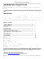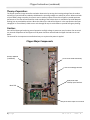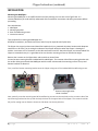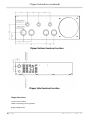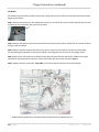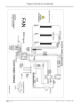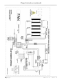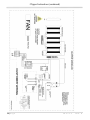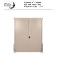
1
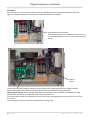
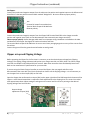
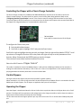
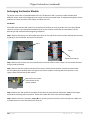
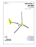
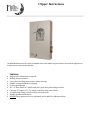
Clipper Instructions The MNCLIPPER works alone or with the MidNite Solar Classic MPPT Charge Controller to provide the highest level of performance and protection possible. Features: Helps protect turbine from overspeed. Braking feature included. Convenient switching between run / turbine slowing. Settable voltage threshold for clipping. 50 Amp pass-through. D.C. or Three Phase AC models with heavy duty three phase bridge rectifier. Converts AC input to D.C. for charge controllers such as the Classic. Available with a range of built-in diversion load values. Durable powdercoated chassis. MNSPD Surge protective devices (optional) can be added for added protection. Clipper Instructions (continued) IMPORTANT SAFETY INSTRUCTIONS SAVE THESE INSTRUCTIONS - These instructions contain important safety and operating instructions for the MidNite Solar MNClipper. If you do not fully understand any of the concepts, terminology, or hazards outlined in these instructions, please refer installation to a qualified dealer, electrician or installer. These instructions are not meant to be a complete explanation of a renewable energy system. GENERAL PRECAUTIONS If service or repair should become necessary, contact MidNite Solar Inc. Improper servicing may result in a risk of shock, fire or explosion. To reduce these risks, disconnect all wiring before attempting any maintenance or cleaning. Turning off the inverter will not reduce these risks. Do not work alone. Someone should be in the range of your voice or close enough to come to your aid when you work with or near electrical equipment. Remove rings, bracelets, necklaces, watches etc. when working with batteries or other electrical equipment. Power from RE sources makes a very effective arc welder with dire consequences if one of the welded pieces is on your person. Table of contents. Theory of operation ---------------------------------------------------------------------Major Components ---------------------------------------------------------------------Installation --------------------------------------------------------------------------------Wiring the Clipper -----------------------------------------------------------------------Knockout Locations ---------------------------------------------------------------------Clipper set-up and clipping voltage--------------------------------------------------Using with a Classic MPPT Charge Controller--------------------------------------Clipper Operation ------------------------------------------------------------------------Resistor Module --------------------------------------------------------------------------Wiring Diagrams -------------------------------------------------------------------------Warranty -----------------------------------------------------------------------------------Contact information ----------------------------------------------------------------------- 3 3 4 5 6 8 9 9 10 12 16 16 Notice of Copyright MidNite Solar Clipper User’s Manual Copyright © 2012 all rights reserved. Disclaimer Unless specifically agreed to in writing, MidNite Solar Inc. (a) Makes no warranty as to the accuracy, sufficiency or suitability of any technical or other information provided in its manuals or other documentation. (b) Assumes no responsibility or liability for loss or damage whether direct, indirect, consequential or incidental, which might arise out of use of such information. The use of any such information will be entirely at the user's risk. MidNite Solar 17722 - 67thAve N.E. Arlington, Wa 98223 U.S.A. 360.403.7207 [email protected] www.midnitesolar.com 2|Page 10-171-1 REV: B Clipper Instructions (continued) Theory of operation: The Clipper protects charge controllers and other electronics by sensing the incoming voltage from the turbine and using its internal loads as needed to hold down the incoming voltage to a value that you set. When used with a Classic MPPT charge controller, the Classic uses its auxiliary output to control the Clipper to provide optimum performance. The internal load should be sized according to the turbine that it is used with to provide adequate braking, but not overload the turbine. When the slider on the side of the Clipper is in the stop position the input voltage (DC or Three Phase) is held to zero volts through 50 amp circuit breakers to provide emergency braking. Caution: Parts of the Clipper get hot during normal operation and high voltage is present at many locations. Do not touch any internal components of the Clipper until all power has been removed and the Clipper has had time to cool down. The internal fan is temperature controlled and may run anytime that power is applied. Clipper Major Components Resistor Module (Load Bank) Three Phase Solid State Relay Three Phase Bridge Rectifier RUN/STOP Slider 50 Amp Input Breakers Main PCB Three Phase Input from Turbine 3|Page 10-171-1 REV: B Clipper Instructions (continued) INSTALLATION: Mounting the MNClipper: Mounting the MNClipper is not a difficult task but a little planning now can save a lot of grief later. It is recommended that you read and fully understand all the installation instructions and safety precautions before proceeding. Parts Included are: 1 - MNClipper 2 - Mounting brackets 4 - 6mm Threadforming screws 1 - Instruction manual Tools required for mounting the MNClipper are: #2 Phillips screwdriver, stud finder and a level. A drill may be required to drill pilot holes. The Clipper has a type 1 enclosure and should be installed only in a protected dry indoor location with adequate ventilation on all sides. The air exiting the exhaust of the Clipper will be hot when the Clipper is slowing the turbine. A minimum of 8” of clearance on the sides and bottom and 24” above the Clipper are recommended. The Clipper is somewhat heavy it is a good idea to be sure that the mounting surface can handle the weight. Remove the 4 screws on the Clipper door and set aside to reinstall later. Locate the two mounting brackets included with the MNClipper. The narrower side of the mounting bracket with the smaller holes goes towards the MNClipper with the other side towards the mounting surface. The top and bottom brackets are identical. First, install the bottom mounting bracket onto the Clipper using two of the included M6 threadforming screws. Bottom mounting bracket shown installed. Next, partially screw the remaining two M6 threadforming screws into the two holes on the narrower side of the top mounting bracket that line up with the keyhole slots on the upper back of the Clipper. The screws should be left just far enough out to allow the chassis to slide down into the keyhole slot. 4|Page 10-171-1 REV: B Clipper Instructions (continued) Use a level and hold the top mounting bracket on the wall in a horizontal position and mark on the wall where the mounting screw holes will be placed. If required, drill pilot holes using a #10 (0.193” diameter) drill bit. Drill appropriately sized holes for anchors (sold separately) when installing on non-wood surfaces. Secure the top mounting bracket to the wall using three ¼ X 1½ hex-head lag bolts. Make sure that the outer two lag bolts are securely fastened into a stud. If mounting to other than a wood wall or surface, use appropriate screws and anchors as required. Lift the Clipper and place the keyhole slots (located on the upper back of the Clipper) directly over the mounting screws on the upper mounting bracket on the wall and lower into place. Tighten the op mounting screws to secure the Clipper to the mounting bracket. Secure the bottom mounting bracket to the wall using three ¼ X 1½ hex-head lag bolts. Be sure to observe NEC mounting height requirements. Wiring the Clipper: Do not alter factory pre-wired connections! Typical three phase system with Classic and Clipper (Shown with optional equipment) The Clipper is a complex device and should only be installed by an experienced installer! The wiring diagrams beginning on page 12 show the various configurations of the Clipper. The wiring inside the dashed lines shows the connections in from the turbine and out to the charge controller. Be sure to comply with all local and national code requirements including National Electrical Code ANSI/NFPA 70. Use Class 1 wiring methods for field wiring connections to terminals of a Class 2 circuit. Use only 14-2/0 gauge AWM wire. Select the wire gauge used based on the protection provided by the circuit breakers/fuses. 5|Page 10-171-1 REV: B Clipper Instructions (continued) Clipper Bottom Knockout Location Clipper Side Knockout Location Clipper Dimensions: 25.411 Tall X 15.41 Wide 26.961 Tall including mounting brackets Shipping Weight 55 lbs. 6|Page 10-171-1 REV: B Clipper Instructions (continued) AC Clippers: Connect phases 1, 2 and 3 from the turbine to the corresponding lugs on the large terminal block at the lower right of the Clipper. Knockouts are located on the sides and bottom of the Clipper. Three phase input from turbine Terminal block accepts 2/0-14 AWG wire. Be sure to use a heavy enough gauge wire to carry all the current from the turbine Ground Busbar Connect the positive and negative outputs from the Clipper PCB Terminal block TB3 to the charge controller positive and negative inputs (refer to the documentation that came with your charge controller). Observe proper polarity. Severe damage could result from improper wiring. Knockouts are located on the sides and bottom of the Clipper. See Page 6 for knockout locations and sizes. The terminal block accepts 6-20 AWG wire. Be sure to use a heavy enough gauge wire to carry all the current from the turbine. Connect the ground from the ground terminal busbar to earth ground. 7|Page 10-171-1 REV: B Clipper Instructions (continued) DC Clippers: Connect the positive and negative output from the turbine to the positive and negative inputs on the PCB terminal block TB2. It is the two position terminal block marked “Bridge Rect”. Be sure to observe proper polarity. TB2 Connect DC output from turbine here. Terminal block accepts 6-20 AWG wire. Observe polarity. Connect the positive and negative outputs from the Clipper PCB Terminal block TB3 to the charge controller positive and negative inputs (refer to the documentation that came with your charge controller). Observe proper polarity. Severe damage could result from improper wiring. Knockouts are located on the sides and bottom of the Clipper. See Page 6 for knockout locations and sizes. The terminal block accepts 6-20 AWG wire. Be sure to use a heavy enough gauge wire to carry all the current from the turbine. Connect the ground from the ground terminal busbar to earth ground. Clipper set-up and Clipping Voltage: Before operating the Clipper for the first time it is necessary to set the desired upper voltage limit (Clipping Voltage). The clipping voltage is determined by what your charge controller can safely allow. The Classic charge controller is available in 150, 200 and 250 volt versions. Most other controllers have considerably lower limits. Refer to the manufacturer’s specification for your controller. If you are using the Classic Charge Controller to control the Clipper, then see page 9 and refer to the documentation that came with your Classic for details on how to set the Clipping Voltage. It is still necessary to set the upper limit on the trimpot (VR1) as a fail-safe. Open the clipper door and locate the trimpot (VR1) at the upper right side of the PCB located at the bottom of the Clipper. A small slotted screwdriver is required to make adjustments to the clipping level. The control is marked with approximate values. When setting the voltage turn the control until the arrow is pointing at the desired clipping voltage from 0 to 250 volts. Output voltage adjustment trimpot (VR1) 8|Page 10-171-1 REV: B Clipper Instructions (continued) Controlling the Clipper with a Classic Charge Controller. The Classic charge controller has a PWM (Pulse Width Modulation) output that can be used to control the Clipper’s output voltage. This will provide very precise control of the power being produced. Refer to the “Configuring Auxiliary Input/Output” section in the Classic manual for settings and connections for the Classic. To use this feature it will be necessary to run two wires from the Classic AUX2 output to the terminal block TB6 on the Clipper PCB. 18 ga twisted pair is recommended to reduce noise. TB6 AUX PWM Input used for external control of the Clipper. To configure the Classic's Aux ports: Push the Main Menu button Scroll left or right to highlight “AUX” and push the Enter button. Scroll left or right to highlight the relay you wish to change. Push the right soft key labeled “SETUP”. Scroll up or down to change the function of the relay. Select the right soft key to set the parameters of the function. When finished push the ENTER button to save the changes. The main Aux Screen shows both Aux1 and Aux2 functions Select the AUX 2 function “Clipper Control” This mode is intended to control the MidNite Clipper. It will send out a PWM signal whenever the controller is loading the turbine because the battery is full or close to it. There are no adjustment in this mode the Classic is preprogrammed with the best parameters to control turbine RPM. Parallel Clippers: On larger turbines two Clippers may be used in parallel for greater capacity. When used with 1 or 2 Classic charge controllers the AUX2 output from the Master Classic is connected to the AUX PWM inputs of both Clippers. The AC Inputs are applied to the inputs of each Clipper. Operating the Clipper: Once the Clipper is installed and wired in all that is left to do is to push the slider on the Clipper door to the “RUN” position. The Clipper will now maintain a safe voltage input to the charge controller as well as slow the turbine in high wind to increase turbine life and protect from damage. The first few times that the Clipper operates you may notice a hot smell. This is normal and will fade quickly with use. 9|Page 10-171-1 REV: B Clipper Instructions (continued) Exchanging the Resistor Module: The Clipper comes with a replaceable diversion load. The diversion load is a resistor module available with different resistor values and configurations to provide a variety of possible loads. To replace/exchange the resistor module first remove all power to the Clipper and allow it to cool. AC Models: AC models come with the load resistors for each phase wired either in series or parallel, there are also multiple values for resistors. The replacement module may be any one of these. Verify that the new module is of the desired type and resistance before beginning installation. Step 1. Remove the two wires to the temperature sensor on the side of the resistor module. Remove the terminals by pulling on the red handles. Do not pull on the wires. Step 1. Step 2. Remove these wires Step 2. Remove the six wires from the terminal block at the base of the resistor module. Do not remove the wires that go inside the module. Step 3. Remove the two screws at the base of the resistor module and set aside to use with the new module. Lift the module gently upward and to the right to remove the module’s mounting tabs from the slots on the Clipper chassis and remove the old module. Remove the two screws at the bottom of the resistor module. Step 3. Step 4. Position the new module in the Clipper chassis with the terminal block toward the middle of the Clipper and slide the mounting tabs into position. Secure the module with the screws removed in Step 3. Step 5. Replace the wires removed in steps 1 & 2 in the same positions that they were removed from. Make sure to torque the wires in the terminal block to 20 in-lbs. 10 | P a g e 10-171-1 REV: B Clipper Instructions (continued) DC Models: DC models come prewired to provide various loads. Verify that the new module is of the desired resistance before beginning installation. Step 1. Remove the two wires to the temperature sensor on the side of the resistor module. Remove the terminals by pulling on the red handles. Do not pull on the wires. Step 2. Remove the two wires from the terminal block at the base of the resistor module. Do not remove the wires that go inside the module. Step 3. Remove the two screws at the base of the resistor module and set aside to use with the new module. Lift the module gently upward to remove the module’s mounting tabs from the slots on the Clipper chassis. Step 4. Position the new module in the Clipper chassis with the terminal block toward the middle of the Clipper and slide the mounting tabs into position. Secure the module with the screws removed in Step 3. Step 5. Replace the wires removed in steps 1 & 2 in the same positions that they were removed from. All Midnite Solar products are assembled under the watchful eye of Midnite the cat. 11 | P a g e 10-171-1 REV: B Clipper Instructions (continued) 12 | P a g e 10-171-1 REV: B Clipper Instructions (continued) 13 | P a g e 10-171-1 REV: B Clipper Instructions (continued) 14 | P a g e 10-171-1 REV: B Clipper Instructions (continued) 15 | P a g e 10-171-1 REV: B Clipper Instructions (continued) MIDNITE SOLAR INC. LIMITED WARRANTY MidNite Solar Power electronics, sheet metal enclosures and accessories MidNite Solar Inc. warrants to the original customer that its products shall be free from defects in materials and workmanship. This warranty will be valid for a period of five (5) years for all products except the MNKID Charge Controller which will be two (2) years. At its option, MidNite Solar will repair or replace at no charge any MidNite product that proves to be defective within such warranty period. This warranty shall not apply if the MidNite Solar product has been damaged by unreasonable use, accident, negligence, service or modification by anyone other than MidNite Solar, or by any other causes unrelated to materials and workmanship. The original consumer purchaser must retain original purchase receipt for proof of purchase as a condition precedent to warranty coverage. To receive in-warranty service, the defective product must be received no later than two (2) weeks after the end of the warranty period. The product must be accompanied by proof of purchase and Return Authorization (RA) number issued by MidNite Solar. For an RMA number contact MidNite Solar Inc., 17722 67th Ave NE, Arlington, WA 98223 (360) 4037207. Purchasers must prepay all delivery costs or shipping charges to return any defective MidNite Solar product under this warranty policy. Except for the warranty that the products are made in accordance with, the specifications therefore supplied or agreed to by customer: MIDNITE SOLAR MAKES NO WARRANTY EXPRESSED OR IMPLIED, AND ANY IMPLIED WARRANTY OF MERCHANTABILITY OR FITNESS FOR A PARTICULAR PURPOSE WHICH EXCEEDS THE FOREGOING WARRANTY IS HEREBY DISCLAIMED BY MIDNITE SOLAR AND EXCLUDED FROM ANY AGREEMENT MADE BY ACCEPTANCE OF ANY ORDER PURSUANT TO THIS QUOTATION. MIDNITE SOLAR WILL NOT BE LIABLE FOR ANY CONSEQUENTIAL DAMAGES, LOSS OR EXPENSE ARISING IN CONNECTION WITH THE USE OF OR THE INABILITY TO USE ITS GOODS FOR ANY PURPOSE WHATSOEVER. MIDNITE SOLAR’S MAXIMUM LIABILITY SHALL NOT IN ANY CASE EXCEED THE CONTRACT PRICE FOR THE GOODS CLAIMED TO BE DEFECTIVE OR UNSUITABLE. Products will be considered accepted by customer unless written notice to the contrary is given to MidNite Solar within ten (10) days of such delivery to customer. MIDNITE SOLAR is not responsible for loss or damage to products owned by customer and located on MIDNITE SOLAR’S premises caused by fire or other casualties beyond MIDNITE SOLAR’s control. This warranty is in lieu of all other warranties expressed or implied. MIDNITE SOLAR INC. 17722 67TH AVE NE ARLINGTON, WA 98223 Email: [email protected] PH: 360.403-7207 FAX: 360-691-6862 16 | P a g e 10-171-1 REV: B