1
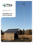
14000 Burn Rd
Arlington, WA 98223
USA
Ph (425)374-9060
www.midnitesolar.com
SURGE PROTECTOR DEVICE
INSTALLATION MANUAL
The MidNite Solar Surge Protector Device (MNSPD) is a Type 1 device, designed for
indoor and outdoor applications. Engineered for both AC and DC electric systems, it
provides protection to service panels, load centers or where the SPD is directly connected to
the electronic device requiring protection. Maximum protection will only be achieved if the
SPD is properly installed. Please read the following installation manual carefully and follow
the instructions.
The MidNite Solar SPD is offered in three different voltages to maximize the required
protection level. Protection is achieved by reducing the clamping voltage to a safe voltage
that your system can sustain without damaging any electronics in the system. By using the
chart on page 2 select the SPD’s that provide the protection your system requires.
The MidNite Solar SPD voltage rating should be chosen according to the nominal voltage of
the system. Do not install an SPD with Maximum Continuous Operating Voltage (MCOV)
below the nominal voltage of the system; this will deteriorate the SPD and making it
unavailable when you most need it.
Midnite Solar Surge Protection Device.
8-009-1
Part No.
MNSPD115
MNSPD300
MNSPD600
Nominal Voltage
0 to 150 VDC
0 to 300 VAC
0 to 385 VDC
0 to 480 VAC
0 to 640 VDC
MCOV
VRMS @1mA
180V (162-198)
470V (423-517)
780V (702-858)
ClampV @ 100A
Current 8/20µs
295V
775V
1290V
115kA (Full Device)
57.5kA (Each Section)
115kA (Full Device)
57.5kA (Each Section)
115kA (Full Device)
57.5kA (Each Section)
Energy Absorption
1120 J (Full Device)
560 J (Each Section)
3130 J (Full Device)
1560 J (Each Section)
4320 J (Full Device)
2160 J (Each Section)
Suggested Placement
12V,24V,48V DC battery
circuits
120/240VAC circuits,
offgrid PV combiners and
charge controller inputs up
to 300VDC,
316V/480VAC circuits
Grid tie PV combiners
Grid tie inverter input
I peak (8/20µs)
(Current)
Diagnostics
Dual Operating LED Indicators. When voltage is present
Operating Temperature Range
-40°c to +85°c
Nominal Discharge Current
INA
57.5kA
Thermal Disconnector Internal
Internal
Response time
<1micro sec.
DANGER: Electrical shock or burn hazard. Installation of this SPD should only be made
by qualified personnel. Failure to lockout electrical power during installation or maintenance
can result in fatal electrocution or severe burns.
CAUTION: Check to make sure system voltages do not exceed the SPD voltage
requirement and the correct SPD voltage/model has been selected.
CAUTION: This unit must be installed in accordance with the National Electrical Code
(ANSI/NFPA-70) and applicable local codes.
CAUTION: Ungrounded power systems are inherently unstable and can
allow excessively high line-to-ground voltages during certain fault conditions.
During these fault conditions any electrical equipment, including an SPD, may
be subjected to voltages which exceed their designed ratings. This information
is being provided to the user so that an informed decision can be made before
installing any electrical equipment on an ungrounded power system.
ATTENTION: les systèmes d'alimentation sans terre sont intrinsèquement
instables et peuvent produire des tensions de ligne trop élevé-sol au cours de
certaines conditions de défaut. Au cours de ces conditions de défaut, tout
équipement électrique, y compris un SPD, peut être soumis à des tensions qui
dépassent leurs notations conçu. Cette information est fournie à l'utilisateur
afin qu'une décision éclairée puisse être prise avant l'installation de tout
équipement électrique sur un système d'alimentation sans fondement.
NOTICE: Do not cut wires until the SPD is mounted and minimum wire lengths have been verified. All
connection leads should be cut to minimum possible length; never coil or push aside excess length.
INSTALLATION INSTRUCTIONS
1. *Verify system voltage. Measure L-N, L-G, L-L and N-G of the AC system. DC systems measure from
positive and negative input. Confirm that the SPD is correctly rated for the system to which it is to be connected
to. Do this by comparing the measured voltages to the SPD voltage ratings shown on the product’s rating label.
The measured voltage should NOT BE ABOVE the maximum continuous operating voltage (MCOV) of the
surge protector device rating, during normal operation. Some circuits like PV arrays may need to be calculated
for worst case maximum operating voltages.
2. Identify proper location for the SPD. Locate the unit as close as physically possible to the panel being
protected and as close to the electrical connection as possible. Avoid excess lead lengths and the need for sharp
bends in the wires. Refer to fig 1.1 and fig 1.2 as an example.
3. Install green wire to the GROUND bus bar. In AC circuits it is not uncommon to connect the green wire to
AC neutral, install the white sleeving over the green wire when connecting to AC neutral. Make sure the green
wire takes the shortest path to earth ground!!
4. Connect phase conductors. The phase wires are black and red in color. The orientation is not critical to the
operation. (AC) With the POWER OFF, connect one wire to AC HOT IN (line) and other wire to AC HOT
OUT (load) as shown in fig. 1.2 (DC) connect the red wire to PV + and the black wire to PV - or battery minus.
PV combiners get installed as shown in figure 1.1
5. Apply voltage to SPD. Both LED’s in the SPD should glow blue as a sign that voltage is present in system,
SPD is connected correctly and working and the system is protected. Note. LED’s will only be on when voltage
is present. In PV circuits the lights will go out at night because arrays are not producing voltage. This does not
indicate that the SPD is broken. If voltage is present and the blue LED’s are off, the SPD needs repair. When
connecting one half of the SPD to PV- and ground, the PV- led will not light. The circuit is protected, but there
is normally no voltage between PV- and ground.
Note:
1) This product “Contains No Serviceable Parts”.
2) USE SUPPLY WIRE SUITABLE FOR 90° C.
"The conductors used to connect the SPD to the line or bus shall not be
any longer than necessary and shall avoid unnecessary bends"
fig. 1.2
Use screw and a washer for terminal connection
On MNPV combiner
PV PLUS BUS
(red wire)
fig 1.1
AC IN
(black/red
AC OUT
(black/red wire)
GROUND
(green wire)
BATTERY
NEGATIVE
(black wire)
Installation shown in a MidNite Solar 120v E-Panel.
Installation shown in a MNPV12.
Configured for 2grid tie inverters
The following represents a wiring diagram of SPD’s in a typical system.
INSTALLATION SHOWN WITH MIDNITE SOLAR E-PANEL AND
COMBINER BOX. SPD CAN BE USED WITH ANY ELECTRIC PANEL
THAT IS WITHIN THE SPD RATINGS.
Figure 1.5
In a utility connected home, one of the most vulnerable points of
entry is the service entrance panel. All house wiring connects to
the service entrance panel and therefore everything plugged in is
at risk. The MidNite SPD300 provides protection against near
lightning strikes up to 115,000 amps of surge current. Hooking up
to the service entrance can be done in a few different ways.
Figure 1.6 shows the two hot wires connected to a 240V circuit
breaker. The circuit breaker in this case has no other house loads
and is dedicated strictly to the SPD. This was done just to have a
convenient place to connect the hot leads of the SPD to the panel.
It is not required to have a circuit breaker or fuse in series with
the SPD. The SPD has its own internal fusing.
Figure 1.6
Figure 1.7 shows a more economical method to connect the SPD to
the service entrance distribution panel. This installation utilizes a
240V breaker that is already in use. This could be a deep well pump,
air conditioner etc. Unless the circuit breaker is listed to have two
wires connected, you must pigtail the wiring as shown. Breakers that
are listed for two wires are very rare, so this method of installing the
SPD is probably your best bet.
Figure 1.7
Some homes have surface mounted distribution panels.
Those are easy to add an SPD to. Simply pop out a 7/8”
diameter knockout and mount the SPD on the hole.
Other homes have service entrances that are flush
mounted and are not exposed. This type of installation will
benefit from the MidNite SPD Flush mount box. Cut a hole
in the sheet rock close to the distribution panel and mount
the box in the hole. Secure the box after wiring is
completed using drywall anchors. Make sure to grommet
the hole in the distribution box.
Figure 1.8
*MIDNITE SOLAR INC. LIMITED WARRANTY. MidNite Solar Surge Protection Device (SPD)
Midnite Solar Inc. warrants to the original customer that the SPD products shall be free from defects in materials and workmanship for a period of
five (5) years. At its option, Midnite Solar will repair or replace at no charge any SPD that proves to be defective within such warranty period. This
warranty shall not apply if the Midnite Solar product has been damaged by unreasonable use, accident, negligence, service or modification by
anyone other than Midnite Solar, or by any other causes unrelated to materials and workmanship. The original consumer purchaser must retain
original purchase receipt for proof of purchase as a condition precedent to warranty coverage. To receive in-warranty service, the defective product
must be received no later than two (2) weeks after the end of the warranty period. The product must be accompanied by proof of purchase and
Return Authorization (RA) number issued by Midnite Solar. For an RMA number contact Midnite Solar Inc, 17722 67th Ave NE unit C, Arlington,
WA 98223 (425) 374-9060. Purchasers must prepay all shipping charges to Midnite Solar product under this warranty policy. Except for the
warranty that the products are made in accordance with the specifications therefore supplied or agreed to by customer, MIDNITE SOLAR MAKES
NO WARRANTY IF SURGE PROTECTOR DEVICE SECURITY TAB HAS BEEN BROKEN OR IF SPD MCOV RATING IS CHOSEN BELOW
SYSTEM’S NOMINAL VOLTAGE. Products will be considered accepted by customer unless written notice to the contrary is given to MIDNITE
SOLAR within ten (10) days of such delivery to customer. MIDNITE SOLAR shall not in any case be liable for any event occurring or defect
discovered with regard to said product unless written notice thereof is given to MIDNITE SOLAR within ninety (90) days of such product delivery to
customer. MIDNITE SOLAR is not responsible for loss or damage to other products owned by customer and beyond MIDNITE SOLAR’s control.
This warranty is in lieu of all other warranties expressed or implied.
MIDNITE SOLAR INC. 17722 67TH AVE NE UNIT C ARLINGTON, WA 98223
Email: [email protected] PH: 425-374-9060 FAX: 360-691-6862