1
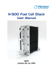
H-1000 Fuel Cell Stack
Think Big…
User Manual
V1.3
Updated 16 June 2009
1
OVERVIEW OF THE STACK
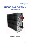
Thank you for choosing our fuel cell stack. The Horizon 1000W fuel cell stack is an air-cooled,
light weight and compact fuel cell stack.
Please read all instructions carefully prior to product use and keep this manual for future
reference.
Further copies can be obtained from Horizon Fuel Cell Technologies or by emailing
[email protected]
Please refer to the Horizon website for latest information www.horizonfuelcell.com
Specifications and descriptions in this document were in effect at the time of publication.
Horizon Fuel Cell Technologies reserves the right to change specifications, product
appearance or to discontinue products at any time.
Information on the stack warranty can be found on the warranty card that comes with this
stack system.
IMPORTANT
In order for the warranty to come into effect the stack must be registered on the Horizon
Warranty Page at:
www.horizonfuelcell.com/warranty.htm
Do not attempt, under any circumstance, to disassemble or
inappropriately tamper with the fuel cell. There will be no returns,
refunds or exchanges should disassembly or tampering occur. If you
have questions or need help with regards to the fuel cell and its
technology contact [email protected].
2
Table of Contents
1. TERMINOLOGY .......................................................................................... 4 2. TECHNICAL SPECIFICATIONS ................................................................. 5 3. SYSTEM SET-UP........................................................................................ 6 4. SYSTEM SETUP DIAGRAM ..................................................................... 13 5. POLARIZATION CURVES ........................................................................ 14 6. OPERATING INSTRUCTIONS ................................................................. 15 7. SIMPLIFIED DRAWING OF HFCT MEASUREMENT STAND ................. 16 8. TROUBLESHOOTING & SUGGESTIONS: .............................................. 18 3
1. Terminology
PEM fuel cell: a PEM (Proton Exchange Membrane) fuel cell is a
device that converts hydrogen and oxygen into water and electricity.
Reactants: reactant is a material used to start a chemical reaction. In
the fuel cell the reactants are air and hydrogen by which the electricity
will be generated.
Humidification: humidity that the fuel cells need for running.
Blower: supply air to the fuel cells and meanwhile decrease the
temperature in the stack.
Mass flow per minute: the total amount of the hydrogen flow to the
fuel cell every minute,which the hydrogen supply can be calculated.
HFCT: Horizon Fuel Cell Technologies
4
2. Technical specification
Type of fuel cell………………….……
........................................
PEM
Number of cells..............................................
72
Rated power...........................................
1000W
Rated [email protected]
Output voltage range...........................
39V-69V
Weight (with fan & casing)............ 4.2kg (9.3lbs)
Size..................................................
324x220x122mm (12.8x8.7x4.8in)
Reactants............................................
Hydrogen and Air
Rated H2 consumption......................
14l/min (847in³/min)
Hydrogen pressure................................
0.5-0.6Bar (7.2-9.4PSI)
Controller weight....................................
0.45kg (0.99lbs)
Hydrogen supply valve voltage...................
12V
Purging valve voltage..................................
12V
Blower voltage.............................................
12V
Ambient temperature.............................
5-30°C (41-86°F)
Max stack temperature..........................
65°C (149°F)
Hydrogen purity.....................................
99.999% dry H2
Humidification.........................................
Self-humidified
Cooling..................................................
Air (integrated cooling fan)
Start up time.............................................
Immediate
Efficiency of system.........................
40%@43V
*the flow rate may change with the power output
**system electronics need external power supply
5
3. System Set-Up
STEP1: Connect the connectors of the controller and the stack (1A, 1B), to get the blower, the
temperature sensor, the hydrogen supply valve and the purge valve under control. The
finished connection is shown in 1C.
1B
1A
1C
6
STEP2:Connect the controller and the stack as the output power also should be under
controlled. The finished connection is shown in 2E.
2A
2B
2C
2D
2E
7
STEP3:Connect the stack with a stabilized voltage supply through the “DC 13V” connectors
(3A), and the voltage of the power should be between 13V and 15V.
3A
STEP4:Lay the Hydrogen supply valve and the purge valve at the back of blower in case of
the damage caused by the Hydrogen leakage.
4A
STEP5:Keep the SCU (Short Circuit Unit) switch at the 0 in usual use. Only if the
performance of the stack is going down, please switch it to the 1 to activate the stack.
5A
8
STEP6:Connect the outside Hydrogen supply valve to the stack. The Hydrogen supply valve
will prevent the damage from the Hydrogen while the stack is off. Notice the direction of the
connection of the Hydrogen supply valve. The finished connection is shown in 7H.
6A
6B
6C
6C
6D
6E
6E
6F
9
6G
6H
STEP7:Connect the stack with the purge valve through the filter for a longer runtime and a
better performance (7A-7J). If not, the gas out of stack may have a negative effect on the
purge valve after a long-time running. Connect the output of the purge valve to a place away
from the stack in case of the damage caused by the Hydrogen leakage (7K, 7L).
7A
7B
7C
7D
10
7E
7F
7G
7H
7I
7J
11
7K
7L
STEP8: Check all the connection before and link the load to the stack through the
connectors as shown in 8A.
8A
STEP9: Start the Hydrogen supply, the stabilized voltage supply and the ON/OFF
switch.
9A
12
4. System setup diagram
13
5. Polarization curves
14
6. Operating instructions
Step 1: Set up the fuel cell system according to the diagram above, make sure that:
-
The external DC power supply voltage is between 12V to 15V.
The pressure is between 0.05 to 0.065Mpa. (7.2-9.4psi)
Step 2: Connect the load to the “GND” and “Load +”.
Step 3: Start the power supply and Hydrogen supply.
Step 4: Press ON button and the fuel cell system is ready to use.
15
7. Simplified drawing of HFCT measurement stand
13V
external
power supply
Load
Pressure
regulator
H2 source
Horizon FC system
1. Use 99.999% pure DRY hydrogen.
2. Use pressure regulator to adjust the pressure to 0.05Mpa (7.2psi) to 0.065Mpa (9.4psi),
which means the pressure inside the stack will stay 0.065Mpa (9.4psi) under any
circumstances.
Note: Higher pressure may cause H2 leakage; lower pressure will affect the fuel cell
performance.
a. If you use the testing station to test the system, the following measurement may damage
the fuel cell: Use the mass flow controller to maintain the flow rate, and use dead ended valve
inside the station to close fuel cell purging, because the power draw from the fuel cell may
change with the load.
b. If the set H2 flow rate value is higher than what can be consumed, the pressure may
increase then the fuel cell will be damaged.
c. If the set flow rate value is lower than what can consume, the pressure may drop then the
fuel cell performance will be affected.
Suggestion: Therefore please maintain the H2 pressure into the fuel cell system between
0.05Mpa (7.2psi) to 0.065Mpa (9.4psi).
If you want to use the mass flow controller to control the flow rate, please make sure it has
flow tracking function. (the flow rate will change according to the fuel cell power output)
16
13V external
power supply
Load
Pressure
regulator
Mass
flow
Horizon
FC system
Pressure
sensor
H2 source
Dead ended valve
Testing station
3. Use 13V external electrical power supply, which will supply power to the controller/cooling
blower/valves in the system. You can also use battery to supply power, the periphery will
consume about 6A current(1000W), you can use this to calculate how long the battery can
last, for example, if you use a 12V/1.3Ah lead acid battery, it can last for about 12 mins, if you
want to let the system run longer you can just choose higher capacity battery.
4. At horizon we use constant voltage mode to test our product, we also highly suggest our
customer use constant voltage mode.
17
8. Troubleshooting & suggestions
If the stack is not used for a long time (months), it will take a little time to get the
manual power, It need 5-30mins
If the system shuts down by itself check the following details:
1.
2.
3.
4.
Make sure you have connected Hydrogen and external power supply.
Make sure the external voltage is 12V -15V
Make sure you have hydrogen supply
Make sure the load is below 1000W, because the controller will protect the stack from
drawing too much current.
5. Check whether the fuel cell temperature is below 65ºC, the system will shut off if it is
above 65ºC.
Note:
1. Disconnect the hydrogen supply completely if the fuel cell stack is not in
operation for more than 4 hours.
2. Use a tube to connect the fuel cell stack hydrogen inlet to the outlet if the fuel
cell stack is not in operation.
3. Ensure that the 99.999% of the Hydrogen used is dry. Overuse of humidifiers
may cause irreparably damage.
4. Ensure that white nozzle on the purging valve is connected to the fuel cell
Hydrogen outlet.
5. The hydrogen outlet must be 20cm away from the fuel cell stack, because the
MEA will be damaged permanently if there is hydrogen and oxygen available
simultaneously
WARNING
Do not attempt, under any circumstance, to disassemble or
inappropriately tamper with the fuel cell. There will be no returns, refunds
or exchanges should disassembly or tampering occur. If you have
questions or need help with regards to the fuel cell and its technology
contact [email protected].
18