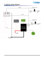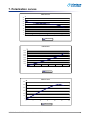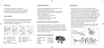
1
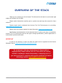
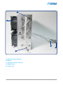
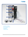
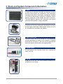
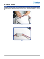
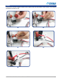
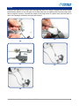
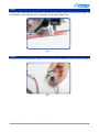
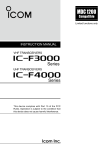
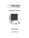
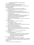
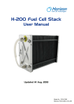
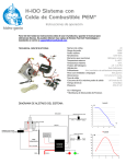
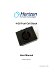
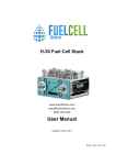
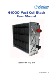
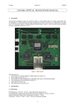
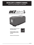
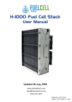
H-500 Fuel Cell Stack
User Manual
V2.0
Updated 25 Jan 2010
OVERVIEW OF THE STACK
Thank you for choosing our fuel cell stack. The Horizon fuel cell stack is an air-cooled, light
weight and compact fuel cell stack.
Please read all instructions carefully prior to product use and keep this manual for future
reference.
Further copies can be obtained from Horizon Fuel Cell Technologies or by emailing:
Please refer to the Horizon website for latest information: www.horizonfuelcell.com
[email protected]
Specifications and descriptions in this document were in effect at the time of publication.
Horizon Fuel Cell Technologies reserves the right to change specifications, product appearance or
to discontinue products at any time.
IMPORTANT
In order for the warranty to come into effect the stack must be registered on the Horizon
Warranty Page at: www.horizonfuelcell.com/warranty.htm
Do not attempt, under any circumstance, to disassemble or
inappropriately tamper with the fuel cell. There will be no returns,
refunds or exchanges should disassembly or tampering occur. If
you have questions or need help with regards to the fuel cell and its
technology contact: [email protected]
H-500 Fuel Cell Stack User Manual V2.0
Table of Contents
1. Terminology............................................................ 1
2. Stack and System Component Information............. 5
3. Technical Specifications......................................... 7
4. System Set Up....................................................... 8
5. Notes fot the set up ................................................ 14
6. System Setup Diagram .......................................... 16
7. Polarization Curves................................................ 17
8. Operating Instructions............................................ 18
9. Trouble Shooting & Suggestions............................ 18
H-500 Fuel Cell Stack User Manual V2.0
1. Terminology
PEM fuel cell:
a PEM (Proton Exchange Membrane) fuel cell is a device that converts hydrogen and oxygen into
water and electricity.
Reactants:
reactant is a material used to start a chemical reaction. In the fuel cell the reactants are air and
hydrogen by which the electricity will be generated.
Humidification:
humidity that the fuel cells need for running.
Blower:
supply air to the fuel cells and meanwhile decrease the temperature in the stack.
Mass flow per minute:
the total amount of the hydrogen flow through the fuel cell every minute, which the hydrogen supply
can be calculated.
HFCT:
Horizon Fuel Cell Technologies
H-500 Fuel Cell Stack User Manual V2.0
1
A
B
E
D
C
A: Hydrogen Inlet connector
B: Blower
C: Hydrogen Outlet connector
D: Supply valve
E: Purge valve
H-500 Fuel Cell Stack User Manual V2.0
2
E
C
D
B
A
A: Lable (FC- and Load-)
B: FC- and Load- connecter
C: FC+ connecter
D: Lable (FC+)
E: Warning Labels
H-500 Fuel Cell Stack User Manual V2.0
3
A
C
B
L
E
H
J
K
D
F
G
I
A: Logo
B: LED
C: Product No.Label
D: Connect plug
E: SCU(short circuit units) switch
F: ON/OFF button
G: Connect to FC+
H: Connect to FCI: Connect to Load+
J:Controller power supply DC 13V+
K:Controller power supply DC 13VL:LCD connecter
H-500 Fuel Cell Stack User Manual V2.0
4
2. Stack and System Component Information
1. Stack
Is made up of plate-like cells with air channels to allow
the flow of air across the membrane. The membrane
facilitates the flow of Hydrogen creating the release
of electrons. Electrically conductive separator plates
between each pair of cells enable the flow of electrons.
The stack aspect is that they are all placed on top of each
other and held together by epoxy endplates.
2. H2 Supply Valve and purge
It controls the H2 input. When the controller turns on, also
the H2 supply valve does. When system turns off, it is in
the off position for preventing the leakage.
3. Short Circuit Unit
The short circuit unit can be turned on or off depending
on what application the stack is to be used in. It ensures
enhanced performance of the fuel cells in applications
where the stack is turned off for prolonged periods.
4. On/Off Switch
It is the switch of the controller. Hold it for 5 seconds for
either on or off.
5. Blower
Supply air to the fuel cells and meanwhile decrease the
temperature in the stack.
H-500 Fuel Cell Stack User Manual V2.0
5
6. Controller Connector
Connect the stack cables to the lead wires of the T-sensor/
blower/purging valve/input valve on the controller.
7. Controller
Controls the stack temperature, blowers, hydrogen input,
purging and short circuiting of the stack.
8. H2 out & H2 In: connect tube in 10 below
H2 OUT: connect tube shown in 10 below.
H2 IN: connect tube shown in 10 below.
9. Fuel Cell +/- Load Connectors
FC+ is connected to the fuel cell positive pole.
FC- is connected to the fuel cell negative pole.
10 . Tube for H2 Input & Output
The tube with 6mm outer diameter and 3mm inner
diameter is connected to the H2 Inlet and outlet as in
9 above and to the input valve and output valve of the
hydrogen source.
11 . Fittings
For connecting the load.
H-500 Fuel Cell Stack User Manual V2.0
6
3. Technical Specification
Type of fuel cell
PEM
Number of cells
36
Rated power
500W
Rated performance
[email protected]
Output voltage range
18V-34V
Weight (with fan & casing)
4.2kg(9.3lbs)
Size
130 x 220 x 122 mm
Reactants
Hydrogen and Air
Rated H2 consumption
7L/min
Hydrogen pressure
0.5-0.6Bar(7.2-9.4PSI)
Controller weight
0.45kg (0.99lbs)
Hydrogen supply valve voltage
12V
Purging valve voltage
12V
Blower voltage
6-12V
Ambient temperature
5-30°C (41-86°F)
Max stack temperature
65°C (149°F)
Hydrogen purity
99.999% dry H2
Humidification
Self-humidified
Cooling
Air (integrated cooling fan)
Start up time
Immediate
Efficiency of system
40%@22V
*the flow rate may change with the power output
**system electronics need external power supply
H-500 Fuel Cell Stack User Manual V2.0
7
4. System Set-Up
STEP1:
Connect the connectors of the controller and the stack to get the blower, the temperature sensor,
the hydrogen supply valve and the purge valve under control. The finished connection is shown in
1B.
1A
1B
H-500 Fuel Cell Stack User Manual V2.0
8
STEP2:
Connect the controller and the stack as the output power also should be under control. The finished
connection is shown in 2E.
2A
2B
2C
2D
2E
H-500 Fuel Cell Stack User Manual V2.0
9
STEP3:
Connect the stack to a stabilized voltage supply through the “13V DC” connectors (3A), and the
voltage of the power should be between 12V and 14V.
3A
STEP4:
Keep the SCU (Short Circuit Unit) switch at 1 normally. Only if the short circuit effects the operation,
you can use the switch to shut off the short circuit, but it will cause at least 20% performance loss.
4A
STEP5:
Connect the outside hydrogen supply valve to the stack. The hydrogen supply valve will prevent
damage from the hydrogen while the stack is off. Notice the direction of the connection of the
Hydrogen supply valve. The finished connection is shown in 5H.
5A
H-500 Fuel Cell Stack User Manual V2.0
5B
10
5C
5D
5E
5G
5F
5H
H-500 Fuel Cell Stack User Manual V2.0
11
STEP6:
Connect the stack to the purge valve through the filter for a longer running time and a better
performance (6A-6E). If not, the gas out of stack may have a negative effect on the purge valve
after a long time running. Connect the output of the purge valve to a place away from the stack in
case of the damage caused by the hydrogen leakage.
6A
6C
6B
6D
6E
H-500 Fuel Cell Stack User Manual V2.0
12
STEP7:
Check all the connection first and connect the load to the system, Load+ is linked to the "load+" at
the controller, Load- links to the "FC- and load-" in the stack shown in 7A
7A
STEP8:
Provide hydrogen and stabilized voltage first and then press the ON/OFF switch to start the system.
8A
H-500 Fuel Cell Stack User Manual V2.0
13
5. Notes for the set-up
Stack should be placed like this
position.
The voltage of external power supply is
between 12V - 14V, the current range is
different based on the different stack.
It should be as short as possible
between stack and valve.
It should be less than 0.3M between the
pressure regulator and the stack.
The pressure of the hydrogen is
between 0.4--0.45Bar (0.04 -- 0.045Mpa).
The load connecter, load+, is connected to
the "load +"in the controller. Connected the
load- to "FC- & Load-" in the stack.
H-500 Fuel Cell Stack User Manual V2.0
14
The outlet of the purge valve should be far away from
the stack. Don't let the hydrogen from purge valve back
to the stack, otherwise it would damage the stack.
H-500 Fuel Cell Stack User Manual V2.0
15
6. System setup diagram
FC- & Load-
H-500 Fuel Cell Stack User Manual V2.0
16
7. Polarization curves
V
H500 U-I Curve
40
35
30
25
20
15
10
5
A
0
0
5
10
15
20
25
30
H500 U-I Curve
8000
ml
H500 H2 flow
7000
6000
5000
4000
3000
2000
1000
W
0
0
100
200
300
400
500
600
H500 H2 f low
600
W
H500 P-I Curve
500
400
300
200
100
A
0
0
5
10
15
20
25
30
H500 P-I Curve
H-500 Fuel Cell Stack User Manual V2.0
17
8. Operating instructions
Step 1: Set up the fuel cell system according to the diagram above, make sure that:
-
The external DC power supply voltage is between 12V to 15V.
-
The pressure is between 0.05 to 0.065Mpa. (7.2-9.4psi)
Step 2: Connect the load to the “FC- & load-” and “Load +”.
Step 3: Start the power supply and Hydrogen supply.
Step 4: Press ON button and the fuel cell system is ready to use.
9. Trouble Shooting & Suggestions
If the stack is not used for a long time (months), it will take a little time to get the manual
power, It need 5-30mins
If the system shuts down by itself check the following details:
1.
Make sure you have connected all wires according to the diagram.
2.
Make sure the external voltage is 12V -15V. The curremt range is over 10A.
3.
Make sure you have a hydrogen supply.
4.
Make sure the load is below 1000W, because the controller will protect the stack from drawing too much current.
5.
Check whether the fuel cell temperature is below 65oC, the system will shut off if it is above 65oC.
Note:
1. Disconnect the hydrogen supply completely if the fuel cell stack is not in operation for more than
4 hours.
2. Use a tube to connect the fuel cell stack hydrogen inlet to the outlet if the fuel cell stack is not in
operation.
3. Ensure that the 99.999% of the Hydrogen used is dry. Overuse of humidifiers may cause
irreparably damage.
4. Ensure that white nozzle on the purging valve is connected to the fuel cell Hydrogen outlet.
5. The hydrogen outlet must be 20cm away from the fuel cell stack, because the MEA will be
damaged permanently if there is hydrogen and oxygen available simultaneously
Do not attempt, under any circumstance, to disassemble or
inappropriately tamper with the fuel cell. There will be no returns,
refunds or exchanges should disassembly or tampering occur. If
you have questions or need help with regards to the fuel cell and its
technology contact: [email protected]
H-500 Fuel Cell Stack User Manual V2.0
18