1
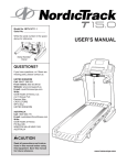
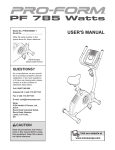
Model No. NTEVEX75911.0 Serial No. Write the serial number in the space above for reference. USER’S MANUAL Serial Number Decal QUESTIONS? If you have questions, or if there are missing parts, please contact us: UK Call: 08457 089 009 From Ireland: 053 92 36102 Website: www.iconsupport.eu E-mail: [email protected] Write: ICON Health & Fitness, Ltd. c/o HI Group PLC Express Way Whitwood, West Yorkshire WF10 5QJ, UK AUSTRALIA Call: 1-800-237-173 E-mail: [email protected] CAUTION Read all precautions and instructions in this manual before using this equipment. Keep this manual for future reference. www.iconeurope.com TABLE OF CONTENTS WARNING DECAL PLACEMENT . . . . . . . . . . . . . . . . . . . . . . . . . . . . . . . . . . . . . . . . . . . . . . . . . . . . . . . . . . . . . . .2 IMPORTANT PRECAUTIONS. . . . . . . . . . . . . . . . . . . . . . . . . . . . . . . . . . . . . . . . . . . . . . . . . . . . . . . . . . . . . . . . . . 3 BEFORE YOU BEGIN. . . . . . . . . . . . . . . . . . . . . . . . . . . . . . . . . . . . . . . . . . . . . . . . . . . . . . . . . . . . . . . . . . . . . . . .4 ASSEMBLY . . . . . . . . . . . . . . . . . . . . . . . . . . . . . . . . . . . . . . . . . . . . . . . . . . . . . . . . . . . . . . . . . . . . . . . . . . . . . . . .5 HOW TO USE THE EXERCISE BIKE . . . . . . . . . . . . . . . . . . . . . . . . . . . . . . . . . . . . . . . . . . . . . . . . . . . . . . . . . . .10 EXERCISE GUIDELINES. . . . . . . . . . . . . . . . . . . . . . . . . . . . . . . . . . . . . . . . . . . . . . . . . . . . . . . . . . . . . . . . . . . . 17 PART LIST. . . . . . . . . . . . . . . . . . . . . . . . . . . . . . . . . . . . . . . . . . . . . . . . . . . . . . . . . . . . . . . . . . . . . . . . . . . . . . . .18 EXPLODED DRAWING. . . . . . . . . . . . . . . . . . . . . . . . . . . . . . . . . . . . . . . . . . . . . . . . . . . . . . . . . . . . . . . . . . . . . .19 ORDERING REPLACEMENT PARTS . . . . . . . . . . . . . . . . . . . . . . . . . . . . . . . . . . . . . . . . . . . . . . . . . . . Back Cover RECYCLING INFORMATION. . . . . . . . . . . . . . . . . . . . . . . . . . . . . . . . . . . . . . . . . . . . . . . . . . . . . . . . . . Back Cover WARNING DECAL PLACEMENT This drawing shows the location(s) of the warning decal(s). If a decal is missing or illegible, see the front cover of this manual and request a free replacement decal. Apply the decal in the location shown. Note: The decal(s) may not be shown at actual size. NORDICTRACK is a registered trademark of ICON IP, Inc. 2 IMPORTANT PRECAUTIONS WARNING: To reduce the risk of serious injury, read all important precautions and instructions in this manual and all warnings on your exercise bike before using your exercise bike. ICON assumes no responsibility for personal injury or property damage sustained by or through the use of this product. 1. Before beginning any exercise program, consult your physician. This is especially important for persons over age 35 or persons with pre-existing health problems. 9. Wear appropriate clothes while exercising; do not wear loose clothes that could become caught on the exercise bike. Always wear athletic shoes for foot protection. 2. Use the exercise bike only as described in this manual. 10.The exercise bike should not be used by persons weighing more than 300 lbs. (136 kg). 3. It is the responsibility of the owner to ensure that all users of the exercise bike are adequately informed of all precautions. 11.Always keep your back straight while using the exercise bike; do not arch your back. 4. The exercise bike is intended for home use only. Do not use the exercise bike in a commercial, rental, or institutional setting. 12.The exercise bike does not have a freewheel; the pedals will continue to move until the flywheel stops. Reduce your pedaling speed in a controlled way. 5. Keep the exercise bike indoors, away from moisture and dust. Do not put the exercise bike in a garage or covered patio, or near water. 13.To stop the flywheel quickly, press the resistance knob downward. 14.When the exercise bike is not in use, tighten the resistance knob completely to prevent the flywheel from moving. 6. Place the exercise bike on a level surface, with a mat beneath it to protect the floor or carpet. Make sure that there is at least 2 ft. (0.6 m) of clearance around the exercise bike. 15.Over exercising may result in serious injury or death. If you feel faint or if you experience pain while exercising, stop immediately and cool down. 7. Inspect and properly tighten all parts regularly. Replace any worn parts immediately. 8. Keep children under age 12 and pets away from the exercise bike at all times. 3 BEFORE YOU BEGIN Thank you for selecting the new NORDICTRACK® GX 5.1 exercise bike. Cycling is an effective exercise for increasing cardiovascular fitness, building endurance, and toning the body. The GX 5.1 exercise bike provides a selection of features designed to make your workouts at home more effective and enjoyable. reading this manual, please see the front cover of this manual. To help us assist you, note the product model number and serial number before contacting us. The model number and the location of the serial number decal are shown on the front cover of this manual. Before reading further, please familiarize yourself with the parts that are labeled in the drawing below. For your benefit, read this manual carefully before you use the exercise bike. If you have questions after Length: 4 ft. 1 in. (124 cm) Width: 1 ft. 8 in. (51 cm) Weight:108 lbs. (49 kg) Console Handlebar Resistance Knob Handle Water Bottle Holder Adjustment Knob Seat Adjustment Knob Transmitter Wheel Pedal/Strap Leveling Foot Leveling Foot 4 ASSEMBLY Assembly requires two persons. Place all parts of the exercise bike in a cleared area and remove the packing materials. Do not dispose of the packing materials until assembly is completed. In addition to the included tool(s), assembly requires an adjustable wrench screwdriver . and a Phillips Note: If a part is not in the hardware kit, check to see if it has been preattached. 1. Remove the two screws, the two washers, and the shipping bracket (not shown) from the rear of the Frame (1) if necessary. Discard the screws, washers, and shipping bracket. Identify the Rear Stabilizer (58), which does not have wheels. Attach the Rear Stabilizer (58) to the Frame (1) with two M8 x 16mm Screws (55) and two M8 Washers (54). 1 55 54 1 58 2. Remove the two screws, the two washers, and the shipping bracket (not shown) from the front of the Frame (1) if necessary. Discard the screws, washers, and shipping bracket. 2 55 Attach the Front Stabilizer (49) to the Frame (1) with two M8 x 16mm Screws (55) and two M8 Washers (54). 54 1 49 5 3. Identify the Right Pedal (60), which is marked with an “R.” Using an adjustable wrench, firmly tighten the Right Pedal (60) clockwise into the Right Crank Arm (42). Tighten the Left Pedal (35) counterclockwise into the Left Crank Arm (36). 3 42 36 35 60 4. Orient the Handlebar Post (21) as shown. 4 Locate the Adjustment Knob (3) on the front of the Frame (1). Loosen the Adjustment Knob and pull it outward. Then, insert the Handlebar Post (21) into the Frame. 21 1 Move the Handlebar Post (21) upward or downward to the desired position, release the Adjustment Knob (3) into an adjustment hole in the Handlebar Post, and then tighten the Adjustment Knob. Make sure that the Adjustment Knob is firmly engaged in an adjustment hole. 5. Attach the Handlebar (22) to the Handlebar Post (21) with a Handle (25) and an M10 Washer (23). 3 5 22 Note: The Handle (25) functions like a ratchet. Turn the Handle clockwise, pull the Handle outward, turn the Handle counterclockwise, push the Handle inward, and then turn the Handle clockwise again. Repeat this process until the Handle is tight. 21 23 25 6 6. Orient the Seat Post (27) as shown. 6 Locate the Adjustment Knob (3) on the rear of the Frame (1). Loosen the Adjustment Knob and pull it outward. Then, insert the Seat Post (27) into the Frame. 27 3 Move the Seat Post (27) upward or downward to the desired position, release the Adjustment Knob (3) into an adjustment hole in the Seat Post, and then tighten the Adjustment Knob. Make sure that the Adjustment Knob is firmly engaged in an adjustment hole. 1 7. Orient the Seat (29) and the Seat Carriage (28) as shown. 7 24 Attach the Seat (29) to the Seat Carriage (28) with two M8 Hex Nuts (24). Make sure that the nose of the Seat is pointing straight ahead before you tighten the Hex Nuts. Note: The M8 Hex Nuts (24) may be preattached to the clamp on the Seat (29). Locate the Adjustment Knob (3) on the Seat Post (27). Loosen the Adjustment Knob and pull it outward. Then, insert the Seat Carriage (28) into the Seat Post. Slide the Seat Carriage (28) to the desired position and then release the Adjustment Knob (3) into one of the adjustment holes in the Seat Carriage. Make sure that the Adjustment Knob is firmly engaged in an adjustment hole. 29 24 28 27 3 8. Attach the Water Bottle Holder (6) to the Frame (1) with two M5 x 12mm Socket Screws (7). 8 7 7 6 1 9. The Console (63) requires two AAA batteries (not included); alkaline batteries are recommended. IMPORTANT: If the Console has been exposed to cold temperatures, allow it to warm to room temperature before you insert batteries. Otherwise, you may damage the console display or other electronic components. 9 Battery Compartment Remove the battery cover from the back of the Console (63), and insert batteries into the battery compartment. Make sure that the batteries are oriented as shown by the diagrams inside the battery compartment. Then, reattach the battery cover. 10.Attach the Console Bracket (66) to the Handlebar (22) with two Bracket Screws (64). Note: The Console Bracket may be preattached. 63 10 63 64 Then, attach the Console (63) to the Console Bracket (66) with a Console Screw (65). 65 66 22 8 64 11.The Transmitter (69) requires two AAA batteries (not included); alkaline batteries are recommended. 11 Remove the battery cover from the front of the Transmitter (69), and insert batteries into the battery compartment. Make sure that the batteries are oriented as shown by the diagrams inside the battery compartment. Then, reattach the battery cover. Remove the adhesive backing from the Hook and Loop Fasteners (68). Press a Fastener onto the Frame (1) in the indicated location. Orient the Transmitter (69) as shown. Press the other Fastener (68) onto the back of the Transmitter. Attach the Transmitter (69) to the Frame (1) using the Hook and Loop Fasteners (68). 69 1 12.Plug the Reed Switch (67) into the Transmitter (69). Insert the other end of the Reed Switch (67) into the Clamp (62). Rotate the Flywheel (33) until the Magnet (70) is aligned with the end of the Reed Switch (67). Move the Reed Switch (67) so that the gap between the Reed Switch and the Magnet (70) is about 1/8 in. (3 mm). Battery 68 Cover 12 33 70 62 69 67 13.Make sure that all parts are properly tightened before you use the exercise bike. Note: After assembly is completed, some extra parts may be left over. Place a mat beneath the exercise bike to protect the floor. 9 HOW TO USE THE EXERCISE BIKE HOW TO ADJUST THE ANGLE OF THE SEAT HOW TO ADJUST THE HORIZONTAL POSITION OF THE HANDLEBAR You can adjust the angle of the seat to the position that is most comfortable. You can also slide your seat forward or backward to increase your comfort or to adjust the distance to the handlebar. To adjust the horizontal position of the handlebar, loosen the handle, move the handlebar forward or backward to the desired position, and then tighten the handle. To adjust the seat, see the drawing in assembly step 7 on page 7. Loosen the nuts on the seat clamp a few turns, and then tilt the seat upward or downward or slide the seat forward or backward to the desired position. Then, retighten the nuts. HOW TO ADJUST THE HORIZONTAL POSITION OF THE SEAT To adjust the position of the seat, first Seat loosen the adjustment knob and pull it downward. Then, move the seat forward or backward, release the adjustAdjustment Knob ment knob into an adjustment hole in the seat carriage, and firmly tighten the adjustment knob. Make sure that the adjustment knob is engaged in an adjustment hole. Handlebar Handle Note: The handle functions like a ratchet. To loosen the handle, turn the handle counterclockwise, pull the handle outward, turn the handle clockwise, push the handle inward, and then turn the handle counterclockwise again. Reverse this process to tighten the handle. HOW TO ADJUST THE HANDLEBAR POST To adjust the height of the handlebar Handlebar post, first loosen the Post adjustment knob and pull it outward. Then, move the handlebar post upward or downward, release the Adjustment adjustment knob into Knob an adjustment hole in the handlebar post, and firmly tighten the adjustment knob. Make sure that the adjustment knob is engaged in an adjustment hole. HOW TO ADJUST THE SEAT POST For effective exercise, the seat should be at the proper height. As you pedal, there should be a slight bend in your knees when the pedals are in the lowest position. To adjust the height of the seat post, first loosen the adjustment knob and pull it outward. Then, Adjustment move the seat post Knob upward or downward, release the Seat adjustment knob into Post an adjustment hole in the seat post, and firmly tighten the adjustment knob. Make sure that the adjustment knob is engaged in an adjustment hole. 10 HOW TO ADJUST THE PEDAL STRAPS HOW TO LEVEL THE EXERCISE BIKE To tighten the pedal straps (see the drawing on page 4), simply pull the ends of the pedal straps. To loosen the pedal straps, press and hold the tabs on the buckles, adjust the pedal straps to the desired position, and then release the tabs. If the exercise bike rocks slightly on your floor during use, turn one or both of the leveling feet on the front or rear stabilizer (see the drawing on page 4) until the rocking motion is eliminated. HOW TO MAINTAIN THE EXERCISE BIKE HOW TO ADJUST THE PEDALING RESISTANCE To increase the resistance of the pedals, turn the resistance knob clockwise; to decrease the resistance, turn the resistance knob counterclockwise. Inspect and tighten all parts of the exercise bike regularly. Replace any worn parts immediately. To clean the exercise bike, use a damp cloth and a small amount of mild detergent. IMPORTANT: To avoid damage to the console, keep liquids away from the console and keep the console out of direct sunlight. Resistance Knob HOW TO ADJUST THE REED SWITCH If the console does not display correct feedback, the reed switch should be adjusted. To adjust the reed switch, see the drawing in assembly step 12 on page 9. To stop the flywheel, push the resistance knob downward. The flywheel should quickly come to a complete stop. Rotate the flywheel until the magnet is aligned with the reed switch. Slide the reed switch slightly toward or away from the magnet. Then, rotate the flywheel for a moment. Repeat these actions until the console displays correct feedback. IMPORTANT: When the exercise bike is not in use, tighten the resistance knob completely. 11 CONSOLE DIAGRAM HOW TO PERSONALIZE CONSOLE SETTINGS 1. Turn on the console. 98 rpm Press any button to turn on the console. 170 cals 175 cals 25 mph 2. Enter the setup mode. 20:28 time 7.8 dist First, press the Left button repeatedly until the word SPEED appears in the lower display. Then, press and hold the Right button for several seconds to enter the setup mode. Note: The console will exit the setup mode automatically if several seconds pass and no buttons are pressed. 3. Set a time goal if desired. Left Button When you enter the setup mode, the minutes place in the lower display will flash. Right Button FEATURES OF THE CONSOLE To set a time goal for your workout, press the Right button repeatedly to select the desired number of minutes. To select a time goal quickly, press and hold down the Right button. The console offers a selection of features designed to provide instant exercise feedback and make your workouts more effective. The console features a heart rate alarm that helps you keep your heart rate within your selected target heart rate zone while you exercise. Note: To use this feature, you must wear an optional heart rate monitor (see page 16). Note: You can set a time goal between 1 and 99 minutes. Note: If you set a time goal, the lower display will count down the time remaining in your workout instead of the elapsed time (see step 3 of HOW TO USE THE CONSOLE on page 14). The console also allows you to personalize settings, select a system of measurement, and enter user information before you begin exercising. To personalize console settings, see the instructions at the right. To set the clock, see page 14. To use the console, see page 14. To use the heart rate alarm, see page 16. Press the Left button to advance to the next setting. Before using the console, make sure that batteries are installed in the console and the transmitter (see assembly step 9 on page 8 and assembly step 11 on page 9). If there is a sheet of plastic on the display, remove the plastic. 12 7. 4. Define the target heart rate zone if desired. 6. Select a unit of measurement if desired. The maximum heart rate will flash in the middle left display. The console can display speed, distance, and weight in standard or metric measurements. The letters Lb (standard) or Kg (metric) will flash in the lower display to show which unit of measurement is selected. To set the maximum heart rate, press the Right button repeatedly to select the desired heart rate. To select a heart rate quickly, press and hold down the Right button. Press the Right button repeatedly to select the desired unit of measurement. Next, press the Left button. The minimum heart rate will flash in the middle left display. Press the Left button to advance to the next setting. 7. Enter your weight if desired. To set the minimum heart rate, press the Right button repeatedly to select the desired heart rate. To select a heart rate quickly, press and hold down the Right button. A weight setting will flash in the lower display. Note: You must define a target heart rate zone to use the heart rate alarm (see HOW TO USE THE HEART RATE ALARM on page 16). Press the Right button repeatedly to select your weight. To select your weight quickly, press and hold down the Right button. To determine your target heart rate zone, see EXERCISE INTENSITY on page 17. Press the Left button to advance to the next setting. Note: You can select a weight setting between 44 and 396 pounds or between 20 and 180 kilograms. The exercise bike should not be used by persons weighing more than 300 pounds or 136 kilograms. 5. Enter your gender if desired. A gender symbol will flash in the lower display. 8. Exit the setup mode at any time. The console will exit the setup mode automatically if several seconds pass and no buttons are pressed. Press the Right button repeatedly to select the symbol that represents your gender. Note: To advance again through the settings described in steps 3 to 7, press the Left button repeatedly. Press the Left button to advance to the next setting. 13 HOW TO SET THE CLOCK HOW TO USE THE CONSOLE 1. Turn on the console. 1. Turn on the console. Press any button to turn on the console. Press any button to turn on the console. 2. Enter the clock mode. 2. Wear an optional heart rate monitor if desired. First, press the Left button repeatedly until the clock symbol appears in the lower display. To display your heart rate (see step 3) or use the heart rate alarm (see HOW TO USE THE HEART RATE ALARM on page 16), you must wear an optional heart rate monitor (see page 16). 3.Follow your progress with the displays. Then, press and hold the Right button for several seconds to enter the clock mode. The upper left display— As you pedal, the rpm meter in this display indicates your approximate pedaling speed in revolutions per minute (rpm) in a range from 0 rpm to 200 rpm. Bars will appear or disappear in increments as you change your pedaling speed. Note: The console will exit the clock mode automatically if several seconds pass and no buttons are pressed. 3. Change the time notation if desired. The time notation will flash in the middle right display. The upper right display—This display shows your pedaling speed in revolutions per minute (rpm) in a range from 0 rpm to 240 rpm. Press the Right button repeatedly to select the desired time notation. Select 12H for a 12-hour clock. Select 24H for a 24-hour clock. Note: When you stop pedaling, this display shows the average pedaling speed (AVG rpm) for your workout. 4. Set the time. The middle left display—This display shows your heart rate (heart symbol) in beats per minute (bpm) in a range from 0 to 240 bpm when you wear an optional heart rate monitor (see page 16). Press the Left button to select the hour setting. The hour setting will flash in the lower display. Press the Right button repeatedly to select the desired hour setting. Make sure to select the correct am or pm setting when you select the hour setting. The middle right display—This display shows the approximate number of calories (KCAL) you have burned. Press the Left button to select the minute setting. The minute setting will flash in the lower display. Press the Right button repeatedly to select the desired minute setting. 5. Exit the clock mode at any time. The console will exit the clock mode automatically if several seconds pass and no buttons are pressed. 14 The lower display—This display can show the following workout information: To turn on the console backlight for a few seconds, press the Right button once at any time. Speed (SPEED)—This display shows your pedaling speed in miles per hour (ML/H) or kilometers per hour (KM/H). Note: The console can display speed and distance in either miles or kilometers. The letters ML/H or KM/H will appear in the display to show which unit of measurement is selected. To change the unit of measurement, see step 6 on page 13. Note: When you stop pedaling, this display shows the average pedaling speed (AVG SPEED) for your workout. 4. Set a time goal, if desired. Distance (DIST)—This display shows the distance you have pedaled in miles (ML) or kilometers (KM). To clear the time goal, press the Left button repeatedly until the word TIME appears in the lower display. Then, press and hold the Right button until zeros appear in the lower display. Note: If you set a time goal, the lower display will count down the time remaining in your workout instead of the elapsed time. Time (TIME)—This display shows the elapsed time in a range from 0 minutes to 99 minutes. When you reach your goal, a tone will sound for several seconds. Then, the console will begin to count the elapsed time. Note: If you set a time goal (see step 4), this display shows the time remaining in your workout instead of the elapsed time. To set a time goal, see step 3 on page 12. 5. Measure your heart rate if desired. To display your heart rate, you must wear an optional heart rate monitor (see page 16). lock (Clock symC bol)—This display shows the time of day using a 12-hour clock or a 24-hour clock. When your heart rate is detected, the heart symbol will flash and your heart rate will be shown in the middle left display. Press the Left button repeatedly until the lower display shows the workout information you are interested in viewing. 6.When you are finished exercising, the console will turn off automatically. To reset the displays, press the Left button repeatedly until the word TIME appears in the lower display. Then, press and hold the Right button until zeros appear in the displays. The console has an “auto-off” feature. If the pedals do not move and the buttons are not pressed for a few minutes, the power will turn off automatically to save the batteries. 15 HOW TO USE THE98 HEART rpm RATE ALARM 170 cals The heart rate alarm175 willcals alert you when your heart rate mph target heart rate zone. is below or above a25 defined 20:28 time 7.8 dist IMPORTANT: You must wear an optional heart rate monitor to use the heart rate alarm (see THE OPTIONAL HEART RATE MONITOR at the right). THE OPTIONAL HEART RATE MONITOR The optional heart rate monitor provides hands-free operation and continuously monitors your heart rate during your workouts. To purchase the optional heart rate monitor, see the front cover of this manual. To use the heart rate alarm, first see step 4 on page 13 and define a target heart rate zone. As you pedal, the console will regularly compare your heart rate to the target heart rate zone and will indicate if your heart rate is too far below or above the target heart rate zone. When a downward-pointing arrow flashes in the middle left display, increase your pedaling speed. When an upward-pointing arrow flashes in the middle left display, decrease your pedaling speed. IMPORTANT: The heart rate alarm is intended only to provide motivation. Make sure to pedal at a speed that is comfortable for you. 16 EXERCISE GUIDELINES Burning Fat—To burn fat effectively, you must exercise at a low intensity level for a sustained period of time. During the first few minutes of exercise, your body uses carbohydrate calories for energy. Only after the first few minutes of exercise does your body begin to use stored fat calories for energy. If your goal is to burn fat, adjust the intensity of your exercise until your heart rate is near the lowest number in your training zone. For maximum fat burning, exercise with your heart rate near the middle number in your training zone. WARNING: Before beginning this or any exercise program, consult your physician. This is especially important for persons over age 35 or persons with pre-existing health problems. The heart rate monitor is not a medical device. Various factors may affect the accuracy of heart rate readings. The heart rate monitor is intended only as an exercise aid in determining heart rate trends in general. Aerobic Exercise—If your goal is to strengthen your cardiovascular system, you must perform aerobic exercise, which is activity that requires large amounts of oxygen for prolonged periods of time. For aerobic exercise, adjust the intensity of your exercise until your heart rate is near the highest number in your training zone. These guidelines will help you to plan your exercise program. For detailed exercise information, obtain a reputable book or consult your physician. Remember, proper nutrition and adequate rest are essential for successful results. WORKOUT GUIDELINES EXERCISE INTENSITY Warming Up—Start with 5 to 10 minutes of stretching and light exercise. A warm-up increases your body temperature, heart rate, and circulation in preparation for exercise. Whether your goal is to burn fat or to strengthen your cardiovascular system, exercising at the proper intensity is the key to achieving results. You can use your heart rate as a guide to find the proper intensity level. The chart below shows recommended heart rates for fat burning and aerobic exercise. Training Zone Exercise—Exercise for 20 to 30 minutes with your heart rate in your training zone. (During the first few weeks of your exercise program, do not keep your heart rate in your training zone for longer than 20 minutes.) Breathe regularly and deeply as you exercise—never hold your breath. Cooling Down—Finish with 5 to 10 minutes of stretching. Stretching increases the flexibility of your muscles and helps to prevent post-exercise problems. EXERCISE FREQUENCY To find the proper intensity level, find your age at the bottom of the chart (ages are rounded off to the nearest ten years). The three numbers listed above your age define your “training zone.” The lowest number is the heart rate for fat burning, the middle number is the heart rate for maximum fat burning, and the highest number is the heart rate for aerobic exercise. To maintain or improve your condition, complete three workouts each week, with at least one day of rest between workouts. After a few months of regular exercise, you may complete up to five workouts each week, if desired. Remember, the key to success is to make exercise a regular and enjoyable part of your everyday life. 17 PART LIST Model No. NTEVEX75911.0 R0212A Key No. Qty. Description Key No. Qty. Description 1 2 3 4 5 6 7 8 9 10 11 12 13 14 15 16 17 18 19 20 21 22 23 24 25 26 27 28 29 30 31 32 33 34 35 36 37 Frame Sleeve Adjustment Knob M8 x 40mm Socket Bolt M8 Nut Water Bottle Holder M5 x 12mm Socket Screw Resistance Knob Short Spring 3/8" Square Nut Spacer Brake Shoe Black Acorn Nut Flange Nut Lever Bracket Brake Bracket M5 x 15mm Socket Screw M6 x 45mm Button Bolt M5 Washer M6 Locknut Handlebar Post Handlebar M10 Washer M8 Hex Nut Handle Carriage Cap Seat Post Seat Carriage Seat Hub Set Ring Small Pulley Flywheel Crank Cap Left Pedal/Strap Left Crank Arm Large Pulley 38 39 40 41 42 43 44 45 46 47 48 49 50 51 52 53 54 55 56 57 58 59 60 61 62 63 64 65 66 67 68 69 70 71 * * Outer Shield Drive Belt Inner Shield Front Shield Right Crank Arm M8 Locknut Split Washer M8 x 20mm Hex Bolt M8 x 10mm Hex Bolt M4 x 12mm Self-tapping Screw M5 x 12mm Screw Front Stabilizer Leveling Foot 3/8" Hex Nut Stabilizer Cap M8 x 45mm Socket Bolt M8 Washer M8 x 16mm Screw Wheel M6 Washer Rear Stabilizer Crank Screw Right Pedal/Strap Crank Hub Clamp Console Bracket Screw Console Screw Console Bracket Reed Switch Hook and Loop Fastener Transmitter Magnet Long Spring Assembly Tool User’s Manual 1 3 3 2 2 1 4 1 1 1 1 1 1 2 1 1 1 2 3 2 1 1 3 2 1 3 1 1 1 1 1 1 1 2 1 1 1 1 1 1 1 1 8 6 6 2 9 2 1 4 4 4 2 8 4 2 4 1 2 1 1 1 1 2 1 1 1 1 1 1 1 – – Note: Specifications are subject to change without notice. For information about ordering replacement parts, see the back cover of this manual. *These parts are not illustrated. 18 EXPLODED DRAWING Model No. NTEVEX75911.0 R0212A 22 24 63 64 29 65 66 24 28 64 8 23 2 26 21 3 25 2 3 26 7 6 14 9 10 11 19 17 20 26 27 71 23 23 13 16 57 15 57 32 57 57 12 30 7 53 35 34 55 51 3 5 36 1 55 40 19 54 58 50 51 19 52 51 53 14 70 56 31 39 51 50 67 45 54 54 52 50 48 61 52 33 54 49 68 4 43 54 52 59 56 54 18 69 2 54 47 46 42 48 45 44 37 50 59 34 44 47 19 47 47 62 43 47 43 38 47 41 47 60 ORDERING REPLACEMENT PARTS To order replacement parts, please see the front cover of this manual. To help us assist you, be prepared to provide the following information when contacting us: • the model number and serial number of the product (see the front cover of this manual) • the name of the product (see the front cover of this manual) • the key number and description of the replacement part(s) (see the PART LIST and the EXPLODED DRAWING near the end of this manual) RECYCLING INFORMATION This electronic product must not be disposed of in municipal waste. To preserve the environment, this product must be recycled after its useful life as required by law. Please use recycling facilities that are authorized to collect this type of waste in your area. In doing so, you will help to conserve natural resources and improve European standards of environmental protection. If you require more information about safe and correct disposal methods, please contact your local city office or the establishment where you purchased this product. Part No. 317581 R0212A Printed in China © 2011 ICON IP, Inc.