1
UM0721
User manual
STM32F105xx and STM32F107xx USB on-the-go (OTG) FS library
Introduction
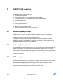
The USB OTG FS library is a firmware package supporting the USB on-the-go (OTG) fullspeed (FS) peripheral of the STM32F105xx and STM32F107xx connectivity line
microcontrollers. It provides a low-level driver to easily connect any USB stack, plus a rich
set of demonstrations available in binary format.
This user manual presents a description of all the components of the
STM32F105xx/STM32F107xx USB OTG FS library:
●
USB OTG FS Core
●
Low-level driver
Host device and OTG - DRD (dual role device) demonstrations
June 2009
Doc ID 15857 Rev 1
1/35
www.st.com
Contents
UM0721
Contents
1
Glossary . . . . . . . . . . . . . . . . . . . . . . . . . . . . . . . . . . . . . . . . . . . . . . . . . . . 6
2
Related documents . . . . . . . . . . . . . . . . . . . . . . . . . . . . . . . . . . . . . . . . . . 7
3
USB OTG FS overview . . . . . . . . . . . . . . . . . . . . . . . . . . . . . . . . . . . . . . . 8
4
5
3.1
Session request protocol . . . . . . . . . . . . . . . . . . . . . . . . . . . . . . . . . . . . . . 8
3.2
Host negotiation protocol . . . . . . . . . . . . . . . . . . . . . . . . . . . . . . . . . . . . . . 8
3.3
OTG descriptor . . . . . . . . . . . . . . . . . . . . . . . . . . . . . . . . . . . . . . . . . . . . . . 8
3.4
SetFeature command . . . . . . . . . . . . . . . . . . . . . . . . . . . . . . . . . . . . . . . . . 9
3.5
OTG device state machine . . . . . . . . . . . . . . . . . . . . . . . . . . . . . . . . . . . . 10
STM32F105xx/STM32F107xx USB OTG FS interface . . . . . . . . . . . . . . 12
4.1
Features . . . . . . . . . . . . . . . . . . . . . . . . . . . . . . . . . . . . . . . . . . . . . . . . . . 12
4.2
USB hardware connections . . . . . . . . . . . . . . . . . . . . . . . . . . . . . . . . . . . 14
USB OTG FS low-level driver . . . . . . . . . . . . . . . . . . . . . . . . . . . . . . . . . 16
5.1
6
2/35
Driver architecture . . . . . . . . . . . . . . . . . . . . . . . . . . . . . . . . . . . . . . . . . . 16
5.1.1
Core interface layer (CIL) . . . . . . . . . . . . . . . . . . . . . . . . . . . . . . . . . . . . 16
5.1.2
Peripheral controller driver (PCD) . . . . . . . . . . . . . . . . . . . . . . . . . . . . . 16
5.1.3
Host controller driver (HCD) . . . . . . . . . . . . . . . . . . . . . . . . . . . . . . . . . 16
5.1.4
OTG controller driver (OTG) . . . . . . . . . . . . . . . . . . . . . . . . . . . . . . . . . 16
5.2
OTG controller configuration . . . . . . . . . . . . . . . . . . . . . . . . . . . . . . . . . . 16
5.3
Driver interfacing . . . . . . . . . . . . . . . . . . . . . . . . . . . . . . . . . . . . . . . . . . . 17
5.4
Driver integration . . . . . . . . . . . . . . . . . . . . . . . . . . . . . . . . . . . . . . . . . . . 17
5.5
Core initialization . . . . . . . . . . . . . . . . . . . . . . . . . . . . . . . . . . . . . . . . . . . 17
5.5.1
Common initialization: . . . . . . . . . . . . . . . . . . . . . . . . . . . . . . . . . . . . . . 17
5.5.2
Device initialization . . . . . . . . . . . . . . . . . . . . . . . . . . . . . . . . . . . . . . . . 18
5.5.3
Host initialization . . . . . . . . . . . . . . . . . . . . . . . . . . . . . . . . . . . . . . . . . . 18
5.5.4
Device programming model . . . . . . . . . . . . . . . . . . . . . . . . . . . . . . . . . . 19
5.5.5
Host programming model . . . . . . . . . . . . . . . . . . . . . . . . . . . . . . . . . . . . 20
5.5.6
OTG programming model . . . . . . . . . . . . . . . . . . . . . . . . . . . . . . . . . . . 21
USB OTG FS demonstration description . . . . . . . . . . . . . . . . . . . . . . . 23
Doc ID 15857 Rev 1
UM0721
Contents
6.1
Introduction . . . . . . . . . . . . . . . . . . . . . . . . . . . . . . . . . . . . . . . . . . . . . . . 23
6.1.1
Hardware requirements . . . . . . . . . . . . . . . . . . . . . . . . . . . . . . . . . . . . . 23
6.1.2
Jumper settings . . . . . . . . . . . . . . . . . . . . . . . . . . . . . . . . . . . . . . . . . . . 24
6.2
Firmware architecture overview . . . . . . . . . . . . . . . . . . . . . . . . . . . . . . . . 24
6.3
USB Device mode demonstrations . . . . . . . . . . . . . . . . . . . . . . . . . . . . . 25
6.4
USB Host mode demonstrations . . . . . . . . . . . . . . . . . . . . . . . . . . . . . . . 26
6.5
USB OTG dual role device demonstration . . . . . . . . . . . . . . . . . . . . . . . . 29
6.5.1
Hardware configuration . . . . . . . . . . . . . . . . . . . . . . . . . . . . . . . . . . . . . 29
6.5.2
HyperTerminal settings . . . . . . . . . . . . . . . . . . . . . . . . . . . . . . . . . . . . . 29
6.5.3
Demo description . . . . . . . . . . . . . . . . . . . . . . . . . . . . . . . . . . . . . . . . . . 29
6.5.4
Starting SRP requests . . . . . . . . . . . . . . . . . . . . . . . . . . . . . . . . . . . . . . 30
6.5.5
Starting HNP requests . . . . . . . . . . . . . . . . . . . . . . . . . . . . . . . . . . . . . . 31
7
USB OTG FS demonstration package . . . . . . . . . . . . . . . . . . . . . . . . . . 32
8
Revision history . . . . . . . . . . . . . . . . . . . . . . . . . . . . . . . . . . . . . . . . . . . 34
Doc ID 15857 Rev 1
3/35
List of tables
UM0721
List of tables
Table 1.
Table 2.
Table 3.
Table 4.
Table 5.
Table 6.
4/35
List of acronyms . . . . . . . . . . . . . . . . . . . . . . . . . . . . . . . . . . . . . . . . . . . . . . . . . . . . . . . . . . 6
OTG descriptor . . . . . . . . . . . . . . . . . . . . . . . . . . . . . . . . . . . . . . . . . . . . . . . . . . . . . . . . . . . 9
SetFeature command . . . . . . . . . . . . . . . . . . . . . . . . . . . . . . . . . . . . . . . . . . . . . . . . . . . . . . 9
Feature selector values . . . . . . . . . . . . . . . . . . . . . . . . . . . . . . . . . . . . . . . . . . . . . . . . . . . . 9
Required jumper configuration . . . . . . . . . . . . . . . . . . . . . . . . . . . . . . . . . . . . . . . . . . . . . . 24
Document revision history . . . . . . . . . . . . . . . . . . . . . . . . . . . . . . . . . . . . . . . . . . . . . . . . . 34
Doc ID 15857 Rev 1
UM0721
List of figures
List of figures
Figure 1.
Figure 2.
Figure 3.
Figure 4.
Figure 5.
Figure 6.
Figure 7.
Figure 8.
Figure 9.
Figure 10.
Figure 11.
Figure 12.
Figure 13.
Figure 14.
Figure 15.
Figure 16.
Figure 17.
Figure 18.
B-Device state machine . . . . . . . . . . . . . . . . . . . . . . . . . . . . . . . . . . . . . . . . . . . . . . . . . . . 10
A-Device state machine . . . . . . . . . . . . . . . . . . . . . . . . . . . . . . . . . . . . . . . . . . . . . . . . . . . 11
USB OTG FS interface . . . . . . . . . . . . . . . . . . . . . . . . . . . . . . . . . . . . . . . . . . . . . . . . . . . . 13
USB device mode connection. . . . . . . . . . . . . . . . . . . . . . . . . . . . . . . . . . . . . . . . . . . . . . . 14
USB host mode connection . . . . . . . . . . . . . . . . . . . . . . . . . . . . . . . . . . . . . . . . . . . . . . . . 15
Driver architecture overview . . . . . . . . . . . . . . . . . . . . . . . . . . . . . . . . . . . . . . . . . . . . . . . . 16
Driver file . . . . . . . . . . . . . . . . . . . . . . . . . . . . . . . . . . . . . . . . . . . . . . . . . . . . . . . . . . . . . . 17
STM3210C-EVAL board . . . . . . . . . . . . . . . . . . . . . . . . . . . . . . . . . . . . . . . . . . . . . . . . . . . 23
Demo firmware layers . . . . . . . . . . . . . . . . . . . . . . . . . . . . . . . . . . . . . . . . . . . . . . . . . . . . . 24
USB Device mass storage demonstration . . . . . . . . . . . . . . . . . . . . . . . . . . . . . . . . . . . . . 25
USB Device HID demonstration . . . . . . . . . . . . . . . . . . . . . . . . . . . . . . . . . . . . . . . . . . . . . 25
USB Host mass storage demonstration . . . . . . . . . . . . . . . . . . . . . . . . . . . . . . . . . . . . . . . 26
USB Host HID host demonstration . . . . . . . . . . . . . . . . . . . . . . . . . . . . . . . . . . . . . . . . . . . 27
USB Host mass storage with audio support demonstration . . . . . . . . . . . . . . . . . . . . . . . . 28
Dual role device hardware configuration . . . . . . . . . . . . . . . . . . . . . . . . . . . . . . . . . . . . . . 29
SRP start menu . . . . . . . . . . . . . . . . . . . . . . . . . . . . . . . . . . . . . . . . . . . . . . . . . . . . . . . . . 30
SRP host mode menu. . . . . . . . . . . . . . . . . . . . . . . . . . . . . . . . . . . . . . . . . . . . . . . . . . . . . 31
USB OTG demonstration package directories . . . . . . . . . . . . . . . . . . . . . . . . . . . . . . . . . . 32
Doc ID 15857 Rev 1
5/35
Glossary
1
UM0721
Glossary
Table 1.
6/35
List of acronyms
CIL
Core interface layer
DRD
Dual role device
FS
Full-speed
IP
Intellectual property
HCD
Host controller driver
HNP
Host negotiation protocol
MSC
Mass storage class
OSI
Open system interconnection
OTG
USB on-the-go
PCD
Peripheral controller driver
PHY
Physical layer as described in the OSI model
RTOS
Real-time operating system
SRP
Session request protocol
USB
Universal serial bus
µC
Microcontroller
Doc ID 15857 Rev 1
UM0721
2
Related documents
Related documents
●
DesignWare Cores Hi-Speed USB On-The-Go (OTG) Controller Subsystem Data book
●
On-The-Go Supplement to the USB 2.0 Specification Revision 1.3
●
Universal Serial Bus Specification, Revision 2.0
Doc ID 15857 Rev 1
7/35
USB OTG FS overview
3
UM0721
USB OTG FS overview
In addition to being a fully compliant USB 2.0 peripheral, an on-the-go device must include
the following features and characteristics:
3.1
●
A limited Host capability
●
Full-speed operation as a peripheral (high-speed optional)
●
Full-speed support as a Host (low-speed and high-speed optional)
●
Targeted peripheral list
●
Session request protocol
●
Host negotiation protocol
●
One and only one connection: a Micro-AB receptacle
●
Minimum of 8 mA output on VBUS
●
Means for communicating messages to the user
Session request protocol
The Session Request Protocol (SRP) allows a B-device to request the A-device to turn on
VBUS and start a session. This protocol allows the A-device, which may be battery
powered, to conserve power by turning VBUS off when there is no bus activity while still
providing a means for the B-device to initiate bus activity.
Any A-device, including a PC or laptop, is allowed to respond to SRP. Any B-device,
including a standard USB peripheral, is allowed to initiate SRP. An On-The-Go device is
required to be able to initiate and respond to SRP.
3.2
Host negotiation protocol
The Host Negotiation Protocol (HNP) allows the Host function to be transferred between two
directly connected On-The-Go devices and eliminates the need for a user to switch the
cable connections in order to allow a change in control of communications between the
devices. HNP will typically be initiated in response to input from the user or an Application
on the On-The-Go B-device. HNP may only be implemented through the Micro-AB
receptacle on a device.
3.3
OTG descriptor
During enumeration, an On-The-Go A-device must request the OTG configuration
descriptor from the B-device. Any B-device that supports either HNP or SRP must respond
by providing this descriptor in the group of descriptors returned in response to a
GetDescriptor (Configuration) command. When present, the OTG descriptor must be
present in all configurations. This three-byte descriptor consists of three fields: bLength,
bDescriptorType, and bmAttributes, with bits as defined in Table 2.
8/35
Doc ID 15857 Rev 1
UM0721
USB OTG FS overview
Table 2.
OTG descriptor
Offset
Size
Value
Description
0
blength
1
Number (3)
Size of descriptor
1
bDescriptorType
1
Constant
OTG type = 9
Bitmap
Attribute fields
D7.. 2: Reserved (rest to zero)
D1: HNP support
D0: SRP support
2
3.4
Field
bmAttributes
1
SetFeature command
An A-device may use the SetFeature command to configure the B-device or to indicate
certain capabilities of the A-device to the B-device. Any HNP capable device is required to
accept the SetFeature commands for these features.
If the device is not HNP capable, it must return STALL if it receives a SetFeature command
for any of these features. A B-device that supports HNP features must be able to accept the
SetFeature command in the Default, Address and Configured states.
Note:
The USB 2.0 specification [USB2.0] does not specify features other than test mode that can
be requested by the SetFeature command when the Device is in the Default state. The OTG
supplement adds to the list of features that can be set in the Default state.
Setting one of these features when it is already set is not an error. The device receiving such
a command will acknowledge the command indicating successful completion.
A SetFeature command for these features must be executed on receipt of an uncorrupted
command packet.
Table 3.
SetFeature command
bmRequestType
bRequest
wValue
wIndex
wLength
Data
00000000B
SET_FEATURE
Feature
Selector
Zero
Zero
None
Table 4.
Feature selector values
Feature Selector
Values
b_hnp_enable
3
a_hnp_support
4
a_alt_hnp_support
5
Doc ID 15857 Rev 1
9/35
USB OTG FS overview
3.5
OTG device state machine
Figure 1.
10/35
UM0721
B-Device state machine
Doc ID 15857 Rev 1
UM0721
USB OTG FS overview
Figure 2.
A-Device state machine
Doc ID 15857 Rev 1
11/35
STM32F105xx/STM32F107xx USB OTG FS interface
4
UM0721
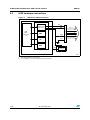
STM32F105xx/STM32F107xx USB OTG FS interface
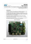
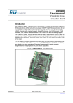
The USB OTG FS peripheral is one of the major peripherals embedded in STM32
Connectivity line microcontrollers, it is a dual-role device (DRD) controller that supports both
device and host functions and is fully compliant with the On-The-Go Supplement to the USB
2.0 Specification. It can also be configured as a host-only or device-only controller, fully
compliant with the USB 2.0 Specification. In host mode, the OTG FS supports full-speed
(FS, 12 Mbits/s) and low-speed (LS, 1.5 Mbits/s) transfers whereas in device mode, it only
supports full-speed (FS, 12 Mbits/s) transfers. The OTG FS supports both HNP and SRP.
The only external device required is a charge pump for VBUS in Host mode.
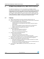
4.1
Features
●
USB-IF certified compliant with Universal Serial Bus Specification Rev 2.0
●
Includes full support (PHY) for the optional On-The-Go (OTG) protocol as described in
the On-The-Go Supplement Rev 1.3 specification
●
●
Integrated support for A-B Device Identification (ID line)
–
Integrated support for Host Negotiation Protocol (HNP) and Session Request
Protocol (SRP)
–
Allows host to turn VBUS off to conserve battery power in OTG applications
–
Supports OTG monitoring of VBUS levels with internal comparators
–
Supports dynamic Host-Peripheral role switching
Software-configurable as:
–
SRP-capable USB FS Peripheral (B-Device)
–
SRP-capable USB FS/LS Host (A-Device)
–
USB On-The-Go Full-Speed Dual Role Device
Supports FS SOF and LS Keep-alives with:
–
SOF pulse PAD connectivity
–
SOF pulse internal connection to timer2 (TIM2)
–
Configurable framing period and end of frame interrupt threshold
●
Includes power saving features such as system stop during USB Suspend, optional
switch-off of internal clock domains, PHY and data FIFO power management
●
Dedicated 1.25 Kbyte RAM with advanced FIFO control:
●
12/35
–
–
Configurable partitioning in different FIFOs for flexible and efficient use of RAM
–
Each FIFO can hold multiple packets
–
Dynamic memory allocation and configurable FIFO sizes (not limited to powers of
2 to allow the use of contiguous memory locations)
Guaranteed max. USB bandwidth for up to one frame (1ms) without system
intervention
Doc ID 15857 Rev 1
UM0721
STM32F105xx/STM32F107xx USB OTG FS interface
USB OTG FS interface
AHB peripheral bus
Power
and
clock
control
Cortex M3
USB interrupt
USB 2.0
OTG FS
core
DP
UTMIFS
USB suspend
USB Clock @ 48 MHz System clock
domain
USB clock
domain
OTG FS
PHY
DM
ID
VBUS
UNIVERSAL SERIAL
BUS
RAMbus
Figure 3.
1.25 Kbyte
USB data
FIFOs
Doc ID 15857 Rev 1
13/35
STM32F105xx/STM32F107xx USB OTG FS interface
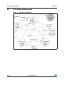
4.2
UM0721
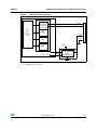
USB hardware connections
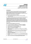
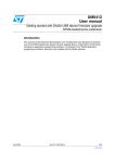
Figure 4.
USB device mode connection
STM32F105xx/STM32F107xx
OTG PHY
USB
OTG
Full-speed
core
DM
HNP
V BUS
VSS
ID
USB Micro-B connector
DP
USB
Full-speed
transceiver
To host
DP
DM
VBUS
VSS
SRP
VDD(1)
5 V to VDD
Regulator(2)
ai15653b
1. VDD ranges between 2 V and 3.6 V.
2. Use a regulator if you want to build a bus-powered device.
14/35
Doc ID 15857 Rev 1
UM0721
STM32F105xx/STM32F107xx USB OTG FS interface
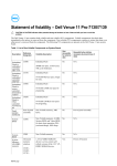
Figure 5.
USB host mode connection
STM32F105xx/STM32F107xx
OTG PHY
USB
OTG
Full-speed
core
DM
HNP
V BUS
VSS
ID
USB Std-A connector
DP
USB
full-speed/
low-speed
transceiver
VDD(2)
SRP
GPIO
GPIO + IRQ
Current-limited
power distribution 5 V
switch
OVRCR
STMPS2141STR(1)
flag
EN
ai15654b
1. STMPS2141STR needed only if the application has to support bus-powered devices.
2. VDD ranges between 2 V and 3.6 V.
Doc ID 15857 Rev 1
15/35
USB OTG FS low-level driver
UM0721
5
USB OTG FS low-level driver
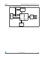
5.1
Driver architecture
Figure 6.
Driver architecture overview
Host
OTG
Device
HCD
PCD
(usb_hcd.c/h)
(usb_pcd.c/h)
Upper layer: stack and high
level software
Low level driver
CIL (Core Interface Layer)
(usb_core.c/h)
5.1.1
Core interface layer (CIL)
This layer provides common APIs for device, host and OTG modes: the core initialization in
each mode and the control of the transfer flow.
5.1.2
Peripheral controller driver (PCD)
This layer provides an API for device mode access and the main interrupt routine for this
mode.
5.1.3
Host controller driver (HCD)
This layer provides an API for host mode access and the main interrupt routine for this
mode.
5.1.4
OTG controller driver (OTG)
This layer provides an API for OTG mode access and the main interrupt routine for this
mode.
5.2
OTG controller configuration
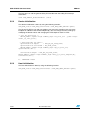
The configuration of the low level driver is done using the usb_conf.h file
#define DUAL_ROLE_MODE_ENABLED: Select dual role mode (OTG)
#define HOST_MODE_ENABLED: Select Host mode only
#define DEVICE_MODE_ENABLED: Select Device mode only
Note:
16/35
1
The USB mode must be selected by using one of the above listed defines.
2
When DUAL_ROLE_MODE_ENABLED mode is selected HOST_MODE_ENABLED and
DEVICE_MODE_ENABLED are automatically selected.
Doc ID 15857 Rev 1
UM0721
5.3
USB OTG FS low-level driver
Driver interfacing
The low level driver connects the USB OTG FS core with the high level USB OTG stack.
To interface the low level driver with a specific stack, a user-developed interface layer may
be used to provide the required APIs.
5.4
Driver integration
Figure 7.
Driver file
To integrate the driver in an application:
●
Include the library files needed by the project
●
Exclude any unused layers
●
Then, configure the library by modifying the usb_conf.h file according to the features
that are used (see Section 5.2)
5.5
Core initialization
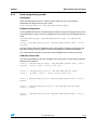
5.5.1
Common initialization:
To use the USB OTG FS core the driver must be initialized by setting the start address of the
core structure. This by calling the following function declared in the usb_core.c.:
USB_OTG_Status USB_OTG_SetAddress (USB_OTG_CORE_DEVICE *pdev,
uint32_t BaseAddress);
The BaseAddress is defined in the usbh_regs.h file.
Then the core is configured by the USB_OTG_core_cfg structure through the function:
USB_OTG_Status USB_OTG_CoreInit (USB_OTG_CORE_DEVICE *pdev)
/* Initialialize the base address of the memory-mapped registers */
USB_OTG_SetAddress(pdev, USB_OTG_FS1_BASE_ADDR);
/* Disable the global interrupt in AHB Configuration register */
USB_OTG_DisableGlobalInt(pdev);
/* Initialize all the required registers for the Core */
USB_OTG_CoreInit(pdev)
(...)
USB_OTG_EnableGlobalInt(pdev)
Doc ID 15857 Rev 1
17/35
USB OTG FS low-level driver
UM0721
The last step is to call the general USB_OTG handler from the USB_OTG interrupt
subroutine:
void USB_OTGFS1_GlobalHandler (void)
5.5.2
Device initialization
The device initialization is done by using the following function:
USB_OTG_Status USB_OTG_CoreInitDev (USB_OTG_CORE_DEVICE *pdev)
The Rx and Tx FIFOs size and start address are set by this function to use one more
Endpoint in addition to the control Endpoint (0). You can change the FIFO settings by
modifying the default values and changing the FIFO depth for each Tx FIFO.
/* set Rx FIFO size */
WRITE_REG32( &pdev->regs.common_regs->rx_fifo_siz , pdev->cfgs>host_rx_fifo_size);
/* Non-periodic Tx FIFO */
nptxfifosize.b.depth
= DEV_NP_TX_FIFO_SIZE;
nptxfifosize.b.startaddr = RX_FIFO_SIZE;
WRITE_REG32( &pdev->regs.common_regs->np_tx_fifo_siz,
nptxfifosize.d32 );
txfifosize.b.depth = DEV_NP_TX_FIFO_SIZE;
WRITE_REG32( &pdev->regs.common_regs->dev_p_tx_fsiz_dieptxf[N],
txfifosize.d32 );
N : ENDPOINT index
5.5.3
Host initialization
The host initialization is done by using the following function:
USB_OTG_Status USB_OTG_CoreInitHost (USB_OTG_CORE_DEVICE *pdev)
18/35
Doc ID 15857 Rev 1
UM0721
5.5.4
USB OTG FS low-level driver
Device programming model
Initialization
When the USB OTG FS driver is called in device mode only, the core and device
initialization are done in the usb_pcd.c file by:
void USB_OTG_USBD_Init (USB_OTG_CORE_DEVICE *pdev)
Endpoint configuration
Once the USB OTG FS core is initialized, device mode is selected. The upper layer may call
the low level driver to open or close an Endpoint to start transfer. The two following APIs are
used:
USB_OTG_USBD_EP_Open (USB_OTG_CORE_DEVICE *pdev, EP_DESCRIPTOR
*epdesc)
uint32_t USB_OTG_USBD_EP_Close (USB_OTG_CORE_DEVICE *pdev, uint8_t
ep_addr)
The first function retrieves the Endpoint settings (EP address, direction, Transfer type and
Max Data transfer) from the epdesc structure and configures the addressed Endpoint.
The second function disables the already activated Endpoint after finishing the transfer.
USB data transfer flow
The PCD layer provides all the APIs needed to start and control a transfer flow through the
following set of functions:
uint32_t USB_OTG_USBD_EP_Read ( USB_OTG_CORE_DEVICE *pdev, uint8_t
ep_addr, uint8_t *pbuf, uint32_t buf_len);
uint32_t
uint8_t
USB_OTG_USBD_EP_Write (USB_OTG_CORE_DEVICE *pdev,
ep_addr, uint8_t *pbuf, uint32_t buf_len);
uint32_t USB_OTG_USBD_EP_Stall (USB_OTG_CORE_DEVICE *pdev, uint8_t
epnum);
uint32_t USB_OTG_USBD_EP_ClrStall (USB_OTG_CORE_DEVICE *pdev,
uint8_t epnum);
uint32_t USB_OTG_USBD_EP_Flush (USB_OTG_CORE_DEVICE *pdev, uint8_t
epnum);
Doc ID 15857 Rev 1
19/35
USB OTG FS low-level driver
UM0721
USB device interrupt subroutine
Following the selected mode in the usb_conf.h (see Section 5.2) the main ISR calls the
corresponding ISR handler:
void USB_OTGFS1_GlobalHandler (void)
You must modify the ISR subroutines to use the APIs given by the upper layer.
Example: In the end of transfer of an OUT EP, call the upper layer to receive or decode the
received data.
static uint32_t USB_OTG_USBD_HandleOutEP_ISR(USB_OTG_CORE_DEVICE
*pdev)
{
(..)
if ( doepint.b.xfercompl )
{
/* Clear the bit in DOEPINTn for this interrupt */
CLEAR_OUT_EP_INTR(epnum, xfercompl);
/* Inform upper layer: data ready */
!!!!! CODE TO BE ADDED BY USER !!!!!
}
(...)
}
5.5.5
Host programming model
Initialization
When the USB OTG FS driver is called in host mode only, the core and host initialization are
done in the usb_hcd.c file by:
void HOST_Init (USB_OTG_CORE_DEVICE *pdev).
Host channel initialization
To prepare and initialize a host channel for transfer, use the following function:
HOST_ChannelInit (USB_OTG_CORE_DEVICE *pdev, USB_OTG_HC
*pHostChannel)
Starting transfer
The upper layer must have a process to start a transfer on the activated host channel, for
example to submit the USB request block (URB) to the host channel.
The Submit URB could call the following function to start the process:
uint32_t HOST_StartXfer (USB_OTG_CORE_DEVICE *pdev, USB_OTG_HC
*pHostChannel)
20/35
Doc ID 15857 Rev 1
UM0721
USB OTG FS low-level driver
USB host device interrupt subroutine
Depending on the selected mode in the usb_conf.h (see Section 5.2) the main ISR calls the
corresponding ISR handler:
void USB_OTGFS1_GlobalHandler (void)
You must modify the ISR subroutines to use the APIs given by the upper layer.
5.5.6
OTG programming model
Initialization
OTG feature support is enabled once the core is initialized if the
DUAL_ROLE_MODE_ENABLED define has been uncommented in the usb_conf.h file.
These elementary functions can then be used to initiate the default mode:
USB_OTG_Status USB_OTG_CoreInitHost (USB_OTG_CORE_DEVICE *pdev)
USB_OTG_Status USB_OTG_CoreInitDev (USB_OTG_CORE_DEVICE *pdev)
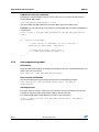
Starting SRP protocol
To initiate the session request protocol use this call:
void USB_OTG_InitiateSRP(void)
Starting HNP protocol
To initiate the session host negotiation protocol use this call:
void USB_OTG_InitiateHNP (uint8_t state, uint8_t mode)
Where state is 0 to deactivate, 1 to activate and mode is the current role mode (device or
host).
Doc ID 15857 Rev 1
21/35
USB OTG FS low-level driver
UM0721
USB Host device interrupt subroutine
Depending on the selected mode in the usb_conf.h (see Section 5.2) the main ISR calls the
corresponding ISR handler:
void USB_OTGFS1_GlobalHandler (void)
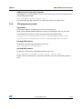
OTG event control
The USB OTG FS core informs the upper layer of the success or failure of the SRP or HNP
and also of any change to the ID line status in the OTG ISR. You must implement callbacks
to tie these events into the OTG stacks.
Example
static uint32_t USB_OTG_HandleConnectorIDStatusChange_ISR(void)
{
(....)
if (gotgctl.b.conidsts) // micro B connector
{
USB_OTG_DisableGlobalInt(&otgfs_dev1);
USB_OTG_CoreInitDev(&otgfs_dev1);
USB_OTG_EnableGlobalInt(&otgfs_dev1);
// INFORM UPPER LAYER
otgfs_dev1.OTG_State = B_PERIPHERAL;
}
else
{
USB_OTG_DisableGlobalInt(&otgfs_dev1);
USB_OTG_CoreInitHost(&otgfs_dev1);
USB_OTG_EnableGlobalInt(&otgfs_dev1);
// INFORM UPPER LAYER ;
otgfs_dev1.OTG_State = A_HOST;
}
(....)
}
22/35
Doc ID 15857 Rev 1
UM0721
USB OTG FS demonstration description
6
USB OTG FS demonstration description
6.1
Introduction
All the USB demonstration applications are designed for the STM3210C-EVAL board and
use the following firmware components:
●
STM32F10xxx standard peripheral drivers
●
uC-OSII RTOS v 2.86
●
uC-USB Host stack v3.0
●
uC-USB Device stack v3.0
●
uC-USB OTG stack v3.0
●
File System emFile V4.16 from Segger
●
MPEG audio decoder libmad 0.15.1b
The demonstration applications are provided in binary format.
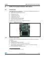
Figure 8.
6.1.1
STM3210C-EVAL board
Hardware requirements
The demonstration is designed for the STM3210C-Eval board and requires the following
accessories:
●
USB Flash disk(a)
●
Headphone with male jack connector
●
For device demos, a Micro-B to Standard-A plug cable(a)
●
For host demos, a Micro-A to Standard-A receptacle(a) (host mode is forced by
software and not by USB ID line)
●
For OTG mode demos, a Micro-AB cable(a)
a. Included in the STM3210C-EVAL board package.
Doc ID 15857 Rev 1
23/35
USB OTG FS demonstration description
6.1.2
UM0721
Jumper settings
The jumpers on the STM3210C-Eval board should be configured as follows:
Table 5.
Required jumper configuration
Jumper
6.2
Usage
Configuration
JP17
I2C
Fitted
SW1
Boot
1<->2
SW2
Boot
1<->2
JP26
SD Card detect
fitted
JP15
SD CS
fitted
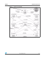
Firmware architecture overview
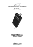
Figure 9.
Demo firmware layers
Applications
Audio codecs + high level software components
µC/USB Stack
Host
OTG
HC APIs
Device
OTG
APIs
HCD
Device
APIs
BSP
RTOS (µCOS II)
File system
stack
PCD
CIL (Core interface layer )
USB OTG FS core
StdFwLib
ai15701
The applications with the USB OTG FS core are built using the architecture shown in
Figure 9.
24/35
●
The RTOS (uC-OS-II) is used to control the uC-USB stack internal machine, application
tasks and internal flow (events).
●
The uC-USB stack (device, host and OTG) is interfaced with the generic low level driver
to provide access to the USB core.
●
The file system is used when the Host mass storage demo is running to translate the
logical addresses from the upper layer into physical ones understood by the USB stack.
●
The BSP and the standard firmware library are used to access the standard STM32 IPs
and onboard features.
●
The BSP also performs the clock settings and provides all the functions needed by the
RTOS ticker and human interface devices (LED, joystick, etc.).
Doc ID 15857 Rev 1
UM0721
6.3
USB OTG FS demonstration description
USB Device mode demonstrations
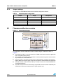
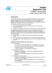
Figure 10. USB Device mass storage demonstration
The connected micro SD Flash is used as storage medium, once connected to a host the
STM32 device should appear in Windows explorer as a removable disk and the user can
have read and write access to it.
Figure 11. USB Device HID demonstration
Once connected to the host, the embedded joystick is used as pointing device
Note:
For device demos a Micro-A to Standard-A plug cable should be used.
Doc ID 15857 Rev 1
25/35
USB OTG FS demonstration description
6.4
UM0721
USB Host mode demonstrations
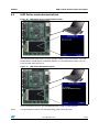
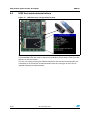
Figure 12. USB Host mass storage demonstration
Once a mass storage device is connected to the board, the application recognizes the
connected USB Flash disk, writes a dummy file and displays all the content of the Flash disk
directory on the LCD screen.
The user can unplug and plug the USB Flash disk only after the dummy file operation has
completed, on the connection and disconnection events the messages on the LCD are
updated to display the detected events.
26/35
Doc ID 15857 Rev 1
UM0721
USB OTG FS demonstration description
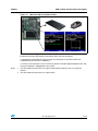
Figure 13. USB Host HID host demonstration
This demonstration supports both mouse and keyboard subclasses. The demo handles
keyboard and mouse HID devices dynamically once they are connected.
If a keyboard is connected the user can type the characters on the LCD screen (the
supported key board layout is QWERTY).
If a mouse is connected, the user can move a pointer inside the displayed pointer area and
the pressed button is highlighted on the screen.
Note:
1
The Host demonstration does not support multi-interface devices such as composite
devices.
2
The Host demonstration does not support hubs.
Doc ID 15857 Rev 1
27/35
USB OTG FS demonstration description
UM0721
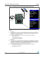
Figure 14. USB Host mass storage with audio support demonstration
Two sets of audio demonstrations built on the USB Host mass storage application are
available:
1.
Wav player
●
This demo plays *.wav files stored in the root directory of the USB Flash disk and can
operate with an external 25 MHz crystal (STM3210C-EVAL board default setting) or
audio quality 14.7456 MHz crystal.
●
This demo supports PCM *.wav audio files with the following configuration:
–
28/35
Data length 8/16 bits
–
Audio frequency: 8 to 96 kHz
–
Channel number: Stereo/Mono
2.
MP3 player
●
This demo plays *.mp3 files stored in the root directory of the USB Flash disk and can
operate with an external 25 MHz crystal (STM3210C-EVAL board default setting) or
audio quality 14.7456 MHz crystal. The MPEG audio decoder libmad is used for MP3
file decoding (supporting only a limited number of file formats).
●
Only *.mp3 audio samples with the following configuration are supported:
–
DataChannel number: Mono
–
Audio frequency: 22 kHz
Doc ID 15857 Rev 1
UM0721
USB OTG FS demonstration description
6.5
USB OTG dual role device demonstration
6.5.1
Hardware configuration
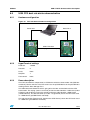
Figure 15. Dual role device hardware configuration
Serial link 1
Serial link 2
USB OTG cable
Micro-A plug
A-Device
6.5.2
6.5.3
Micro-B plug
B-Device
HyperTerminal settings
Baudrate:
115200
Data bits:
8
Parity:
None
Stop bits:
1
Flow control:
None
Demo description
The OTG stack demo is composed of an OTG device which has three modes: Idle (USB bus
turned-off), Device and Host. The OTG stack uses the µC/USB-Device or the µC/USB-Host
working with the Mass Storage Class.
The USB cable ends determine who is going to be the Host and the Device for the OTG
enumeration. The A-plug (series A or mini-A) end of the cable identifies a USB Host (called
A-Device) and the B-plug (series B or mini-B) end of the cable identifies a USB Device
(called B-Device). The left connection (PC Host - Target board) shows the OTG stack used
as a USB Device (µC/USB-Device activated).
The right connection (Target board - Peripheral or OTG Device) shows the OTG stack used
as a USB Host (µC/USB-Host activated).
Doc ID 15857 Rev 1
29/35
USB OTG FS demonstration description
UM0721
When starting the OTG demo, the HyperTerminal displays the activated mode of the OTG
stack and a menu for switching between the modes. Depending on the activated mode, the
menu is:
Idle mode:
1.
Host : switch to Host mode
Device mode:
1.
Idle : switch to Idle mode
2.
Host : switch to Host mode
Host mode:
1.
Idle : switch to Idle mode
2.
Device (Note: First Select HOST Mode In Other Side) : switch to Device mode
3.
File Create : create a file in the mass storage class USB device (MSC).
4.
Show All Files : display the file(s) created in the mass storage class USB device (MSC).
5.
Format If Require : format the mass storage class USB device (MSC).
When the user switches the OTG stack mode the other menu choices change accordingly.
6.5.4
Starting SRP requests
The SRP is used when the Device needs to request the host to activate the VBus.
During the startup of the two boards and after the configuration of the USB cable (mini-A
connector or mini-B connector) the following messages are displayed:
Figure 16. SRP start menu
Board A:
1 - Host mode
Board B:
1 - Host mode
Procedure:
30/35
1.
In Board B, select 1 (Host mode). The message: State-B-SRP-Init is displayed.
2.
In Board A select 1 (Host mode). The A-device moves to A-Host state and the following
menu is displayed in the HyperTerminal window to select the appropriate Host function.
Doc ID 15857 Rev 1
UM0721
USB OTG FS demonstration description
Figure 17. SRP host mode menu
Current Mode: HOST (A_DEVICE)
Select Your Choice:
1. Idle
2. Device (Note: First Select HOST Mode on the other side)
3. File Create
4. Show All Files
5. Format If Require
Enter Your Choice :
6.5.5
Starting HNP requests
The HNP protocol is used to invert OTG roles. To start the HNP process you must select
host mode in the A-device until the following message is displayed:
1.
Idle
2.
Device (Note: First Select HOST Mode on the other side)
3.
File Create
4.
Show All Files
5.
Format If Require
Select Host in the B-Device (choice 2) and then select Device in the A device ( choice 2,
switch to device mode)
The switch will be done and the A-Host becomes an A-device while the B-Device becomes a
B-Host.
Doc ID 15857 Rev 1
31/35
USB OTG FS demonstration package
7
UM0721
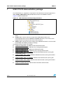
USB OTG FS demonstration package
The OTG FS library is supplied in a single zip file. The extraction of the zip file generates a
folder, STM32_USB-OTG-FS_Lib_V1.0.0, which contains the subfolders shown in
Figure 18 and described below.
Figure 18. USB OTG demonstration package directories
●
Libraries folder: contains the STM32F105xx/STM32F107xx USB OTG FS low-level
driver
●
Project folder: contains the binary image of the USB demonstrations, plus
preconfigured projects for the EWARM and RVMDK toolchains, that can be used to
program the binary images into the internal Flash memory.
●
Utilities folder: contains the binary images of the USB demonstrations, to be used with
the EWARM and RVMDK (provided as backup) .
The following binary images are available:
32/35
●
STM32F10-USBH-HID_OS: USB Host HID host demonstration
●
STM32F10-USBH-MSC_OS: USB Host mass storage demonstration
●
STM32F10-USBF-HID_OS: USB Device HID demonstration
●
STM32F10-USBF-MSC_OS: USB Device mass storage demonstration
●
STM32F10-MSC_MP3_14-7456MHz: USB Host MP3 demonstration (running with
14.7456 MHz crystal)
●
STM32F10-MSC_MP3_25MHz: USB Host MP3 demonstration (running with 25 MHz
crystal)
●
STM32F10-MSC_WAV_14-7456MHz: USB Host Wav demonstration (running with
14.7456 MHz crystal)
●
STM32F10-MSC_WAV_25MHz: USB Host Wav demonstration (running with 25 MHz
crystal)
●
STM32F10-USBO-DRD_OS: USB OTG dual role device demonstration
Doc ID 15857 Rev 1
UM0721
USB OTG FS demonstration package
To program the binary images of the demonstration firmware into the internal Flash memory,
you have to proceed as follows:
●
●
EWARMv5
–
Open the Flash_Loader.eww project.
–
In the workspace toolbar select the project config corresponding to the
demonstration to be loaded. The name of each project config refers to the
demonstration binary image.
–
Load the project image: Project->Download and Debug (CTRL+ D).
–
Restart the evaluation board (Press B1: reset button).
RVMDK
–
Open the Flash_Loader.uv2 project.
–
In the build toolbar select the project config corresponding to the demonstration to
be loaded. The name of each project config refers to the demonstration binary
image.
–
Load the project image: Debug->Start/Stop Debug Session
–
Restart the evaluation board (Press B1: reset button).
Doc ID 15857 Rev 1
33/35
Revision history
8
UM0721
Revision history
Table 6.
34/35
Document revision history
Date
Revision
25-Jun-2009
1
Changes
Initial release.
Doc ID 15857 Rev 1
UM0721
Please Read Carefully:
Information in this document is provided solely in connection with ST products. STMicroelectronics NV and its subsidiaries (“ST”) reserve the
right to make changes, corrections, modifications or improvements, to this document, and the products and services described herein at any
time, without notice.
All ST products are sold pursuant to ST’s terms and conditions of sale.
Purchasers are solely responsible for the choice, selection and use of the ST products and services described herein, and ST assumes no
liability whatsoever relating to the choice, selection or use of the ST products and services described herein.
No license, express or implied, by estoppel or otherwise, to any intellectual property rights is granted under this document. If any part of this
document refers to any third party products or services it shall not be deemed a license grant by ST for the use of such third party products
or services, or any intellectual property contained therein or considered as a warranty covering the use in any manner whatsoever of such
third party products or services or any intellectual property contained therein.
UNLESS OTHERWISE SET FORTH IN ST’S TERMS AND CONDITIONS OF SALE ST DISCLAIMS ANY EXPRESS OR IMPLIED
WARRANTY WITH RESPECT TO THE USE AND/OR SALE OF ST PRODUCTS INCLUDING WITHOUT LIMITATION IMPLIED
WARRANTIES OF MERCHANTABILITY, FITNESS FOR A PARTICULAR PURPOSE (AND THEIR EQUIVALENTS UNDER THE LAWS
OF ANY JURISDICTION), OR INFRINGEMENT OF ANY PATENT, COPYRIGHT OR OTHER INTELLECTUAL PROPERTY RIGHT.
UNLESS EXPRESSLY APPROVED IN WRITING BY AN AUTHORIZED ST REPRESENTATIVE, ST PRODUCTS ARE NOT
RECOMMENDED, AUTHORIZED OR WARRANTED FOR USE IN MILITARY, AIR CRAFT, SPACE, LIFE SAVING, OR LIFE SUSTAINING
APPLICATIONS, NOR IN PRODUCTS OR SYSTEMS WHERE FAILURE OR MALFUNCTION MAY RESULT IN PERSONAL INJURY,
DEATH, OR SEVERE PROPERTY OR ENVIRONMENTAL DAMAGE. ST PRODUCTS WHICH ARE NOT SPECIFIED AS "AUTOMOTIVE
GRADE" MAY ONLY BE USED IN AUTOMOTIVE APPLICATIONS AT USER’S OWN RISK.
Resale of ST products with provisions different from the statements and/or technical features set forth in this document shall immediately void
any warranty granted by ST for the ST product or service described herein and shall not create or extend in any manner whatsoever, any
liability of ST.
ST and the ST logo are trademarks or registered trademarks of ST in various countries.
Information in this document supersedes and replaces all information previously supplied.
The ST logo is a registered trademark of STMicroelectronics. All other names are the property of their respective owners.
© 2009 STMicroelectronics - All rights reserved
STMicroelectronics group of companies
Australia - Belgium - Brazil - Canada - China - Czech Republic - Finland - France - Germany - Hong Kong - India - Israel - Italy - Japan Malaysia - Malta - Morocco - Philippines - Singapore - Spain - Sweden - Switzerland - United Kingdom - United States of America
www.st.com
Doc ID 15857 Rev 1
35/35