1
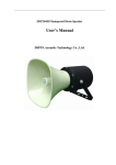
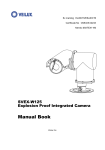
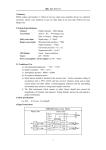
V1421 Series Explosion-proof Camera Housing Installation/Operation Instructions Notice Copyright Statement This manual may not be reproduced in any form or by any means used to create any derivative such as translation, transformation, or adaptation without the prior written permission of Infinova. Infinova reserves the right to change this manual and the specifications without prior notice. The most recent product specifications and user documentation for all Infinova products are available on our web site www.infinova.com Trademarks Infinova® is a trademark of Infinova. Copyright © 1993-2014 Infinova. All rights reserved. Contents subject to change without prior notice. Infinova and its logo are registered trademarks of Infinova. All other trademarks that may appear belong to their respective proprietors. FCC Warning V1421 Series Indoor/outdoor Explosion-proof Housing complies with Part 15 of the FCC rules. Operation is subject to the following two conditions: This device will not cause harmful interference. This device must accept any interference received, including interference that may cause undesired operations. The V1421 has been tested and found to comply with the limits for a Class A digital device, pursuant to Part 15 of the FCC rules. These limits are designed to provide reasonable protection against harmful interference when the equipment is operated in a residential environment. This equipment generates, uses and can radiate radio frequency energy and if not installed and used in accordance with the instructions, may cause harmful interference to radio communications. There is no guarantee that interference will not occur in a particular installation. Read this manual carefully before installation. This manual should be saved for future use. Important Safety Instructions and Warnings Electronic devices must be kept away from water, fire or high magnetic radiation. Clean with a dry cloth. Provide adequate ventilation. Unplug the power supply when the device is not to be used for an extended period of time. Only use components and parts recommended by manufacturer. Position power source and related wires to assure to be kept away from ground and access way. Refer to qualified personnel for all service matters. Save product packaging to ensure availability of proper shipping containers for future transportation. Indicates that the un-insulated components within the product may carry a voltage harmful to humans. Indicates operations that should be conducted in strict compliance with instructions and guidelines contained in this manual. Table of Contents Chapter I Product Description...................................................................................1 Chapter II Product Model ............................................................................................2 Chapter III Features......................................................................................................3 Chapter IV Explosion Proof Outline.........................................................................4 Chapter V Specifications ............................................................................................5 Chapter VI Product Dimension and Installation Demonstration ...........................6 6.1 Housing Dimension (Unit: mm) ..........................................................................6 6.2 Housing base mount holes position .....................................................................6 6.3 Bracket Mount Dimension (Unit: mm)................................................................7 6.4 Camera Mounting and Connection inside Housing .............................................7 6.5 Installation Process and Demonstration...............................................................9 6.6 Wiper Control ....................................................................................................10 Appendix Instructions for Pigtail............................................................................... 11 Chapter I Product Description Explosion-proof housing is used worldwide for those environments containing dangerous explosive gases. Its design perfectly meets the requirements in terms of installation in dangerous area, explosion proof and dust proof. The V1421 Explosion-proof housing is explosion-proof housing that meet stringent explosion-proof requirements. Its shell and mainly body are 316 stainless steel construction that has fine airproof and erode-proof capability for both indoor and outdoor installation. Fixed Camera, Zoom camera can be installed in housing. It’s applied for environmental conditions including chemical industry, oil storeroom, and fuel dock and magazine etc applications. The features in the design are in accordance with IECEx standard. The explosion-proof class is ExdIICT6. Environmental protection is: IP66, which means it can perfectly prevent dust from getting in and free from water clean. 1 Chapter II Product Model V1421-15SHB6-2 Camera housing, explosion-proof, 15 inch, w/ sunshield, wiper, heater, blower, 316 Stainless Steel, outdoor, 24VAC V1421-15SHB7-2 Camera housing, explosion-proof, 15 inch, w/ sunshield, wiper, heater, blower, 316 Stainless Steel, outdoor, 110VAC V1421-15SHB8-2 Camera housing, explosion-proof, 15 inch, w/ sunshield, wiper, heater, blower, 316 Stainless Steel, outdoor, 240VAC V1421-15A6-2 Camera housing, explosion-proof, 15 inch, 316 Stainless Steel, indoor, 24VAC V1421-15A7-2 Camera housing, explosion-proof, 15 inch, 316 Stainless Steel, indoor, 110VAC V1421-15A8-2 Camera housing, explosion-proof, 15 inch, 316 Stainless Steel, indoor, 240VAC Mounts V1665-W1 Adjustable Wall Mount, 316 Stainless Steel Housing model is presented as V1421-XXXX, of which “V” stands for Infinova. 1421 represents the explosion proof series products from V1400-V1499 and 1421 belongs to explosion proof series products. The detailed definition is shown as follows: V1 4 2 1 2 316 6 24VAC 7 110VAC 8 240VAC B With Blower No letter Without Blower 12" Housing 12 H 15" Housing 15 18 " Housing 18 22" Housing 22 2 With Heater No letter Without Heater S With Sun Shroud A Without Sun Shroud Chapter III Features For explosive gas atmospheres part 2: suited for the dangerous sites with explosive air mixture division 1 and division 2, flammable gas, steam classification Ⅱ A, B, C, and temperature classification T1-T6 Toughened glass used for explosion-proof housing front window and stainless steel used for body and base. Environmental protection: IP66 Explosion proof level: ExdⅡCT6 Cable leading port conformed to GB3836.1-2010 and GB3836.2-2010 national standard Most cameras and lens available inside Applicable to fixed bracket or adjustable wall mount bracket V1665-W1. 3 Chapter IV Explosion Proof Outline When the explosive gas mixture blows up inside pan/tilt, the explosion-proof housing should not be damaged and the explosive flame inside will not cause other surrounding explosive mixtures to blow up via explosion-proof joint surface. In the process of pan/tilt structure design, we have fully taken housing strength, structure, temperature and other respects into consideration to make it would not spark under normal application to ensure the security and reliability of product. Thus: The components used in pan/tilt housing have been through static pressure and water pressure test 1.5MPa, according to GB3836.2/IEC60079-1, for 10-60s, and it will be qualified when no water is leaking. Housing is explosion-proof structure, and its explosion-proof joint surface conforms to the The bolts of explosion-proof housing should be fixed with spring gaskets, to protect against getting regulation of GB3836.2/IEC60079-1. loose. The housing cover, housing upper cover, housing rear cover, body cover, body cover accessories, body upper cover, base shaft base are all the explosion-proof components that comply with the regulation. Under normal working condition, the cover temperature of pan/tilt can not exceed +80℃. The cable leading device for housing employs the rubber sealing ring pressed against nut. The cable is permanent, reserved at least 1m. 4 Housing has been grounded internal and external. Chapter V Specifications V1421 General Electrical Electrical Parameter: 24VAC, 60/50Hz, <1A; 110VAC/240VAC, 60/50Hz, <250mA Power Consumption: 30W (maximum) Mechanical Construction: 316 Stainless Steel Environmental Rating: IP66 Window Glass: Diameter 67mm toughened glass Cable Connection: 1 cable port, connected to housing rear cover; cable diameter 10mm. External Dimensions: (W x H x L): Internal Dimensions (W x H x L): 6.46" x 6.46" x 18.50" (164 mm x 164 mm x 470 mm) 2.68" x 3.15" x 10.24" (68 mm x 80 mm x 260 mm) Weight: 30.86 lbs. (14 kg) Shipping weight: 33.07 lbs. (15 kg) Box Dimensions (W x H x L): 9.53" x 9.92" x 21.73" (242mm x 252mm x 552mm) Environmental Environmental Air Pressure: 86kpa~106kpa Temperature: -4 ºF ~ 140 ºF (-20 ºC~+60 ºC) Humidity: 95% RH (+25ºC) Application: For dangerous sites with explosive air mixture division 1 and division 2, flammable gas, steam classification II A, B, C, and temperature classification T1-T6 Compliance IECEx, ExdIICT6, Certificate No.: IECEx CQM 09.0001 CNEx, ExdIICT6, Certificate No.: CNEx08.1401X V1665-W1 General Construction: 316 Stainless Steel Weight: 8.82 lbs. (4kg) Shipping weight: 11.02 lbs. (5kg) Box Dimensions (L x W x H): 17.52" x 12.60" x 6.69" (445mm x 320mm x 170mm) 5 Chapter VI Product Dimension and Installation Demonstration 6.1 Housing Dimension (Unit: mm) Figure 6-1 Side View Figure 6-2 Front View Figure 6-3 Rear View 6.2 Housing base mount holes position Figure 6-4 6 Figure 6-5 6.3 Bracket Mount Dimension (Unit: mm) Figure 6-6 Figure 6-7 6.4 Camera Mounting and Cable Connection inside Housing Please follow the steps below to mount the camera and connect the cables. Note: during this process, please do not connect the external power supply. 1. Removal of back cover To remove the back cover, first unscrew the six screws on the back cover and pull out the 8pin terminal block (see Figure below); Figure 6-8 2. Removal of front cover Be very careful for the housing with wiper during removal of front cover. You need to remove the screw and spring behind the wiper shaft during removal of back cover. Meanwhile, you need to pull out the 2pin terminal block on the front cover and middle PCB before removal of front cover. 7 Figure 6-9 3. Removal of camera mounting plate and cable connection Remove the four screws on the camera mounting plate so that you can remove the camera mounting plate from the housing; then, connect the inside cables (with labels) to the relevant power port, RS485 port and video output port on the camera and, finally, fix the camera to the mounting plate (for lens mounting, please refer to the user manual for lens). Notice: the red and black cable should be connected to the power port (24VAC power supply for camera), the blue and brown cable should be connected to the RS485 port (brown + blue -) and the BNC connector should be connected to the BNC port. RS485 Port Video Output Port Power Port Figure 6-10 4. Fixing camera mounting plate Install the camera mounting plate to the housing and fasten the four screws. 5. Installation of front cover (reverse with step 2): first connect the 2pin terminal block. Be careful to install the screws and spring behind the wiper shaft. 6 Installation of back cover (reverse with step 1): first connect the 8pin terminal block. During the process, make sure the pigtail inside the housing may not interfere with the wiper structure. Then, the camera installation and cable connection are completely finished. 8 6.5 Installation Process and Demonstration 1. Firstly fix wall mount bracket to the desired wall via four installation holes. Then secure the screws in the upper and lower adapter. Figure 6-11 2. Fix housing onto the bracket upper adapter by installation holes drilled on base. Then pack up cables. First, arrange cable along the housing and pull out cable through the cable hole on housing base, then through the hole between lower adapter and wall mount bracket, and lead out cable from the hole on the wall or lower part of wall mount bracket (make sure cable connection is smooth and flexible). If leading out cable from lower part of wall mount bracket, please pay attention to fixing cable fastener. Refer to Figure 6-9 (take cable from lower part of wall mount bracket as an example). 9 Figure 6-12 3. After that, adjust the screws fixed between upper and lower adapter and the screws between lower adapter and wall mount bracket to provide a good angle of view of camera within the housing. Then fasten those screws steadily (in the process of adjustment, please be careful when pulling the cables around). 6.6 Wiper Control If the housing with wiper are provided, user can extend the two wiper control cables to desirable length and connect them to the attached wiper switch. Turn on the switch to start wiper, and turn off the switch to stop wiper. Note: please take explosion-proof measures when installing wiper. The wiper can be remotely controlled with the help of Fiber Optics. In that case, the wiper control cables should be connected to the contact closure port of Fiber Optics. 10 Appendix Instructions for Pigtails Please follow the mark on the pigtail for cable connection after the housing is properly mounted. Please see the table below for the definition of pigtail terminal: Mark Cable Color BNC Definition Video output RX+ Brown RX- Blue ~ Red ~ Black EARTH Yellow-Green + Green - Grey RS485 Power input (AC) Earth Wiper switch Notice: 1. For model without wiper, the wiper switch cable is not included. 2. Please pay attention to the power voltage, power frequency and current on the label during power cord connection so as to avoid any damage caused by wrong connection. 11 Infinova 51 Stouts Lane, Monmouth Junction, NJ 08852, U.S.A. Tel: 1-888-685-2002 (USA only) 1-732-355-9100 Fax: 1-732-355-9101 [email protected] V1.4 1406