1
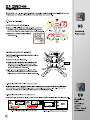
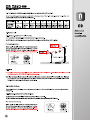
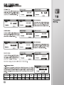
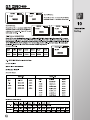
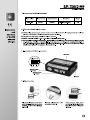
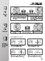
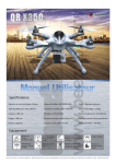
walkera
(PRO)
solution
Latest
photography
control
Control
High capacity battery makes long
o Equipped with Brushless Gimble
1:r
—LF
_FL
Specifications:
Main Rotor Diameter: 582mm
Brushless Motor spec: WK-WS-28-008C
Main Rotor Blade Length: 232mm
Brushless ESC spec : WST-15A(G/R)
Takeoff Weight:<1350g
Length: 289mm
Receiver: DEVO-RX703
Experience Level: Intermediate
Width: 289mm
Transmitter(option): DEVO-F7/10/7/85/12S
Recommended Environment: indoor/Outdoor
Height:205mm
Battery(option): 11.1V 5200mAh Up°
Completion Level: RTF/BNF
Weight: 986g (Battery included)
Features:
- • .
-2j/
DEVO-M
Ls a Multi-Axis control platlo,n designed
for rorophotograhpy hobbwest
GP5 Altitude hold system
—AFL—
113
Professional DEVO 10 channel
(option)
n
Professional DEVO F7
5.8G FPV transmitter
(option)
a
(iD
El
One Key Go Home
5.8G goggle for longer FPV
transmission (option)
High capacity battery makes
long flight time
Intelligent Flight Mode
Or)
2.4G !WS
2.46 WiFi HD transmission
image(option)
LLIil HI
inft
0
Equipped with professional gimble
Support Look I Gopro Hero3 1 Sony(11DR-AS30V)
Failsafe to return & Landing
Low voltage protection
Contents
1. Forewords
1
2. Safety matters needing attention
1
2.1 Important Statement
1
2.2 Safety matters needing attention
08. Basic Flight Instruction
6
8.1 Main Control System Control Mode
6
8.2 Code binding
6
8.3 Motor unlock/lock/ Stop rotating
6
1
8.4 Compass Calibration
7
(1) Far away from obstacles and people
1
09. Advanced function specification
8
(2) Keep away from humidity
1
9.1 The flowchart of GPS Satellites Signal
(Need to connect with GPS module)
8
(3) Proper operation and maintenance
1
9.2 Position Hold
8
(4) Avoid flying alone
1
9.3 One Key Go Home
8
(5) Safety operation
2
9.4 Failsafe to Return & Landing
9
(6) Away from highly spinning parts
2
9.5 Low Voltage Protection
10
(7) Protect from heat
2
9.6 Intelligent Orientation Control(IOC) Flight
10
2.3 Attention before flight
2
10. Transmitter Setting
11
10.1 DEVO-10(optional radio) setting
11
10.2 DEVO-F7(optional radio) setting
13
10.3 DEVO-7(optional radio) setting
15
3. Definition of Aircraft Orientation
3
4. Equipments
3
10.4 DEVO-8S/12S(optional radio) setting
16
4
11. Instruction and attention
of GA005 balance charger
17
5. Assembly Instruction
5.1 Propellers Installation
4
11.1 Parameters of GA005 balance charger
17
5.2 Compass & Landing Gear Installation
4
11.2 Features of GA005 balance charger
17
11.3 Instruction of GA005 balance charger
17
11.4 Operation steps
17
11.5 Charging status corresponding to LED
18
6.1 Brushless ESC and Brushless motor Connection ---- 4
11.6 Matters needing attention
18
6.2 Brushless ESC and Power board Connection
4
11.7 Maintenance of battery pack
18
7. Main control board guideline
5
12. Steps of flight
19
7.1 Main controller: DEVO-M
5
13. Flight over
19
7.2 Main control board(DEVO-M) and
Brushless ESC Connection Illustration
5
Appendix 1 - Manual flight control
19
7.3 Receiver: RX703
5
7.4 Main Control Board Installation Requirements
5
Appendix 2 - Trimming the Manual flight actions
20
6.
Brushless ESC/Brushless
motor/Power board connection
4
GPS altitude hold system
Dear customer:
Thank you for purchasing a Walkera radio control aircraft product. In order to quickly and safely master the
operation of the "QR X350PRO", please read the user handbook carefully and then keep it in a safe place for
future consultation and reference.
01
Forewords
2.1 Important Statement
(1) This product is not a toy. It is a piece of complicated equipment which harmoniously integrates engineering
materials, mechanics, electronics, aerodynamic and high frequency radio. Correct installation and adjustment
are necessary to avoid accidents taking place. The owner must always operate in a safe manner. Improper
operation may result in serious property damage, bodily injury or even death.
(2) We accept no liability for damage and consequent damage arising from the use of these products, as we have
no control over the way they are maintained, used and operated.
(3) This product is suitable for experienced Aircraft pilots aged 14 years or more.All minors must be accompanied
by a responsible adult when flying.
(4) The flight field should be legally approved by the local govemment. We accept no liability for any safety duties
or fines arising from operation, usage or mis-control after the sale of the products .
(5) We consign our distributors to offer technical support and service after sale. Please contact the local distributors
for problem resolution caused by usage, operation, maintenance, etc.
2.2 Safety matters needing attention
0
Safety
matters
needing
attention
Aircraft flight is a high risk hobby, whose flight should be kept far away from other people. Mis-assembled or
broken main frame, defective electronic equipment, and/or problematic radio system will lead to unforeseen
accidents such as bodily injury or property damage. The pilot MUST pay attention to the flight safety and
UNDERSTAND his responsibility for accidents caused by his carelessness.
(1) Far away from obstacles and people
c4°
An Aircraft in flight has risk of uncertain flight speed and direction which is
potentially dangerous. When flying, please keep your Aircraft far away from
people, high buildings, high-tension lines, etc, and avoid operating in rain,
storms, thunder and lightening.
(2) Keep away from humidity
Aircraft should be kept away from humidity and vapor because its complex,
precise electronic components and mechanical parts may be damaged.
(3) Proper operation and maintenance
Please use Walkera original spare parts to upgrade, modify or maintain your
Aircraft in order to ensure its safety. Please operate your Aircraft within the
range of functions permitted. It is forbidden to use it outside of the safety laws
or regulations.
(4) Avoid flying alone
At the beginning of leaming about radio-controlled flight there are some difficulties
to overcome. Please avoid flying alone. Invite experienced pilots to guide you
(two of the most effective methods to practice are via a PC flight simulator and/or
under the supervision of a skilled pilot).
1
as:(1;121
GPS altitude hold system
(5) Safe operation
Please fly your Aircraft according to your physical status and flight
skills. Fatigue, listlessness and mis-operation will increase the
possibilities of accidental hazard.
A
•
I
02
(6) Away from highly spinning parts
Please keep pilot, people and object away from the spinning blades
of both main rotor and tail rotor.
(7) Protect from heat
An Aircraft is made from metal, fiber, plastic and electronic components,
etc. Please keep away from heat and sunshine in order to avoid
distortion, even damage, caused by high temperatures.
2.3 Attention before flight
(1) Ensure the battery packs of both transmitter and receiver are fully charged (saturated).
(2) Ensure both the throttle stick and the throttle trim of your transmitter stay at the lowest positions before
operation.
(3) Please strictly obey the order of turn-on and turn-off before operation. When starting your flight, please turn
on your transmitter first, and connect the power cable of your helicopter last.
When finishing your flight, please disconnect the power cable of your helicopter first, and turn off your transmitter
last. An upset in the order of connection may cause your helicopter to loose control. Please cultivate a correct
habit of turn-on and turn-off.
(4) Assure there are solid connections between the power cables of battery pack and motors. Continuous vibrations
in flight may loosen the battery tie-ins.
2
Safety
matters
needing
attention
GPS altitude hold system
We define the orientation of Aircraft in order not to cause confusion in the following descriptions. That is to say,
the tail boom of Aircraft is facing the pilot (tail in), and its head facing forward (front of pilot). The left hand of
pilot is the left side of Aircraft, the right hand of pilot is the right side of Aircraft Its head is to the front and its tail
boom is to the back. The direction in which main body of Aircraft is facing is up, and its skids are facing down.
up
A
right
03
Allli
*
E1
11 .1
1 04%,-ILAMIN.,..- -...I
a
111110a
Vt'a iltillilr eim....
-,
j ". ,.., :,.w 1,
Mi
l WAILiiiiiik
lig.NIL%
mr•••!.2-
Definition
of Aircraft
,
11/fr rifferf
front
back
Orientation
14
left
down
*I ••• la
ail - 110.
04
A QR X350PRO
A Transmitter (Option)
111
Equipments
A Li-polymer battery pack(Option)
A !LOOK Camera(Option)
A Charger(Option)
A Main rotor blades
U•ar Handbook
A User Handbook
A Tool kit
3
QR X350PRO is an all-in-one new model, which is specialized design for Walkera fans. All testing has been
finished before out of factory, only simply set up is needed before your ready to fly.
5.1 Propellers Installation
05
Assembly
Instruction
5.2 Compass & Landing Gear Installation
6.1 Brushless ESC and Brushless motor Connection
6.2 Brushless ESC and Power board Connection
Yellow
Green
Yellow
Red
Green Ni) Rezd
hod
Brushless ESC and Brush ess
motor (M1/M3)connection
Brushless ESC and Brushless
motor (M2/M4)connection
6.1 Brushless ESC and Brushless motor Connection
4
6.2 Brushless ESC and Power board Connection
GPS altitude hold system
7.1 Main controller: DEVO-M
AUX3: Spare port
Compass: To link Compass
AUX2: To IOC
USB: Upgrade channel
07
Main control
board guideline
AUX1: Spare port
GEAR: To control Mode Switch
AuxaN.
Ml: Connect with first
way brushless ESC
RUDD: To control Rudder
ALIN211.
DEVO-M
.11144
M3: Connect with third
way brushless ESC
AL. I
GEAR'
cleUenlion
1541
M2
M2: Connect with second
way brushless ESC
Main controller
MADE IN CHINA
M4: Connect with forth
way brushless ESC
THRO: To control Throttle
THRO
ELEV: To control Elevator
(forward & backward)
EL,
AILS ►
CHECK Powell *DATA BUS
JUMP PORT iT
AILE: To control Aileron
(leftward & rightward)
CHECK POWER: To check voltage
(Connect with power board)
DATA BUS: Data transmission
(connect DEVO-RX703)
JUMP PORT.: Jumper port, when
regular receiver is need, insert
random equipped bind plug pls.
GPS: To link GPS module
LED: To link LED
7.2 Main control board(DEVO-M) and Brushless ESC Connection Illustration
The first way brushless ESC
M1 Port
The second way brushless ESC
M2 Port
The third way brushless ESC
M3 Port
The forth way brushless ESC
M4 Port
DEVO-M
Main controller
7.3 Receiver :RX703
DATA BUS: data transmission(connect with DEVO-M)
4..7.
•.•11
-1
1
171
OATA BI ,F ig
AUX 4 I'M
cleUenti
on
AUX
Een%fez
AUX
RX•r7 03
E
MADE in
AUX5: Auxiliary 5 to connect G-2D controller ( ROLL port)
1.
I.
2z
.46H
C
AUX4: Auxiliary 4 to connect G-2D controller ( PIT port)
cw. CLEAN I.
1
AUX3: Auxiliary 3
CLEAN: Clear fix ID code. Please insert the bind plug to clear
the fix ID, connect a 5V power into other output terminal, the red
indicator will flash slowly means fix ID has been cancelled,then
put out the bind plug.
EErmrxm
Single wire ROLL port
CE
Single wire PIT port
7.4 Main Control Board Installation Requirements
(1) Label side towards the top of the aircraft.
(2) Side with ESC connector towards forward of the aircraft.
(3) Keep horizontal with the body of the aircraft.
(4) Please install the main control board at the CG positon and keep all ports are free to connect.
5
GPS altitude hold system
8.1 Main Control System Control Mode
8.1.1 Control Mode Classification
There are three control modes according to the 3-position switch: Manual Mode \Position Hold Mode \ One Key
Go Home.
8.1.2 Control Mode Switch Setting(The factory setting is RTF, the default setting use "MIX" switch. please refer
"Transmitter device output" for method).
08
Please choose a 3-position switch as control mode switch before flight.
(1) Manual Mode
(2) Position Hold Mode
MIX Switch to"0"PosItIon
MIX Switch to"1"PosItIon
(3) One Key Go Home
MIX Switch to"2"PosItIon
8.2 Code binding
Please follow the rule "Turn on transmitter first
and aircraft battery later" Turn on the radio first,
please connect the aircraft power in 10 second
later. The Code binding successfully when the
left green LED indicator flash quickly to slowly
and then light out last.
8.3 Motor unlock/lock/ Stop rotating
8.3.1 Motor unlock
Once binding, push the throttle stick to the lowest position and keep the throttle trim at the neutral position. Then
push the rudder stick to the far left side and the Left green LED indicator turn solid Green, that means motors
are unlocking. If you push the throttle up, the motors will rotate.(Note, the motors can unlock only under manual
mode)
Model (Throttle stick on the right)
Mode2(Throttle stick on the left)
At
iii,
--.) -----)
/m
1.1"
0
111)
.---i id
‘---Rudder stick
%‘1. 1
_
--------„
.il )
7•
Model (Throttle stick on the right) Mode2(Throttle stick on the left)
I mr,•(
,
-I AryG,
ELEV stick
Throttle stick Throttle \ Rudder stick
7--i4111
.d-. --1
.- I'
\ie,
••11
s(
1
Rudder stick Throttle stick
8.3.1 Motor unlock
------,
ELEV stick
Throttle\Rudder stick
8.3.2 Motor lock
8.3.2 Motor lock
Down the throttle stick to the lowest position, move the rudder stick to far right, the motors are locked when the
left green LED indicator light out. If you push the throttle up, the motors won't rotate.
Notes: The aircraft is in Motor lock status after Code binding successfully.
8.3.3 Motors stop rotating
If you push the throttle to the lowest positon, the motors stop rotation.
8.3.4 Notes
(1) After unlock, the motors would get into lock status after 10 seconds.
(2) The factory default setting for the motors are locked after finished ID binding.
6
Basic Flight
Instruction
GPS altitude hold system
8.4 Compass Calibration
After successful calibration for QR X350PRO, it's just plug and play to use.
The following condition need to calibrate the compass:
(1) The first time for flight, it takes longer time to inspect the GPS signal.
(2) When you are in a new environment.
08*
Basic Flight
Instruction
8.4.1 Compass Calibration
Please inspect the motors lock or not before calibration. The factory default setting for the motors are
locked after finished ID binding. If the aircraft need to re-calibration after flight, it is a must to lock the
motors again before calibration.
(1) Put aircraft to the horizontal position to lock the motors ( lock method refer to 8.3.2).
(2) MODE 1: keep the throttle stick at the lowest left corner
and push the elevator and rudder stick to the lower right
corner, compass calibration mode entered.
Mode 2: Keep the throttle/rudder sticker to the lowest
position and move to the right side, then push the Elevator
stick to the lower left corner, compass calibration mode
entered.
Model (Throttle
stick on the right)
Mode2(Throttle
stick on the left)
ThrottlelRudder stick ELEV stick
EIEVIlludder stick Throttle stick
(3) Rotate the QR X350PRO 360 degree according to forward/backward, left/right and horizontal level orientation(please
follow the figures) and leave it on the horizontal place for 30 seconds, the left green LED flash quickly till
light out which means calibration finished.
Up
1,-,---
•• laaar ,
- AL
, -k--"1101.0 •
•
1
,-.
---.4-11111
A
--,,,...•_•—•
•,_
Ll ,
rAi".. - -
6m...
--ii6
_ ,— i"
'
liA%
-
Left
1 Up
Up
Right
_
Left
•
Down
Forward & backward 360 degrees rotation
=
Right
•
-1
i
R ght
•
I Down
Down
Leftward & rightward 360 degrees rotation
e , .S.
---
Left
•
'
/ma
Horizon level 360 degrees rotation
(4) Please reconnect the aircraft power after calibration.
8.4.2 Notes:
(1) Please keep away from magnetic matrials area to calibration.
(2) Please recalibrate the compass when the vehicle is circled and drifted during the flying.
(3) Please recalibrate the compass if it is replaced or the vehicle position is changed.
(4) Please check whether there is a strong magnetic field nearby disturbing the compass if the calibration is
failed constantly.
(5) Please reconnect the power of the aircraft and recalibrate the Compass if crash.
7
(pmc)
_FL
GPS attitude hold system
9.1 The flowchart of GPS Satellites Signal(Need to connect with GPS module)
Notes:The starting position means a point before the departure of the flight control system initialization and
automatically check the complete aircraft location.
<5
GPS Satellites
The right
Green LED
status
No
blinking
5
Blinking
once
6
7
9
8
11
10
12
Blinking Blinking Blinking Blinking Blinking Blinking Blinking
twice
3 times 4 times 5 times 6 times 7 times 8 times
Advanced
function
specification
9.2 Position Hold
9.2.1 Here pre-conditions for Hold Position:
(1) The Aircraft is in normal flight statusand battery voltage is normal.
(2) GPS function and signal is in good conditionp5 satellites, the right Green LED blinking)
Position Hold Setup:
When toggle the MIX switch to "1"position(don't move
other sticks) during flight under manual mode, it means
the QR X350PRO entered Position hold mode. Please
keep the throttle stick at neutral position under this mode.
Hover point 2
(E2, N2, h2)
Hover point 1
(El, Ni. hi)
S
h2
hi Position Hold hover
•
Ground
9.2.2 Note
(1) The flight status can be controlled by radio under GPS position hold mode. Throttle stick should be neutral
first if you want the QR X350PRO hold at other points.
(2) Please use manual mode to start to fly, switch to hold position mode the aircraft will hover stable, after landing to
the ground and push the throttle stick to the lowest position, the motor can lock automatically,and later need
to re-switch to manual mode the motor can unlock.
9.3 One Key Go Home
Starting position is the place where the main control board finishes initialization and auto check before
taking off.
9.3.1 Here pre-conditions for One Key Go-Home:
(1) The Aircraft is in normal flight status and battery voltage is normal.
(2) GPS function and signal is in good condition (?-5 satellites, the right Green LED blinking).
One Key Go Home Setup:
When toggle the MIX switch to "2"position(don't move
other sticks) during flight under manual mode, it means
the QR X350PRO entered One Key Go Home. Please
keep the throttle stick at neutral position under this mode.
8
09
0
MIX Switch
to"2"Position
Throttle stick
return neutral
GPS altitude hold system
9.3.2 The flowchart of One Key Go-Home
-.
A.
Record return position
Hover
S
s
Rutum position
.
MIX Switch
to"2"Position
.
s
6±t
Ground
•
Aircraft
0
o
II
Actual Go back
landing range(Relate
b'the GPS sign°
Ready for
go back
Advanced
.
_
First Hover then Landing
V
,, '•,.
_
ach
:
1 221
"Zar
: ,
K.
Appr
al.
Keep MIX Switch
to°2"Position
function
..... _..)
Record return position
specification
all
9.3.3 Notes
(1) Please use manual mode to start to fly, switch to one key go home mode the aircraft begin to return home,
after landing to the ground and push the throttle stick to the lowest position,the motors would lock automatically,and
later need to re-switch to manual mode the motors can unlock.
(2) To make sure the safe useage,please make sure to record the starting position before departure and know
exactly where the starting position is.
(3) When return home the aircraft straight flight along the line on the horizon which between the start position
and the failsafe point.
(4) The aircraft may be stuck if there are big obstacles around or windy conditions.
(5) When GPS signal is bad or GPS is unable to work, the failsafe will not work and the aircraft will not return.
9.4 Failsafe to Return & Landing
It is a protective measure that prevents aircraft from missing signal and out of controlling. When aircraft
lose control signal, it can enter Failsafe go home automatically.
9.4.1 The flowchart of Failsafe to Return and Landing
Hover
Record return position
Signal failure
A
Ruturn position
Ground
0
0
Aircraft
Actual Go back
landing range(Relate
to the GPS signal)
Signal failure
MC)
First Hover then Landing
Record return position
Ready for
go back
A
•
•
9.4.2 Notes
(1) To make sure the safe useage,please make sure to record the starting position before departure and know
exactly where the starting position is.
(2) When return home the aircraft straight flight along the line on the horizon which between the start position
and the failsafe point.
(3)The aircraft may be stuck if there are big obstacles around or windy conditions.
(4)When GPS signal is bad or GPS is unable to work, the failsafe will not work and the aircraft will not return.
9
_FL
GPS altitude hold system
9.5 Low Voltage Protection
Low Voltage Protection is a design to avoid the aircraft to crash by the low voltage of the battery.
When the battery voltage is too low, the left green LED will slow blink warning, the aircraft will descent slowly.
Attention: The voltage alarm will be reminding when the aircraft at fixed point and fixed height or one key return
mode, please switch to manual mode to control as soon as possible.
09
9.6 Intelligent Orientation Control (IOC) Flight
9.6.1 Make sure before use IOC function
(1) Aircraft is in normal condition and battery is full charged.
(2) Please make sure you know the basic flight and then use this function. You can make it fly back smoothly by
ELEV Stick after activate the function.
9.6.2 IOC Definition
In the IOC mode, the quadcopter's forward direction moves by ELEV/AILE stick of the transmitter and only be
relatived by the original RX binding positon. Because the RX reset position determinated the quadcopter's flight
direction in IOC mode. And the flight direction be no relative with the head direction or the radio control direction.
Note:
(1) In Manual mode, the quadcopter's flight direction is same as its head direction.
(2) In IOC mode, the quadcopter's flight direction is same as the RX reset position.
9.6.3 IOC Setup
Turn the FMOD switch to Position "2", the quadcopter enter into IOC mode, in IOC mode, the quadcopter can
move by the ELEV/AILE stick of the transmitter (if RTF, the default switch is FMOD and it is close. For setting,
please ref to radio setting).
Note:
(1) The quadcopter is in manual mode when FMOD switch turns to postion "0" and "1";
(2) The quadcopter is in IOC mode when FMOD switch turns to postion "2".
Model (Throttle
stick on the right)
Mode2(Throttle
stick on the left)
Usually
J.
MOO
ELEV Stick
AILE Stick
Graphic description:
ELEV/AILE Stick
forward direction z> nose direction
9.6.4 Attention
(1) Please don't make flight after you activate IOC.
(2) Please close IOC when you do normal flight.
10
In course lock
(IP
FMOD Switch to
"0" or "1" Position
FMOD Switch
to "2" Position
Advanced
function
specification
GPs altitude hold system
10.1 DEVO-10(optional radio)sefting
10.1.1 Boot Screen
Elevator trim
Throttle trim
Transmission power display
Battery capacity
display
I II
cleention
Transmitter
Setting
Timer display
Throttle percentage
value
Model name
MOD 1
00:00
Model type
display
.0%
Rudder trim display
Aileron trim
display
10.1.2 Type Select
Press ENT to get Main Menu and press UP or DN to select Model Menu, press ENT to enter Model Menu; Press
UP or DN to select Type Select and press ENT to enter Type Select setting interface. Press R or L to get the
icon of Airplane and press ENT to confirm, then press EXT to return to Model Menu.
10.1.3 Model Select
Press UP or DN to select Model select in Model Menu, press ENT to enter Model Select setting interface; Press
UP or DN to select MOD 1, press ENT to confirm and then press EXT to return to Model Menu.
10.1.4 Model Name
Press UP or DN to select Model Name in Model Menu, press ENT to enter Model Name setting interface; Press
UP or DN to select the character and figure which need to be changed, press R or L button to change the character
and figure, named model as X350PRO. Press ENT to confirm and then press EXT to return to Model Menu.
.®
Model Select
Model Name
1
No. 1
2 ,-
MOD 2
Name
3 ‘‘-
MOD 3
1111
X350PRO
4 ‘‘- -AlOD 4
10.1.2 Type Select
10.1.4 Model Name
10.1.3 Model Select
Wing Type
10.1.5 Wing Type
Press UP or DN to select Wing Type in Model Menu, press ENT to enter
the Wing Type setting interface; Press UP or DN to select "Wing Type"
setting, press R or L to select "Normal", then press ENT to confirm and
then press EXT to exit.
Wing Type
Normal
V-Tail
Inhibit
10.1.6 Device Output
Press UP or DN to select Device Output in Model Menu, press ENT to enter the Device Output setting interface.
(1) Gear setting
Press UP or DN to select "Gear" setting,
press R or L to select "MIX SW"; Press
UP or DN to select "Function" setting,
press R or L to select "Active".
Device Output
Device Output
Gear
Gear
MIX SW
MIX SW
Function
Function
Active
Active
11
e-Th
n
GPs altitude hold system
(2) Flap setting
Device Output
Press UP or DN to select "Function" setting
below Flap, press R or L to select "Active";
Press UP or DN to select "Flap" setting,
press R or L to select "GEAR S'.
Device Output
.11111
.11111
Flap
Flap
•
GEAR SW
GEAR SW
Function
Function
Active
Active
•
Device Output
Device Output
AEI
(3) AUX2 setting
AUX2
AUX2
Press UP or DN to select "AUX2" setting,
press R or L to select "FMOD SW";
Press UP or DN to select "Function"
setting, press R or L to select "Active".
FMOD SW
FMOD SW
Function
Function
Active
Active
•
•
(4) AUX3 setting
10
Device Output
Device Output
AUX3
AUX3
Press UP or DN to select "AUX3" setting,
press R or L to select "RUDD D/R"; Press
UP or DN to select "Function" setting,
press R or L to select "Active".
RUDD D/R
RUDD D/R
Function
Function
Active
Active
•
•
Device Output
Device Output
.11111
AUX4
AUX4
Press UP or DN to select "AUX4" setting,
press R or L to select "AUX4 KB"; Press
UP or DN to select "Function" setting,
press R or L to select "Active".
AUX4 KB
AUX4 KB
Function
Function
Active
Active
(5) AUX4 setting
•
(6) AUX5 setting
Device Output
Device Output
Press UP or DN to select "AUX5" setting,
press R or L to select "AUX5 KB"; Press
UP or DN to select "Function" setting,
press R or L to select "Active".
AUX5
AUX5
AUX5 KB
AUX5 KB
Function
Function
Active
Active
After finish setting, press ENT to EXT return to main menu.
10.1.7 Reverse Switch
Reverse Switch
Press UP or DN to select Function Menu in Main Menu, press UP or DN to
select Reverse Switch and press ENT to enter the Reverse Switch setting
interface; Press UP or DN to select channel, press R or L to shift the status
between normal and reverse, and press ENT to confirm and then press EXT
to exit.
Channel
Status
12
Elevator Aileron Throttle Rudder
Normal
Normal
Normal
Normal
Elevator
Normal
Aileron
Normal
Gear
Flap
AUX2
AUX3
AUX4
AUX5
Normal
Normal
Normal
Normal
Normal
Normal
Transmitter
Setting
GPS altitude hold system
10.2 DEVO-F7(optional radio) setting
•
10.2.1 Boot Screen
Airplane Type display
Model No. display
Output Power display
10
Timer display
Battery capacity indicator
7.4V'
00:00 01
Transmitter
Setting
Throttle level display
Aileron trim display
I
Throttle trim display
Rudder trim display
Elevator trim display
10.2.2 Type Select
Press ENT to the Main Menu. Press UP or DN to move the cursor to point to Model Menu, press ENT to Model
Menu; Press UP or DN to move the cursor — to point to Type Select, press ENT to Type Select setting interface;
Press UP or DN to move the cursor — to point to Airplane option. Press ENT to confirm and then press EXT to
return to Model Menu.
10.2.3 Model Select
Under Model Menu interface, press UP or DN to move the cursor — to point to Model Select, press ENT to Model
Select; Press UP or DN to move the cursor — to point to desired option. Press ENT to confirm and then press
EXT to return to Model Menu.
10.2.4 Model Name
Under the Model Menu interface, press UP or DN to move the cursor — to point to Model Name, press ENT to
Model Name setting interface; press UP or DN to move the cursor — to point to select the character and figure
which need to be changed, press R or L button to change the character and figure, name model as X350PRO.
Press ENT to confirm and then press EXT to return to Model Menu.
Type Select
7.4V
Model Select
17.4V
> 1 A Model 1
Helicopter
> Airplane
S.
10.2.2 Type Select
2 H Modell
3 H Model 3
4 H Model 4
5 H Model 5
10.2.3 Model Select
10.2.5 Wing Type
Under the Model Menu interface, press UP or DN to move the cursor — to point
to Wing Type, press ENT to Wing Type setting interface. Press UP or DN to
move the cursor to point to Wing Type option, press R or L to choose Normal.
Press ENT to confirm and then press EXT to return to Model Menu.
7.4V
Model Name
NO. 1
Name
1
X350PRO
10.2.4 Model Name
Wing Type
17.4V
Wing Type
Normal
V-Tail
Inhibit
Dual Channel
Inhibit
10.2.5 Wing Type
13
_n_
GPs altitude hold system
(pmE)
10.2.6 Device Output
Under the Model Menu interface, press UP or DN to move the cursor — to point to Device Output, press ENT to
Device Output setting interface.
S
Device Output
7.4V
Device Output
7.4V
(1) Gear setting:
Gear
Gear
MIX SW
MIX SW
Press UP or DN to move the cursor to point
Active
Active
to Gear option, press R or L to choose MIX
Flap
Flap
GEAR SW
GEAR SW
SW; Press UP or DN to move the cursor — to
Active
Active
point to Function setting after you select the
AUX2
AUX2
FMOD SW
FMOD SW
switch, press R or L to choose Active.
Active
Active
•
Device Output
7.4V
Gear
MIX SW
Active
Flap
GEAR SW
Active
AUX2
FMOD SW
Active
Device Output
Gear
Flap
AUX2
•
(3)AUX2 Setting:
Press UP or DN to move the cursor to point
to AUX2 option, press R or L to choose FMOD
SW; Press UP or DN to move the cursor —
to point to Function setting after you select
the switch, press R or L to choose Active.
After finish settings, press ENT to confirm and
then press EXT to exit.
7.4V
(2) Flap setting:
Press UP or DN to move the cursor —to point
to Flap item and enter the function setting
interface. Press R or L to choose Active. After
Active successfully, press UP or DN to move
the cursor—go point to Flap switch option,
press R or L to choose GEAR SW.
MIX SW
Active
GEAR SW
Active
FMOD SW
Active
Device Output
Gear
Flap
7.4V
MIX SW
Active
GEAR SW
Active
AUX2 FMOD SW
Active
Device Output
7.4V
Gear
MIX SW
Active
Flap
GEAR SW
Active
AUX2 FMOD SW
Active
10.2.7 Reverse Switch
Press ENT to the Main Menu. Press UP or DN to move the cursor —0- to point to Function Menu, press ENT to
Function Menu; Press UP or DN to move the
cursor — to point to Reverse Switch, press
ENT to Reverse Switch setting interface; Press
UP or DN to move the cursor — to point to
desired option, press R or L to change the
status between Normal and Reverse. Please
see as below. Press ENT to confirm and then
press EXT to exit.
Reverse Switch
17.4V
Reverse Switch
t 7.4V
Elevator
Normal
Flap
Normal
Aileron
Normal
AUX2
Normal
Throttle
Normal
Rudder
Gear
Normal
Normal
10.2.8 Video Select
Press ENT to the Main Menu. Press UP or DN to move the cursor to point to System Menu, press ENT to
System Menu; Press UP or DN to move the cursor — to point to Video Select press ENT to Video Select setting
interface. Press R or L to select Active. Press
7.4V
7.4V
Video Select
Video Select
DN to move the cursor —0- to point to Channel
item, press R or L to make the Number change
Status
—.Status
between 1 and 8. With the !LOOK Camera
Active
Active
transmitting channel,1-8 channels could be
chosen to receive the image signal. Press
—.Channel
Channel
ENT to confirm and then press EXT to exit.
2/8
2/8
14
•
10
Transmitter
Setting
GPS altitude hold system
10.3 DEVO-7(optional radio) setting
•
10.3.1 Boot Screen
Battery capacity indicator
10
Transmitter
Setting
Timer display
00 - - 00
Throttle trim display
Elevator trim display
TH
0%
Rudder trim display
Throttle/Model display
Aileron trim display
10.3.2 Model Type(TYPE)
Press the ENT button to enter the Main Menu, press UP or DN until MODEL starts to flash, then press ENT button
to enter the Model Menu. Press the UP or DN button until TYPE starts to flash.Press the ENT button to choose
between Helicopter and Aeroplane types. Press the R or L button to select AERO, press ENT to confirm and
EXT to go back to the previous menu.
10.3.3 Model Select(SELEC)
Press UP or DN key under the MODEL menu until SELEC starts to flash. Press ENT, the model options will be
shown. Press UP or DN to choose MOD 1, press ENT to confirm and EXT back to previous menu.
MODEL
MOD
b..■E'
•
MOD
10.3.2 Model Type(TYPE)
2
10.3.3 Model Select(SELEC)
10.3.4 Model Name(NAME)
10.3.4 Model Name(NAME)
In the MODEL menu, press UP or DN until the NAME starts to flash. Press ENT to access the model serial No.
and default name options. Press UP or DN to select the characters or numbers that you wish to change, use
the R or L key to change the characters or numbers to "X350P". Press ENT to confirm and EXT to go back to
the previous menu.
MODEL
10.3.5 Wing Type(WING)
Press the ENT button to enter the MODEL Menu and press UP or DN until WING
starts to flash and then press ENT key. The Wing type will be shown. Press UP
or DN to choose "NORM" and after setting, press ENT to confirm and EXT to
go back to the previous menu.
EIEENE
WING
NORM
10.3.6 Device Output(OUTPU)
Press UP or DN under the MODEL menu, it comes out the flashing "OUTPU" menu. Press ENT to the submenu
of "Output".
MODEL b■■.E'
MODEL El.mmo
(1) GEAR Setting
Press R or L to choose "GEAR MIX"; Press
DN and R or L to choose "GEAR ACT".
GEAR
MIX
GEAR
ACT
15
GPS attitude hold system
MODEL
E••••
MODEL
(2) FLAP Setting
FLAP
FLAP
GEM,
Press DN and R or L to choose "FLAP GEAR";
Press DN and R or L to choose "FLAP ACT".
ACM
(3) AUX2 Setting
MODEL
Press DN and R or L to choose "AUX2 FMD";
Press DN and R or L to choose "AUX2 ACT",
and press ENT to confirm. Press EXT to exit
to the main interface.
ElEENE
10
MODEL
AUX2
Transmitter
AUX2
FMDj
Setting
ACT
10.3.7 Reverse Switch(REVSW)
Press ENT to enter the Main Menu, press UP or DN until FUNCTION starts to flash, then press ENT to access
the function menu. Press UP or DN until REVSW starts to flash. Press ENT to display the channel name and the
reverse status. Press R or L to change between NOR and REV settings. Press DN to display each channel AILE,
THRO, RUDD, GEAR, FLAP, AUX2 and their corresponding reverse setting. Set each channel as shown in the
table below. Once complete, press ENT to confirm and EXT to go back to
the previous menu.
FUNCTION EINEEE
ELEV
ELEV
AILE
THRO
RUDD
GEAR
FLAP
AUX2
NORM
NORM
NORM
NORM
NORM
NORM
NORM
kW"
I
10.4 DEVO-8S/12S(optional radio)settings
(1) Type: Airplane
(2)Model Name: QR X350PRO
(3) Wing type: Normal
(4) Device Output
DEVO-12S
DEVO-8S
Gear
MIX SW
Active
Gear
MIX SW
Active
Flap
GEAR SW
Active
AUX2
FMOD SW
Active
Flap
GEAR SW
Active
AUX2
FMOD SW
Active
AUX3
AUX3 Lever
Active
AUX3
RUDD D/R
Active
AUX4
AUX4 Lever
Active
AUX5
AUX5 Lever
Active
AUX6
AUX6 Knob
Active
AUX7
AUX7 Knob
Active
(5) Reverse switch settings
Elevator Aileron Throttle Rudder
DEVO-8S
DEVO-12S
Normal
Elevator Aileron Throttle Rudder
Normal
16
Normal Normal Normal
Normal Normal Normal
Gear
Normal
Gear
Normal
Flap
AUX2
Normal Normal
Flap
AUX2
Normal Normal
AUX3
Normal
AUX3
AUX4
Normal Normal
AUX5
AUX6
AUX7
Normal Normal Normal
GPS altitude hold system
11.1 Parameters of GA005 balance charger:
Input voltage
Input current
1000mA
DC15-18V
Output current
._.800mA
Dimension
62.5 X 47 X 20.8mm
Weight
46g
11
Instruction
and
attention
of GA005
balance
charger
11.2 Features of GA005 balance charger
(1) GA005 utilizes microcomputer chips to monitor and control over the whole charging process in a balanced
way with LED indicator to display the charging status at real time.
(2) Connects to an input power supply (DC 15-18V 1000 mA).
(3) GA005 is suitable for 2-3S (7.4V/ 11.1V) Li-ion or Li-polymer battery pack.
(4) Automatically detects 2-3S Lithium battery. GA005 will automatically charge when it finds the voltage of anyone
cell among the LiPo pack is excessively low. At the same time LED displays as charging status (flash in
red). The voltage of anyone cell LiPo is controlled at the level of 4.2 ± 0.05V to ensure the maximum voltage
difference of single cell in the battery is less than 50 mV.
11.3 Instruction of GA005 balance charger
Status LED
Charging jack for
7.4V battery
Charging jack for
11.1V battery
Input jack
11.4 Operation steps
Plug the wall adapter into the mains
power supply. Its output end connects
to GA005. Then its LED is lighting in
solid red.
Insert the balanced pin of LiPo
battery into GA005.
During charging, Red LED is
continuously flashing. If saturated,
Red LED becomes solid green
lighting.
17
(pmc)
_FL
GPS attitude hold system
11.5 Charging statuses corresponding to LED
steps
Operation
1
Insert the wall adapter into the mains
power supply, and then its output is
connecting to GA005.
2
Step 1 + connect the battery to GA005
LED Status
Charging status
LED is in red solid lighting
Power on
LED is flashing in red
Charging
LED becomes from red to
solid green.
Saturated
11.6 Matters needing attention
(1) During charging, GA005 should be put in dry and ventilated place and be far away from heat sources and
inflammable and explosive substances.
(2) GA005 is only used to charging a 2S or 3S Li-ion or Li-polymer battery. It is forbidden to simultaneously
charge two or more sets of batteries packs. Either the charger or battery may be damaged.
(3) When charging, the battery should be removed from your helicopter. Never leave the charger unsupervised
during the process of charging in order to avoid risk of accidents.
(4) Never immediately charge your battery as soon as the flight is finished, or when its temperature doesn't cool
down. Otherwise the battery will take a risk in swelling, even catch a fire.
(5) Ensure the correctness of polarity before connecting the battery to charger.
(6) Avoid drop and violence during the process of charging. Drop and violence will result in internal short circuit
of the battery.
(7) For the sake of safety, please use original charging equipment (wall adapter + GA005 balance charger) and
battery pack. Please change new one in time when the old battery is becoming swollen due to long time
usage.
(8) If it is retained in the charger for a long time after saturated, the battery may automatically discharge. When
the charger detects that the voltage of individual cells is lower than the rated voltage, it will re-charge until
saturated. Frequently charging and discharging will shorten the lifetime of your battery.
11.7 Maintenance of battery pack
(1) The battery should be put in dry and ventilated place. The storage temperature of the environment is ranged
from 18°C to 25°C.
(2) Please avoid frequent charging and excessive discharging the battery in order to prolong its life cycle.
(3) It is a must to maintain the battery before long-term storage. That is to charge the battery to the level of 5060% saturation.
(4) If the storage term is over 1 month, it is advised to monthly check the voltage of every cell of the battery .
The voltage of every cell should be not less than 3V. Otherwise, please refer to the above article (3).
(5) From the view point of protection, new battery should be motivated before usage. That is to charge and
discharge 3-5 times, but discharge is not less than the level of 70% saturation. This process will make the
battery lifetime longer and voltage more stable.
18
11
Instruction
and
attention
of GA005
balance
charger
GPS altitude hold system
is
11
.‘
r.
411.11
11.
NMI
12
Steps of
flight
13
Flight over
•
Step 1
Step 2
10
Ion I I'
ink
.1111101111
Step 3
1-.
11
17-1
111?
Step 1: Open the battery compartment, install the battery pack
into the battery compartment along the arrow direction.
Step 2: Turn on the power of transmitter.
Step 3: Pull down the throttle stick of transmitter to the lowest
position, and then move the throttle trim, elevator trim,
aileron trim, and rudder trim at the neutral positions,
respectively.
Step 4: Connect the power cable of the Aircraft and wait
to receive the signal from the transmitter. The
Aircraft should be placed on flat ground or
surface during code paring (binding). Do not
move the transmitter sticks or the Aircraft until
binding has completed.
Step 1
Step 1: disconnect the power cable
of Aircraft .
Step 2
Step 2: turn off the transmitter.
Step 3: take off the battery pack.
Mode 1 (throttle stick on the right hand)
Appendix 1 —
Manual flight
control
1. When moving the aileron stick left or right, the
Aircraft accordingly flies left or right.
2. When moving the throttle stick up or down, the
Aircraft accordingly flies up or down.
3. When moving the rudder stick left or right, the head
of Aircraft accordingly rotates to the left or right.
4. When moving the elevator stick up or down, the
Aircraft accordingly flies forward or backward.
19
GPS altitude hold system
Mode 2 (throttle stick on the left hand)
■
Appendix 1 —
1. When moving the aileron stick left or right, the
Aircraft accordingly flies left or right.
2. When moving the throttle stick up or down, the
Aircraft accordingly flies up or down.
Manual flight
control
3. When moving the rudder stick left or right, the head
of Aircraft accordingly rotates to the left or right.
4. When moving elevator stick up or down, the
Aircraft according flies forward or backward.
(1) Adjust the rudder trim
Appendix 2 —
Trimming the
Move the rudder trim right if the head of Aircraft flies leftward during taking off; otherwise move the rudder trim left.
(2) Adjust the elevator trim
Move the elevator trim down if the Aircraft flies foward during taking off; otherwise move it up.
(3) Adjust the aileron trim
Move the aileron trim right if the Aircraft flies leftward during taking off; otherwise move it left.
20
Manual flight
actions
walkera
Add.: Taishi Industrial Park, Dongchong Town
Panyu District, 511475 Guangzhou
Tel.: (8620) 8491 5115 8491 5116
LL WARNING:
CHOKING HAZARD
—
glzeznzghtugp=upt.
Do not fly near high tensiOn iinea.Or rainy day.
Fpvp
CE
MADE IN CHINA
The specifications of the R/C aircraft may
be altered without notice.
Fax.: (8620) 8491 5117
Web.: www.walkera.com
Email.: [email protected]
[email protected]