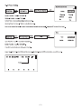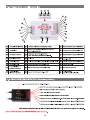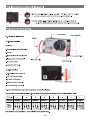
1
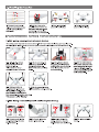
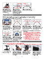
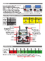
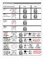
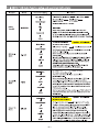
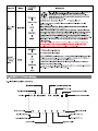
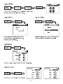
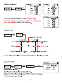
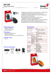
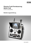
cleention
Scou tY
Auto Take off
Altitude hold mode
Object Round fly mode
One key Return To Home
Hyper IOC mode
Retractable Landing Gear
GPS telemetry
5.8G video down link
Match with DEVO F12E Radio
Quick Start Guide and Systems Flowchart
M1
M2
• Specifications:
Main Rotor Dia. : 233mm
Overall (L x W x H): 335 x 335 x 275mm
M3
Weight: 1770g(Battery included)
Takeoff Weight: <2270g
Transmitter: DEVO F12E
Receiver: DEVO-RX707(CE) / RX709(FCC)
Brushless Motor: WK-WS-34-002
Brushless ESC: WST-16AH (R/G)
Main Controller: FCS-X4
Battery: 22.2V 5400mAh Li-Po
Ground Station: GCS
2.4G Bluetooth Datalink: BT-2401A(FCC) / 2401B(FCC)
BT-2402A(CE) / 2402B(CE)
• M1/M3 rotate in clockwise, motors are the levogyrate thread.
• M2/M4 rotate in counterclockwise, motors are the dextrogyrate thread.
• When assemble the propellers, rotating direction is oppsite to the arrow direction, the directions are the same when take down the propellers.
1.0 Installing the Propellers
Q•0
Q•0
M3
M4
M2
1.1 Prepare forward propeller
(Clockwise arrow mark), counter
propeller (counterclockwise
arrow mark )
store or as
1.2 Match the arrows on the
propellers to the arrows on the
arm next to each motor. Screw
each propeller onto the motor,
secure by hand, no need for tools.
))
1.3 Prepellers assembled
(assembled skid landing)
1.4 Prepellers assembled
(unassemble skid landing)
bl the skid landing/binding the radio
2.1 Skid landing assembled(restoration/code binding)
The Landing gear is shipped in the retracted position. DO NOT try to extend the landing gear by pulling on it.
We will deploy the landing-gear the first time the system is powered, please follow these instructions carefully
Powr indicator
1:11111
0.
11.. 1,
.Its;
2.1.1 Install the fully charged
battery DO NOT turn on the
battery until later.
*Please check the charger
manual for charging instructions
2.1.2 Turn X4 on its back. The
belly and the retractable legs
should now be facing up.
MAKE SURE nothing is blocking
the legs.
2.1.5 Turn the aircraft to its
UP-right position.The Red LED
flashing will stop shortly.When it
stops, the DEVO F12E and the X4
2.1.6 After the successful binding
place the aircraft on a stable surface.
2.1.3 Put all function switches
to 0 pisition, put all trims/knobs
on Mid pisition, move the throttle
to the lowest position, then turn
on the radio power.
Power switch awe
r button
2.1.4 Turn the power switch to
"ON" position, and press on the
power button about 3-5 second
till the red LED light solid. The
undercarriage(skid landing) will
unfold automatically.
have successfully connected to each other.
* This process is called "ID binding"
2.2 Skid landing unassembled(assemle skid landing/code binding)
L1
-maw
Skid landing I I Skid landing
module A
module B
er
ee.v
•
52.2.1 Prepare two skid landing,
2.2.2 Put the skid landing into
2.2.3 Install the skid landing
skid landing module A/B, 4pcs
M2.5X20 screws.
the skid landing position.
module, and screw down the
M2.5X20 screw to fix skid landing.
• 1•
2.2.4 Skid landing installation
finished.
Power indicator
2.2.5 Put all function switches
to 0 pisition, put all trims/knobs
on Mid pisition, move the throttle
to the lowest position, then turn
on the radio power.
2.2.6 Put the aircraft on the
horizontal position, slide the
power-switch to the ON position,
then press on the power button for
about 3-5 seconds, until the green
power indicator lights up.
2.2.7 Red LED flashing till to go out
means the code binding finished.
3.0 Compass Calibration
IMPORTANT: Make sure all TRIMs are in the center position, the trim value should be "0", and that the motors are locked.
The aircraft should NOT be flashing RED. By default, the motors will automatically be locked after the ID binding process.
For more details about locking and unlocking motors, see points 6 & 7.
(
3.1 Enter the calibration mode
Do this by moving both sticks
DOWN and to the middle position
at the same time. The aircraft will
start a blinking fast RED.
a."
Ground
I
I
Mead vertical down
3.5 NOSE DOWN rotation. Rotate
the aircraft facing the nose down.
rotate smoothly in 90 deg increments.
Pausing 1 second for each 90 deg.
(0 /90/180/270/360)
4.0 - D
3.2 FORWARD rotation. Rotate
tilting the aircraft forward rotate
smoothly in 90 deg increments.
Pausing 1 second for each 90
deg.(0 / 90 / 180 / 270 / 360)
3.3 CLOCKWISE rotation. Rotate
the aircraft around the roll axis rotate
smoothly in 90 deg increments.
Pausing 1 second for each 90 deg.
(0 /90/180/270 /360)
3.4 HORISONTAL rotation. Rotate
the aircraft around the YAW axis
rotate smoothly in 90 deg increments.
Pausing 1 second for each 90 deg.
(0/90/180/270/360)
• IMPORTANT: The first couple of flights, you may expereince the
aircraft drifting,
This is normal, please continue to fly the aircraft manually, while the
system inprove the calibration, after 5-10 minutes land, lock the motors,
this will save the improved settings.
Notice: The slight drifting may continue for a couple of batteries, you
will notice significant improvement in the GPShold & stability
after 4-5 batteries.
3.6 Place the aircraft in normal
Notice: Always perform the calibration away from eletric fields and
position The rapid RED blinking will
metal surfaces.
stop This indicate that the calibration
Trivia: Different brands have different calibration processes, the
is finished Disconnect the battery to
process is typically refered to as "the Calibration Dance".
save the settings.
is brushless Gimbal installation
IMPORTANT: REMOVE the battery from the X4 while you install the gimbal
The gimbal is a high-performance eletromechanical design and should be handled with great care. AVOID using force when installing
I.
4.1 Prepare the G-3D gimbal,
M3x12 screw, spring.
4.2 Slide the gimbal unto the quik
mount rail, the gimbal shouldslide
from the front of the aircraft towards
the rear, gently move it as far back
as possible.
4.3 Install the springloaded
M3x12mm "finger screw" at the
front of the gimbal, this will
secure the gimbal.
• 2•
4.4 Connect the 9pin white data
cable to the "complex data port"
on the bottom of the X4, then
connect the cable to the back of
the G-3D gimbal.
4.5 Make sure the gimbal move freely in all directions.
The G-3D gimbal is now successfully installed.
5.0 Installing the iLook+ 1080p camera with 5.8ghz video link
'L°0k,
r1/47
5.1 Screw the short "mushroom"
antenna into the camera, use the
included wrench to gently secure
the antenna, do not use force.
5.2 Release the two M2x4 screws
securing the camera mounting
bracket.
5.3 Install the camera into gimbal,
Fix it with camera fixed frame
(ensure the gap close to the
lens), then screw the M2x4
5.4 Connect the cameras power
cable to the power port on the
G-3D gimbal controller.
screw to the camera fixed
frame again.
5.5 The iLook+ camera is now successfully
installed in your G-3D gimbal.
6.0 Motor Unlock
»scour). o, oa:ao a
After binding the DEVO F12E to the X4, Check that all trims are neutral,
the throttle stick ALL the way DOWN. the display should say 0% throttle
00
000
Check that ALL switches are in the UP position.
You can not start the motors in the GPS hold mode.
Gently push the throttle stick down and move the rudder (YAW) stick to the
1102 111110
left side. (on mode 2 radios throttle and rudder is the same stick)
dPh
You will see the RED indicator LED's will tum on, this indicate the
1.201,1,
motors are unlocked,
Mode 1(throttle stick on the right)
Mode 2(throttle stick on the left)
Be very careful at this point, as pushing the thottle up will start the motors.
You can test by pushing the stick up a little, the motors should start. For your safety, the motors will dis-arm again after 10seconds.
of
• 3•
01 .SCOUTX6 Ox WOO
10.0 Operation Instruction
Model (
is the nose direction)
Mode 1
THROTTLE
Mode 2
0 it
Up/down
—1/11.
o.-1111.
411I
PITCH
0 Tr
Forward/backward
Scout X4 nose move up/down
ROLL (lean)
Left / right
YAW (turn)
Left / right
AUTO Take Off
You should have
triple blink = 8sats
for this feature.
ARM/UNLOCK motors
in manual mode
410' • '0
aliesw
ammo.o.
411I
Ground
0
0
•
•
2
MIX
MIX Switch
to "0"
MIX
move throttle
down
• 0'
VI
2
RUDD D/R
MIX switch
to "1" position
RUDD D/R switch
to "1" position
GPS hold mode
You can fly in this mode simply
move the controls when you lei
of the control, the Scout X4 will
NOTE: You must CENTER the
throttle stick for altitude hold
MIX
MIX switch
to "1" position
Ground
ROUND FLY mode
This mode is used for
making circles around
a object of interest.
RADIUS is set in the
F12E menu by adjusting
Position 2 value for AUX3
Throttle stick
return neutral
DO NOT switch to manual before
landing it is safer to land in GPS
hold mode. swtich to manual
AFTER landing to lock motors
/--,
'FMOD 0
•
tit
2
s. MIX
\
os,
MIX switch
to "1" position
'C
Move FMOD switch to "2"
The Round Fly will start
RETURN TO HOME
MIX
Activating this feature will
casue the Scout X4 to climb
to 15m at this height it will fly
to the starting location and
411I
proceed to land.
Ground
0
•
2
Throttle stick
return neutral
1111.
• 5•
MIX switch
to "2" position
2
FMOD
Move FMOD switch to "0"
The Round Fly will stop
You can stop RTH by switching to
GPS hold MAKE SURE the throttle
stick is set to 50% when switching.
NEVER switch to MANUAL from
RTH, this can cause a crash.
11.0 DEVO F12E Radio function setup and operation instructions
Function
Switch
Transmitter setting
Instructions
Model Menu
Place aircraft on level ground -0.- Unlock Motors
`i
Device Output
Move throttle stick
to lowest position
Set MIX switch
to "0" Position
Set RUDD D/R switch to "1" Position
AUTO
Take Off
RUDD D/R
Flap
IMPORTANT:
ONLY use this function with BLUE TRIPLE blink = 8 or more
satelites, AUTO take off with less satelites may result in a crash.
RUDD D/R
AFTER completing auto-take-off, you can take control by moving
the throttle stick to 50%, then flip the RUDD D/R switch to "0" position.
Active
"0" position: Manual mode
Model Menu
"2" position: Return To Home
MIX switch to "1" position
Device Output
GPS hold
mode
MIX SW
Gear
position ( 50% ).
IF the GPS signal degrades, the X4 will automatically enter "Altitude
hold mode" note in this mode it will drift, but will hold its altitude.
After flying 50% of the battery, do NOT switch from GPS mode to
Manual, this may cause a sudden drop / crash.
You can land in GPS mode, after landing, keep the throttle stick
DOWN and switch to manual, then lock the motors.
Active
"0" Position: OFF
Model Menu
"1" Position: Not in use
"2" Position: activate Round Fly
This mode require 8 satelites locked, you should see
BLUE TRIPLE BLINK.
Before activating the round-fly mode, you should be in "GPS hold
mode" always put the throttle stick to middle position ( 50% )
The default roundfly radius is 5 meters (15 feet), You can change the
Round Fly radius by editing the AUX 3 EPA (End Point Adjustment)
on the F12E transmitter, for details on editing EPA settings, see the
F12E instruction manual.
`
Device Output
FMOD
-iii. Throttle stick return neutral
NEVER use this mode with less than 8 satelites locked, you should
see BLUE TRIPLE BLINK.
Before switching mode, always put the throttle stick to middle
MIX SW
Round Fly
Mode
"1" position: GPS hold mode
AUX3
FMOD SW
After having changed the setting, you should turn FMOD switch to "0"
position to save the data, then return to "2" position to read the new
Roundly radius.
'I'
Active
"0" position: Manual mode
Model Menu
"1" position: GPS hold mode
"2" position: Return To Home
Throttle stick return neutral -ir. MIX switch to "2" position
Device Output
Return TO
Home
The Return To Home mode, only work when you have a solid GPS
lock, it is recommend to avoid flying if GPS lock is missing.
MIX SW
Gear
After engaging Return to Home mode, lave the throttle stick at
50% (centered) do not touch any switches on the F12E radio.
You can REGAIN control of the Scout X4, make sure the throttle is
centered, then flip the MIX switch to "1" position. in a emergency like
`i
MIX SW
loss of control link between the F12e and the Scout X4, the Failsafe
system will automatically start RTH, you may not be able to interupt
a emergency RTH, simply let the aircraft continue until it lands.
Active
• 6
Function
Switch
Transmitter
setting
Model Menu
'I'
4,
AUX2
ELEV D/R
ELEV D/R
4,
Active
Model Menu
Device Output
Extend/
Retract of
Landing
Gear
4,
AUX4
GEAR
IOC or Intelligent Orientation Control mode Means the aircraft's flight direction is
only relative to the orignal take-off point (where you armed the motors).
REGARDLESS
of the actual aircraft headding, with this mode you can fly past
+
, something and pan the aircraft to frame your shot, without having to worry what
) direction the aircraft is facing.
ELEV D/R switch "0" position: IOC OFF
Device Output
Hyper IOC
Mod
Instructions
4,
GEAR SW
II
"1" position: IOC ON
The IOC mode require a strong GPS lock, you should have trible blinks on the blue
GPS indicator light.
IOC is inactive if the Scout X4 is less than 10 meter (30 feet) from the original take-off
position. (point where you armed the motors)
Fly the Scout X4 manually to past 10 meters using the GPS mode, activate the IOC mode
when you are past 10meters, the Scout X4 will now fly IOC until you change mode, you can
pan freely for video shots, when you push the stick right or left, the Scout X4 will move
sideways relative to the original take-off position. Pushing the pitch stick up will push the
Scout X4 away from you, bulling the stick back, bring the Scout X4 back to the starting point.
When flying in IOC mode, you can make the Scout X4 retun home by simply puling the
PITCH stick down.
WARNING: The IOC turns off when the aircraft get closer than lOmeters to the take off
point, be prepared for this, as the system will switch back to GPS hold mode at that
point. this switch can cause confusion if the pilot are not prepared.
"0" Position: Extend landing Gear
"1" Position: Retract landing Gear
NOTE: REMEMBER your landing gear, it is easy to forget the landing-gear when flying
FPV. its not a good idea to land on your camera. When activating the RTH (Return To
Home) system, either by the pilot of by the failsafe system.
The Scout X4 will automatically extend the landing gear to protect your camera and
make sure the Scout X4 land safely.
You can not change the landing gear after the Scout X4 have automatically extended for
landing. you must land and lock / unlock motors.
•
Active
12.0 DEVO F12E Radio Setting
12.1 Boot Screen(Main interface)
Model name
Throttle percentage value
Timer display
Model type display
Model No.
Transmission power display
01
4. Model 01 0% 00:00
Battery capacity display
Rudder trim display
Aileron trim display
Model 1 (ELEV trim)
Model 1(THRO trim)
Model 2(THRO trim)
Model 2(ELEV trim)
Left trim display
Right trim display
• 7•
12.2 Model Select
Model Select
V 01 3. Model 01
Main
interface
ENT
Main Menu UP/DN
ENT
UP/DN
Model Menu
Model Select
Model 02
02
03
Model 03
04
Model 04
05
Model 05
06 x Model 06
07
Model 07
08
Model 08
ENT
ENT
Press UP or DN button to select the stored model No.For example "Model 01",
press EXT to return back "Model Menu" after finished.
12.4 Type Select
12.3 Model Name
Model Menu
UP/DN
Model Name
ENT
Model Menu
Model Name
UP/DN
Type Select
ENT
80
Type Select
No. 01
Helicopter
Name
SCOUTX4
Glider
Press UP or DN button to select the characters which
Select the model type by R or L button, and confirmed with ENT,
need to be changed, Named model as "SCOUTX4".
once finished will return to "Model Menu" automatically
Press EXT to return "Model Menu".
12.5 Wing Type
Model Menu
UP/DN
Wing Type
ENT
Wing Type
Wing Type
V-Tai I
Dual Channels
Mate
Trim
Twin Engine
Trim
Inhibit
Inhibit
Inhibit
Inhibit
Inhibit
Inhibit
Press R or L to select "Normal", then press EXT to return "Model Menu".
12.6 Device Output
Device Output
Gear
Model Menu
UP/DN
Device Output
ENT
Flap
AUX2
Press EXT to return back "Model Menu" after finished.
AUX3
• 8
80
MIX SW
Active
RUDD D/R
Active
ELEV D/R
Active
FMOD SW
Active
1:1
Device Output
AUX4
AUX5
AUX6
AUX7
GEAR SW
Active
AUX5 KB
Active
AUX6 KB
Active
AILE D/R
Active
12.7 Sensor Setting
Sensor Setting
UP/DN
Sensor Setting
Model Menu
ENT
Status
Active
No Signal
Inhibit
Sensor Submenu
Press R or L to select "Active".
Voltage
Temperature
GPS Setting
(1)Voltage Setting
Press UP or DN to select Voltage in the Sensor Setting. Press ENT to enter Voltage interface.
Voltage
Internal: VO
Inhibit
External: V1
Active
ZEM
External: V2
Inhibit
Internal shows the Radio battery voltage.
External shows the aircraft battery voltage.
Scout X4 default setting is 21.4V, please fly back the copter when you get a warning asap.
(2) GPS Receive Setting
Press UP or DN to select GPS setting on the Sensor Setting interface, then press ENT to enter GPS Setting interface.
GPS Setting
Altitude Type
Relative
Speed Unit
Km/h
Date Type
DD-MM-YY
Time Zone
UTC+08:00
(2.1) Altitude Type setting:
Press R or L to select Absolute or Relative.
(2.2) Speed Unit setting:
Press R or L to select Km/h or Knote.
(2.3) Date Type setting:
Press R or L to select DD-MM-YY\ MM-DD-YY\ YY-MM-DD.
(2.4) Time Zone:
Press R or L to select Time Zone, then press EXT to return "Main Menu".
12.8 Reverse Switch
Main Menu
UP/DN
UP/DN
Function Menu
ENT
Reverse Switch
Elevator
Aileron
Throttle
Rudder
Gear
Flap
AUX2
AUX3
Reverse Switch
Reverse Switch
Normal
Normal
Normal
Normal
Normal
Normal
Normal
Normal
ENT
The factory default Settings interface as piture.
ENT
AUX4
AUX5
AUX6
AUX7
4
Normal
Normal
Normal
Normal
Press EXT to return back "Function Menu"
after finished.
• 9•
12.9 Servo Travel Adjust
•:7
Travel Adjust
Elevator
Travel Adjust
U100.0%
Gear
D100.0%
UP/DN
ENT
U150.0%
L100.0%
R100.0%
Flap
Throttle
H100.0%
L100.0%
AUX2
+100.0%
-100.0%
Rudder
L100.0%
R100.0%
AUX3
+5.0%
-100.0%
Aileron
Travel Adjust
Function Menu
+100.0%
-100.0%
D150.0%
Travel Adjust
Press UP or DN to select Flap channel, Press R or L to set as U150.0% and D150.0%.
AUX4
+100.0%
-100.0%
Press UP or DN to select AUX3 channel, press R or L to set +5.0%(5 means Roundly cruise flying
AUX5
+100.0%
-100.0%
AUX6
+100.0%
-100.0%
AUX7
+100.0%
-100.0%
radius is 5 metre) and -100.0%, then press EXT to return Function Menu.
12.10 Senser View
Function Menu
UP/DN
ENT
Senser View
Battery volume display
Sensor View
Timer display
'00:53 12.1V 100m4=
5.0Km/h-4
Altitude display-11 Om
Longitude display
Horizontal distance
display
-!104° 15.5123E
Move speed display
22° 06.0902N-4-Latitude display
Press R or L to select viewport display. When set the image as background, Information will be displayed on the image.
12.11 Video Setting
Video Setting
Main Menu
UP/DN
System Menu
UP/DN
Video Setting
ENT
ENT
Status
Channel
Background
Status: Press R or L to select "Active".
Channel: Press R or L to select suitable receiving video channel to iLook+ .
Background: Press R or L to select Active, Real-time image could be set as background in Main Menu.
Press EXT to show full screen image in Main Menu.
• 10 •
-71
1/32
Active
12.12 Timer Setting
Stick Position Switch
Off
Main Menu
UP/DN
UP/DN
Model Menu
Stick Position Switch
ENT
Switch
ENT
Switch: Press R or L to select "SPSO SW".
SPSO SW
Channel
Throttle
Position
L94%
Channel: Press R or L to select "Throttle".
On
Position: Press L to set percentage(Suggest setting is L94%).
Higt
On setting: Press R or L to select "High" as rocker direction of on.
Move up and down of the throttle to check if the direction of the switch is set correctly. Then press EXT to return "Main Menu".
Timer
Main Menu
UP/DN
UP/DN
Function Menu
Timer
ENT
Type
Stopwatch
Switch
SPSO SW
ENT
Type: Press R or L to select stopwatch or countdown.
Switch: Press R or L to select "SPSO SW".
Press EXT to return back main interface after finished.
Usage: Toggle the throttle up to L94% to start the time, toggle the throttle down to L94% to stop the time, press DN to reset.
01
Model 01 0% 00:00 Th
Timer
0 0 0 0 0 0
• 11 •
13.0 FCS-X4 Main controller guideline
pm' po.P4
esn 160dt1LVO ssvewoT
i
r
(JeUenton
M1
Or. -II M2
-Al M3
-41 M4
M5
11. ms
0
AUX 3 IP
AUX 21.
AUX 1 IP
GEAR IP
RUDD IP
THRO I1P
ELEV ►
RILE 11.
CHECK POWER IP
FCS—X4
Main controller
E
110-4 M7
MADE IN CHINA
DATA SUS IP
JUMP PORT. IP
TT,
®
To roundly cruise flight mode
0
To hyper IOC
®
To one key to take off
®
®
To check voltage(connect with power board)
0
Used for data transmission-connect the PPM OUT
port of BT-2401A/2402A
(it
Connect with fifth way brushless ESC
0
Connect with forth way brushless ESC
0
Connect with third way brushless ESC
qo
Connect with second way
brushless ESC
®
Jumper port, when regular receiver is
need, insert random equipped bind plug pls.
Control Mode Switch
a
To link LED
0
To control Rudder
CD
To link GPS module(red white blue black four color cable)
0
Connect with first way brushless ESC
0
To control Throttle
(3
Connect with eighth way brushless ESC
0
Upgrade channel
®
To control Elevator
(forward & backward)
@
Connect with seventh way brushless ESC
@
Data communcation port
®
To control Aileron
(leftward & rightward)
0,
Connect with sixth way brushless ESC
4-31
To link Compass
(red black double color cable)
14.0 DEVO RX707(CE)/RX709(FCC) Receiver guideling
Telemetry connector(connect with single white line)
DATA BUS: Used for data transmission-connect the PPM IN port of BT-2401A/2402A
AUX1: One key to take off(no need to connect)
DATA BUS
TELEMETRY CON
AUX1
cleVention
AUX2
RX ,VO V
AUX3
AUX4
AUX2: Hyper IOC(no need to connect)
AUX3: Roundly cruise flight mode(no need to connect)
AUX5
CE
AUX6
MATE IN CHINA AUX]
AUX4: Connect the servo of landing skid-connect the PWM3 IN port of BT-2401A/2402A
AUX5: Connect gimbal Roll singal cable-connect the PWM 2 IN port of BT-2401A/2402A
UX6: Connect gimbal PIT singal cable-connect the PWM 1 IN port of BT-2401A/2402A
AUX7: Connect camera controller/Clear fix ID code(When clear fix ID code is need, insert random equipped bind plug pls).
Attention: DEVO RX707(CE) and DEVO RX709(FCC)have the same port
• 12 •
15.0 Instruction for knobs of G-3D gimbal
ff,
e
PIT: Set up gimbal tilt angle(control angle range -135°- 90°), please refer to the mid-point
as starting point, proper adjust the knob in counterclockwise direction.
ROLL: Set up gimbal rolling angle(control angle range 45°- 45°), please refer to the
mid-point as starting point, proper adjust the knob in counterclockwise direction.
16.0 iLook+ Camera Setting
Shutter Button
Video/Photo Switch
16.1 Pictures illustration
16.2 Specifications
(1) Video
a. Video Resolution: 1920 x1080 Full HD
b.FPS: 30
c. Micro High Speed SD card: Max 64G
Power port(DC 7V-15V)
d. Imaging Sensor: 3,000,000 Pixels
Indicator(Red light)
Micro SD card slot
e. Video Format: MOV
f. Photo: 4032x3024 Pixels
•Video 1920 1080P/30FPS
• Photo 4032»3024 Pixels
• Support 5.8G image transfer
•TV-out function
(2) 5.8G wireless
a. 5.8G wireless image transmission
b.FCC Output Power5200mW
c. CE Output Power525mW
Channel code switch
d. CE Bind B section: 8 channels
e.FCC Bind B section: 4 channels
16.3 iLook+(FCC/CE) camera transmitting channel selection
There are 8 different channels can be selected. You can choose the best frequency channel according to the image quality as bellow:
Channel
1
2
3
4
5
6
7
8
Frequency
5866MHz
5847MHz
5828MHz
5809MHz
5790MHz
5771MHz
5752MHz
5733MHz
3
3
3
3
3
3
3
code
position
(off/on)
[3
2
1
ggg
0N
g
2
1
1
0N
2
1
0N
2
1
lir I I
0N
Note: Only transmitting channel 2, 4, 6, 8 are available for the iLook/iLook+(FCC).
• 13 •
2
1
li I
'ON
2
1
2
1
I PI
1 il
0N
0N
I
2
1
1
I
ON
16.4 Video and Photo user guide
Warm tips:
(1) Micro SD card must be inserted to the iLook+ camera before connecting the power, and took off after disconnecting the power.
(Recommend to use high speed SD card)
(2) Insert MICRO SD card, the camera is powered on, the red indicator light indicates the camera is initialized, the red light goes out indicates the
camera enters standby mode initialization is complete.
(3) Insert MICRO SD card, the camera is powered on, if the red indicator light blinks rapidly means formatting it is necessary.pls stir video/ photo
switch to a position press shutter last for 5 sec.format after the completion of the proposed re-energized camera.
(1) Video instruction
(1.1) Radio Operation
Switch
Transmitter
setting
Model Menu
(1) It's a must to turn the switch of iLook+ to "
a " position.
(2) Start video: turn the AILE D/R switch from "0" position to "1" position, wait for 1-2 seconds, then return
/
Device Output
/
AILE D/R
Instructions
AUX7
4'
AILE D/R
to "0" position, the camera will start to video (the red indicator keeps flash with an interval of 0.5 second).
The red indication of video status can be seen on the transmitter.
Stop video: turn the AILE D/R switch from "0" position to"1" position, wait for 1-2 seconds, then return
to "0" position, the camera will stop video (the red indicator lights out). And the red indication of video
status can not be seen on the transmitter.
(3) Make sure that the video recorded will not be saved in the SD card if you haven't finished
the "stop video" operation.
Active
(1.2) Manual Operation
Turn the Video/Photo Swich to
U first please, press the shutter button once, iLook+ camera starts to Video(the Red indicator flash for 0.5sec
interval); Press the shutter button again, iLook+ camera stops video(The Red indicator light out).
(2) Photo instruction
Please Turn the video/photo switch to Ci, Press the shutter button once, iLook camera Will take a photo (The Red indicator blinks once then light
out), press the shutter button again, it will take another photo.
17.0 Conne charger instructio
Slide the power switch to "ON" position when charging, press the power button for 3-5 seconds till the power indicator keeps on.
Power button
g;;t1';4-Power switch
I I 14-Power indicator
I
For details, please refer to iMAX B6 user manual.
• 14 •