1
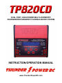
DUAL PORT, HIGH-POWER MULTI-CHEMISTRY
CHARGER/DISCHARGER/CYCLER/BALANCER SYSTEM
INSTRUCTION/OPERATION MANUAL
www.ThunderPowerRC.com
1
TABLE OF CONTENTS
NOTICE, WARNING AND CAUTION ..................................................................................................................... 4
NOTICE .......................................................................................................................................................... 4
WARNING...................................................................................................................................................... 4
CAUTION ....................................................................................................................................................... 4
BOX CONTENTS ................................................................................................................................................. 4
INTRODUCTION ................................................................................................................................................. 5
FEATURES .......................................................................................................................................................... 6
SPECIFICATIONS ................................................................................................................................................ 7
INPUT POWER SOURCE AND CONNECTION........................................................................................................ 7
Input Current Max ......................................................................................................................................... 7
Input Power Low Voltage Cutoff .................................................................................................................... 7
Input Power Source Connection..................................................................................................................... 8
INPUT AND OUTPUT POWER ............................................................................................................................. 8
BATTERY CONNECTIONS .................................................................................................................................... 9
BALANCER CONNECTIONS (for LiPo/LiIon/LiFe batteries) ................................................................................... 9
OPERATING INFO............................................................................................................................................. 11
Button Functions ......................................................................................................................................... 11
+/– buttons ................................................................................................................................................. 11
PORT button ................................................................................................................................................ 11
MODE button .............................................................................................................................................. 11
ENTER button .............................................................................................................................................. 11
CHARGE MODE ................................................................................................................................................ 11
Memory Profiles .......................................................................................................................................... 12
Battery Chemistry Type ............................................................................................................................... 12
Battery Cell Count........................................................................................................................................ 12
Battery Capacity .......................................................................................................................................... 13
Charge Current Rate .................................................................................................................................... 13
Balancing ON/OFF (for LiPo/LiIon/LiFe batteries) ......................................................................................... 14
Delta Peak Sensitivity (for NiCd/NiMH batteries) ......................................................................................... 15
Charging the Battery .................................................................................................................................... 15
Charging LiPo/LiIon/LiFe (A123) Batteries .................................................................................................... 15
Data Monitoring During Charging ................................................................................................................ 16
Charging Complete/End ............................................................................................................................... 16
Charging LiPo Batteries for use in Series on Separate Ports .......................................................................... 17
Charging Split LiPo Batteries up to 16S on Separate Ports ............................................................................ 17
DISCHARGE MODE ........................................................................................................................................... 19
Discharge Current Rate ................................................................................................................................ 20
Discharge Voltage Cutoff ............................................................................................................................. 21
Discharging the Battery ............................................................................................................................... 21
Data Monitoring During Discharging ............................................................................................................ 21
Discharging Complete/End .......................................................................................................................... 22
Cooling Fans During/After Discharge ........................................................................................................... 22
2
CYCLE MODE ................................................................................................................................................... 22
Cycle Order.................................................................................................................................................. 23
Cycle Number .............................................................................................................................................. 23
Cycling the Battery ...................................................................................................................................... 23
Data Monitoring During Cycling ................................................................................................................... 23
Cycling Complete/End ................................................................................................................................. 23
STORAGE MODE .............................................................................................................................................. 24
Storage Charging/Discharging the Battery ................................................................................................... 24
Data Monitoring During the Storage Process ............................................................................................... 24
Storage Complete/End................................................................................................................................. 25
SETTING DATA (SETTINGS) MODE .................................................................................................................... 25
Charge End Voltage ..................................................................................................................................... 25
Power Distribution....................................................................................................................................... 26
Input Power LVC/Input Current Max ............................................................................................................ 27
Cycle Pause Time ......................................................................................................................................... 27
Charge Capacity Limit .................................................................................................................................. 27
Safety Timer ................................................................................................................................................ 27
Temperature Cutoff ..................................................................................................................................... 28
Key Beep ..................................................................................................................................................... 28
End Beep Duration....................................................................................................................................... 28
Temperature Unit ........................................................................................................................................ 28
DATA VIEW MODE ........................................................................................................................................... 28
Battery Internal Resistance .......................................................................................................................... 29
To Measure Battery Internal Resistance....................................................................................................... 30
To Measure Individual Cell Internal Resistance ............................................................................................ 31
Charge/Discharge Mode Data ...................................................................................................................... 31
Cycle Charge/Discharge Capacity Data ......................................................................................................... 31
Peak Voltage and Discharge Average Voltage Data ...................................................................................... 31
Individual Cell Voltage Data (for LiPo/LiIon/LiFe Batteries) ........................................................................... 31
Real-Time Input Voltage and Output Voltage Data ....................................................................................... 32
Internal Temperature Data .......................................................................................................................... 32
ERROR MESSAGES AND TROUBLESHOOTING ................................................................................................... 32
FIRMWARE UPDATES....................................................................................................................................... 33
WARRANTY, SUPPORT AND SERVICE ............................................................................................................... 34
3
NOTICE, WARNING AND CAUTION
NOTICE
All instructions, warranties, and other collateral documents are subject to change at the sole discretion
of Advance Energy, Inc. dba Thunder Power RC. For up-to-date product literature, visit
www.ThunderPowerRC.com or call 702-228-8883.
WARNING
Read the ENTIRE instruction manual to become familiar with the features/functions of the
charger before operating. NEVER LEAVE THE CHARGER UNATTENDED DURING USE. Failure
to observe/operate the charger properly can cause damage to the charger, battery, personal
property and/or cause serious injury.
CAUTION
Attempting to charge batteries different that those specified in this manual can result in excessive heat
and other related product malfunctions, which can lead to property damage and/or injury. Please
contact Thunder Power RC (TPRC) or an authorized retailer with compatibility questions.
As TPRC has no control over use, setup, final assembly, modification or misuse, no liability shall be
assumed nor accepted for any resulting damage or injury. By the act of use, setup or assembly, the
user accepts all resulting liability.
If you as the Purchaser or user are not prepared to accept the liability associated with the use of this
Product, you are advised to return this Product immediately in new and unused condition to the place
of purchase.
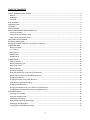
BOX CONTENTS
4
INTRODUCTION
The TP820CD is a powerful and advanced dual port multi-chemistry charger, discharger, cycler and
balancer system. With up to 800 watts of total charging power the TP820CD is equipped with two
ports that function completely independently to charge, discharge and cycle a wide variety of
1-8S LiPo, LiIon and LiFe (A123) batteries, as well as 1-24 cell NiCd and NiMH along with 6-30V Pb
(lead-acid) batteries. The built-in 2-8S LiPo/LiIon/LiFe (A123) cell balancers, one for each port, and
included balance connector adapter boards are readily compatible with all Thunder Power balance
connectors and the JST-XH balance connectors found on many other batteries.
The dual port TP820CD offers the convenience and flexibility of two separate chargers in a single yet
incredibly compact case as a result of its advanced power conversion technology and
Thunder Power RC exclusive design. Each port is capable of charging at rates up to 20 amps, even
simultaneously depending on input power and charge settings, offering the ability to charge many of
the latest-generation LiPo batteries at ultra-fast rates up to 6C and beyond. This means the
TP820CD is well-equipped to quickly charge batteries up to 8S on each port, as well as ‘split’ batteries
equipped with interconnect leads up to 16S by using both ports simultaneously.
Popular examples of the powerful charging capabilities of the TP820CD are the ability to charge
two 5S 5000mAh batteries, one on each port simultaneously at rates up to 4C, or two 6S 5000mAh
batteries at rates more than 3.5C, to have a complete 10S or 12S 5000mAh battery setup charged in
as little as 15 minutes or less time. That’s even faster than single port chargers rated at higher
current and wattage output, without the need for cumbersome parallel charging and an even more
powerful power supply, and without giving up the added convenience and flexibility that independent
dual port charge, discharge and cycling functionality offers. And because each port functions
independently you can even mix and match charge, discharge or cycling duties of a LiPo motor power
battery and a NiMH transmitter battery, a NiCd receiver battery and a lead-acid field box battery or
just about any other combination you might have.
Additional features include built-in data logging and viewing on the large, class-leading and
easy-to-read 48-character blue backlit LCD screen, internal resistance (IR) measurement and an
advanced Storage Mode function to automatically charge or discharge LiPo/LiIon/LiFe (A123)
batteries as needed. Other great features also include dual computer-controlled cooling fans and
temperature protection, an attractive and extremely durable aluminum case, plus the ability to install
future firmware updates available for free download from www.ThunderPowerRC.com using a
standard mini USB cable. Best of all these incredible features are all available at a value that’s hard
to beat while being fully supported and backed by Thunder Power RC with industry-leading warranty
support and service.
5
FEATURES
Powerful all-in-one dual port charger, discharger and cycler system with built-in
LiPo/LiIon/LiFe (A123) cell balancers that offer maximum safety, performance and
easy-to-see individual cell voltages
The included balance connector adapter boards (2pcs) allow the built-in balancers to be
used with 2-8S Thunder Power-compatible balance connectors as well as the JST-XH
balance connectors found on many other brand batteries from Align, Dynamite®, E-flite®,
ParkZone® and more
Convenient and flexible dual (two) port design charges, discharges and cycles
1-8S LiPo/LiIon/LiFe (A123), 1-24 cell NiCd/NiMH and 6-30V Pb (lead-acid) batteries on
each port independently or simultaneously
More than double the charging power, up to 800 watts total (400 watts per port), of other
similar class chargers with selectable charge rates from 0.2 amps up to 20 amps for each
port
The perfect choice for safe and ultra-fast charging at rates of 3-6C and beyond for the
latest-generation LiPo batteries
Charge two 5S or 6S 5000mAh batteries at rates up to 4C for 10S or 12S battery setup
charge times of as little as 15 minutes or less* – even faster than single port chargers that
require cumbersome parallel charging and a more powerful power supply
Advanced Storage Mode function for LiPo/LiIon/LiFe (A123) batteries will automatically
charge or discharge as needed to achieve storage level voltage
24 user-programmable memories plus built-in data logging and viewing with
internal resistance measurement, battery voltage, input voltage, temperature and more
Fully-adjustable charge capacity limit, per cell end voltage and low voltage cutoff settings
for all chemistries to maximize safety, charge and discharge performance
Durable and compact aluminum case with dual computer-controlled cooling fans and a
large, class-leading and easy-to-read 48-character blue backlit LCD screen
Wide input voltage range from 10.5-28.0V for higher efficiency and power output when
using 24.0-28.0V power supplies
Adjustable output power distribution per port, input power current limiting and low voltage
cutoff settings to maximize performance while also protecting the charger and input power
supply
Future firmware updates can be downloaded for free from www.ThunderPowerRC.com
when new features, battery chemistry and other updates are made available and are easily
uploaded to the charger using a standard mini USB cable
Full industry-leading warranty and support from Thunder Power RC
*With 24.0-28.0V input and depending on state of charge before charging begins
6
SPECIFICATIONS
Type: Dual Port Multi-Chemistry DC Charger/Discharger/Cycler with Integrated Balancers
Battery Cell Counts/Types (Per Port): 1-8S LiPo/LiIon/LiFe (A123), 1-24 cell NiCd/NiMH and 6-30V
Pb (lead-acid)
Balancer (Per Port): Integrated for 2-8S LiPo/LiIon/LiFe (A123) with balance connector adapter
board for Thunder Power and JST-XH connectors
Input Power: 10.5-28.0V DC (40 amps max)
Charge Power: 800 watts max (400 watts max per port) w/24.0-28.0V input (see later in this manual
for additional information regarding input and output power)
Charge Current (Per Port): 0.2 to 20 amps in 0.01 amp increments
Charge Voltage: 50% storage and adjustable end voltage for LiPo/LiIon/LiFe (A123), adjustable delta
peak sensitivity and end voltage for NiCd/NiMH and end voltage for Pb (Lead Acid)
Discharge Power: 100 watts max (50 watts max per port)
Discharge Current (Per Port): 0.2 to 10 amps in 0.01 amp increments
Discharge Voltage: Adjustable low voltage cutoff for LiPo/LiIon/LiFe (A123), NiCd/NiMH and Pb
(lead-acid)
Cycles: 1 to 15 times with data stored for all cycles
Memories: 24 user-programmable
Firmware: User-updatable using USB
INPUT POWER SOURCE AND CONNECTION
The TP820CD (charger) is designed and built to be powered from a 10.5-28.0V DC power source.
This can include a single 12V Pb/lead-acid battery, two 12V Pb/lead-acid batteries connected in
series for 24V or a quality AC to DC power supply with stable 10.5-28.0V DC output.
Input Current Max
The maximum input current can be set from 10.0-40.0A in order to prevent damage to the power
source and/or charger. This means you can limit the maximum current the charger can pull from the
power source per the maximum capabilities of the source as needed. For example, if you are using a
power supply that is capable of outputting 25.0A max you should adjust the Input Current MAX setting
to 25.0A to ensure the charger is not able to pull more than 25.0A from the power supply. You can
adjust this setting in the charger by powering it on and pressing the MODE button once to scroll to the
Setting Data (Settings) menu, then press the + or – buttons to scroll to the appropriate menu and
adjust the setting accordingly. Or, in order to obtain maximum output power (per input voltage) for
charging, you must use a power supply capable of delivering up to 40.0A.
Input Power Low Voltage Cutoff
You can also set the Input Power LVC (Low Voltage Cutoff). This is the input voltage at which the
charger will stop charging/discharging in order to prevent overloading/over-discharging the input
power source. This is particularly beneficial when charging from a 12V Pb/lead-acid car battery as it
allows you to maintain enough voltage/power in the battery to still start the car after using the charger.
You can adjust this setting in the charger by pressing the MODE button once to scroll to the Setting
Data (Settings) menu, then press the + or – buttons to scroll to the appropriate menu and adjust the
setting accordingly. We recommend setting this value to between 10.5V and 11.0V for typical use, or
7
in the case that you will be loading the input power source considerably (so the voltage will drop more
significantly under load even though there is still sufficient capacity remaining in the 12V battery for
example) you can set this as low as 10.0V. However, keep in mind that dropping the voltage under
load to as a low as 10.0V (or even 10.5V under some loads) could result in discharging a 12V battery
input power source low enough that it will not start the car when needed.
Input Power Source Connection
The input power leads for the charger are equipped with 4mm bullet connectors compatible with most
typical female ‘banana plug’ receptacles. You can connect these directly to the outputs of many AC to
DC power supplies, or you can also connect them to the included alligator clips for more convenient
connection to Pb/lead-acid batteries. However, especially when charging at or near maximum
input/output power levels, you must ensure the bullet connectors/alligator clips are making excellent
contact with the power source in order to minimize resistance and prevent voltage/power
loss/damage.
After connecting the charger to the input power source with proper polarity the charger will power on
accordingly. At this point you will briefly see the ‘Welcome’ screen indicating the charger model and
the version of firmware currently installed in the charger.
Please also note that in some cases if the connection to the input power source is not ‘clean’
the welcome screen may not show and instead only part of the default Charge Mode screen
will show. This will typically happen when connecting the charger to a power source that is
already ‘on’ so we suggest powering down the source before connecting the charger. Also, if
this occurs simply disconnect the charger from the power source, then re-connect ensuring
that you achieve a solid/clean connection during the process.
INPUT AND OUTPUT POWER
The charger will automatically adjust the output power level available based on the input voltage,
current, output voltage, etc. and at no time can the input current exceed 40.0A max. As a result you
can obtain higher/maximum output power when using higher voltage power sources that provide 24.028.0V. However, it is still possible to obtain relatively high levels of output power using more common
10.5-15.0V power sources.
Here also is a quick way to help determine the approximate amount of input power your chosen power
source can supply:
Input Voltage (under load) (V) x Input Current (A) = Input Power (W)
For example:
12V x 25A = 300W
12V x 40A = 480W
24V x 25A = 600W
27V x 40A = 1080W
The input power level will dictate the charger’s output power level capability in total based on charger
efficiency (typically ~85-93% depending on input/output voltage). And in turn the output power level
capability will dictate the maximum charge current/voltage capability accordingly.
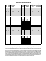
Please see the chart provided separately for a quick reference of the maximum output power
levels/charge current for LiPo batteries based on the listed input voltage and current (and please note
that these values are approximate and may vary +/– slightly depending on input voltage of the power
8
source under load, ambient temperatures, state of charge/voltage level of the battery being charged,
etc.).
Also, for those interested in achieving maximum output power (800W total) we recommend using a
27.0-28.0V, 35-40A power supply for maximum efficiency (especially when charging multiple 6S
22.2V LiPo batteries for example). One such power supply we’ve used with excellent success is the
IOTA Engineering DLS-27-40. With a typical output voltage of 27.2V and the capability to deliver up
to 40A, this power supply can deliver upwards of 1100W to the charger allowing for maximum output
(800W) with some headroom to spare (also works well with two TP820CD chargers running at high
power levels up to ~500W each).
BATTERY CONNECTIONS
The charger is equipped with typical female ‘banana plug’ receptacles for each port that are
compatible with most male banana plugs and 4mm bullet connectors. We suggest using gold 4mm
bullet connectors, like those found on the included battery connection leads, especially when charging
at rates above 5 amps.
You can also install the connector(s) of your choice on the included battery connection leads and/or in
many cases you can purchase pre-made ‘charge leads’ equipped with banana or 4mm bullet
connectors, wire leads and connectors compatible with the connectors installed on the batteries you
will be charging/discharging. Also, wire leads that are too long and/or not large enough gauge
(AWG/GA) for the applicable charge/discharge current will become warm/hot which can damage the
charger and/or result in errors in battery charging/discharging (i.e. – ‘false peaks’ when charging
NiCd/NiMH batteries, etc.). These details in mind, we recommend keeping the length of the wire
leads as short as possible (preferably 12”/305mm long max). We also recommend using 10 to 14
AWG wire leads when charging at rates 10 amps and higher, minimum 16 AWG at rates up to 10
amps and minimum 18 AWG at rates up to 5 amps.
Please also be certain to connect all batteries with the proper polarity as marked on the faceplate
label and further identified by the colored rings around the banana plug receptacles (red is +/positive
and black is –/negative). And in the event that you do connect the battery with incorrect polarity the
error message ‘Battery Reverse Polarity’ (or ‘Battery Polarity Inversion’ in earlier version firmware) will
show on the screen. However, in order to prevent all possibility of damage to the charger and/or
battery you should always exercise care to ensure proper polarity when connecting batteries.
Also, DO NOT connect the battery to the charger when the charger is powered off. The
charger should always be powered on before connecting the battery.
BALANCER CONNECTIONS (for LiPo/LiIon/LiFe batteries)
The TP820CD is equipped with built-in balancers for LiPo/LiIon/LiFe (A123) cells/batteries. There is
an independent balancer for each port as marked on the faceplate label and you should ALWAYS
use the balancers when charging LiPo/LiIon/LiFe batteries for maximum safety and battery
performance/longevity. The balancers, working in conjunction with the charger, perform functions
similar to the safety circuits found in the LiPo/LiIon/LiFe cells/batteries for cell phones, laptop and
other electronic devices to prevent over-charging that can result in fire causing damage and/or
personal injury. They do this by ensuring the voltages of cells within LiPo/LiIon/LiFe batteries are
closely equalized/balanced by discharging the higher voltage cells to closely match the lower voltage
cell(s) in the battery. This prevents over-charging any cell(s) that may have a higher voltage during
the charge process, or, in the event that the balancer cannot balance the cell(s) in time to prevent
exceeding the ‘CHG End Voltage’ setting (for any cell), the charger will automatically reduce the
charge current rate and/or end the charge process entirely as needed.
9
Please also note that due to the high-power charging capabilities of the TP820CD it is not
designed to charge through the balance connectors/leads of LiPo/LiIon/LiFe batteries. These
connectors/leads are typically limited to maximum charge/discharge rates of only 2-4 amps
versus the up to 20 amp charge rate capability of the TP820CD. As a result you MUST connect
the main power AND balance connector leads to the charger in order to charge through the
main power and balance through the balance connector leads accordingly.
The 9-pin Thunder Power type connectors for each balancer are located on the sides of the charger.
When viewing each connector straight on (with the top/face of the charger pointed upwards) the main
ground/negative (–) connector (pin) is located on the far left while the positive (+) connector is located
on the far right. And while it is possible to connect Thunder Power 4-pin and 6-pin balance
connectors from batteries and extensions to these connectors directly (always aligning the main
ground/negative wire to the far left), to prevent any issues with connection location, polarity and
fatigue of the connection between the 9-pin connectors and the charger board internally, we
recommend always using the included balance connector adapter boards instead.
To use the included balance connector adapter boards simply insert the male 9-pin connector into the
female 9-pin connector for each balancer. The connectors are ‘keyed’ to prevent reverse polarity
connection, and each balance connector adapter board is equipped with balance connectors
compatible with all 2S 7.4V to 8S 29.6V LiPo/LiIon/LiFe batteries equipped with Thunder Power and
JST-XH balance connectors. And in the event that you must connect batteries that are not equipped
with TP or JST-XH balance connectors, there are additional balance connector adapter leads (i.e. –
TP to JST-EH, etc.) available from many sources. Please also note that the balance connector
adapter boards are also available separately if needed:
TP8SAB-TPJXH
2S to 8S Thunder Power/JST-XH Balance Connector Adapter Board
The following accessories for Thunder Power balance connectors are also available:
TP4P8
TP6P13
TP4P10E
TP6P10E
TP6P4E
4-Pin Balance Connector w/8" 22GA Color Coded Wires
6-Pin Balance Connector w/13" 22GA Color Coded Wires
4-Pin Balance Connector Extension w/10" Color Coded Wires
6-Pin Balance Connector Extension w/10" Color Coded Wires
6-Pin to 4-Pin Balance Connector Adapter
After connecting the balance connector adapter board to the charger/balancer you can connect the
balance connector from the battery to the appropriate mating connector, ensuring proper keying of the
connectors and polarity, on the board accordingly. And please note that unless you are using the
correct adapters/connections to charge multiple batteries in series and/or parallel (contact Thunder
Power RC directly for more information on series/parallel charging if needed) you must NOT connect
more than one battery to the balance connector adapter board. If you connect multiple batteries
incorrectly or connect one battery with incorrect polarity it is possible to damage the traces and/or the
pins/connectors on the balance connector adapter board (and such damage is not covered under
warranty).
10
OPERATING INFO
Button Functions
+/– buttons
The +/– buttons allow you to scroll up/down through menus before and during charging/discharging.
These buttons also allow you to change values/settings for options after they have been selected
(typically when flashing after pressing the ENTER button).
PORT button
The PORT button allows you to toggle/switch the port (1 or 2) you are currently viewing. You can
toggle/switch between each port any time before and during charging/discharging by pressing the
PORT button. Also, the port you are currently viewing is always indicated by a 1 or 2 as seen in the
upper right hand corner on all screens.
MODE button
The MODE button functions only before/when not charging/discharging. Pressing the MODE button
will allow you to scroll between the three available modes:
Charge/Discharge/Cycle/Storage Modes
Setting Data Mode
Data View Mode
ENTER button
The ENTER button allows you to select and validate values/settings for options that can be changed
(using the +/– buttons to change) before and during charging/discharging. Pressing and holding the
ENTER button also allows you to start and stop charging/discharging.
CHARGE MODE
After powering on the charger properly the first mode always shown by default is the ‘Charge Mode’.
This is the mode that allows you to set the memory profile number, battery chemistry type, number of
cells, battery capacity limit, charge current rate, balancing on/off for LiPo/LiIon/Life or the delta peak
value for NiCd/NiMH. It’s also important to note that all of these settings must be set in this
mode/screen before changing to the discharge, cycle or storage modes (these settings cannot
be changed/set in those modes).
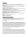
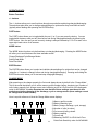
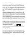
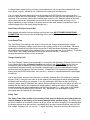
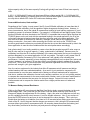
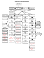
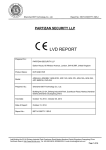
Here is a quick reference of what the Charge Mode screen displays:
1
2
6
3
7
4
1) Memory profile number
2) Battery chemistry type
3) Mode (charge, discharge, cycle, storage)
4) Number of cells (in series)
5) Port currently being viewed
6) Battery capacity
7) Current rate
8) Balancing ON/OFF for LiPo/LiIon/LiFe or
Delta Peak Sensitivity value for NiCd/NiMH
5
8
11
Memory Profiles
You can set a total of 12 memory profiles per port (24 total). This is a convenient feature as it allows
you to set the typical charge, discharge, cycle and storage mode profiles for specific batteries to save
you time versus having to always change the settings when charging/discharging different
configurations and chemistries of batteries.
To scroll through the available memory profiles, while on the Charge Mode screen simply press the
ENTER button once. The memory profile number will begin to flash and you can use the +/– buttons
to scroll through the profiles accordingly. And again, you can set up to 12 profiles per port (24 profiles
in total), however, we do recommend setting the same profiles, in the same order, for both ports if you
have no more than 12 different configurations/chemistries of batteries as it will allow you to select the
profile for your batteries on either or both ports simultaneously with ease.
Battery Chemistry Type
The TP820CD is capable of charging/discharging LiPo, LiIon, LiFe (A123), NiCd, NiMH and Pb (leadacid) batteries. Each of these chemistries/types of batteries is charged in a different way and
you MUST select the correct chemistry/type in order for the charger to charge/discharge
safely. Failure to select the correct chemistry/type and settings per the battery being
charged/discharged can result in damage to the battery or fire causing damage and/or
personal injury. If you are unsure of the battery chemistry/type, and the correct settings that
must be used for safe and correct charging/discharging, DO NOT attempt to charge/discharge
the battery. Instead, please contact the manufacturer of the battery for more information first.
To select the correct battery chemistry/type, while on the Charge Mode screen simply press the
ENTER button twice. The battery chemistry/type will begin to flash and you can use the +/– buttons to
scroll through them accordingly. After selecting the correct chemistry/type you can press the ENTER
button to select the other adjustable values, or wait approximately 5 seconds until the chemistry/type
stops flashing to begin the charge process or to scroll through the other modes (discharge, cycle and
storage).
Battery Cell Count
The TP820CD is capable of charging/discharging 1S (3.7V) to 8S (29.6V) LiPo, LiIon and LiFe (A123)
batteries, as well as 1-24 cell NiCd and NiMH along with 1S (2V) to 15S (30V) Pb (lead-acid)
batteries. After selecting the correct battery chemistry/type you MUST select the correct cell
count for the battery you will be charging/discharging. Failure to select the correct cell count
per the battery being charged/discharged can result in damage to the battery or fire causing
damage and/or personal injury. If you are unsure of the battery cell count DO NOT attempt to
charge/discharge the battery. Instead, please contact the manufacturer of the battery for more
information first.
To select the correct battery cell count, while on the Charge Mode screen simply press the ENTER
button three times. The battery cell count will begin to flash and you can use the +/– buttons to
increase/decrease the cell count accordingly. After selecting the correct cell count you can press the
ENTER button to select the other adjustable values, or wait approximately 5 seconds until the cell
count stops flashing to begin the charge process or to scroll through the other modes.
12
Battery Capacity
For added safety and ease of use, the TP820CD features a function that allows you to set the battery
capacity. This function allows you to enter the capacity of the battery you’ll be charging so the
charger can automatically set a 1C (1 x Capacity) charge rate. In general most supported battery
chemistries/types can be charged safely and successfully at a 1C rate so this feature makes for the
easiest possible setting and use especially if you are not confident in taking advantage of and/or
aware of the max charge rate capability of the battery you’ll be charging.
This function also adds an additional level of safety as it helps to ensure, in conjunction with the CHG
(Charge) Capacity Limit function found in the Setting Data (Settings) menu, that even if the charger
does not terminate/end charging correctly per the battery chemistry/type, that it will still end the
charge when the set capacity has been reached.
These details in mind you should ALWAYS set the battery capacity correctly. To set the correct
battery capacity, while on the Charge Mode screen simply press the ENTER button four times. The
battery capacity will begin to flash and you can use the +/– buttons to increase/decrease the capacity
accordingly. After setting the correct capacity you can press the ENTER button to select the other
adjustable values, or wait approximately 5 seconds until the cell count stops flashing to begin the
charge process or to scroll through the other modes.
Charge Current Rate
After setting the battery capacity limit correctly, the charger will automatically set the charge current
rate to 1C. In the case of a 5000mAh battery, it will set the charge current to 5.00A. And again, in
general most supported battery chemistries/types can be charged safely and successfully at a 1C rate
so we suggest charging at the 1C rate especially if you are not confident in taking advantage of and/or
aware of the max charge rate capability of the battery you’ll be charging.
Or, if you are interested in charging at a rate higher (or lower) than 1C you can adjust the charge
current rate accordingly. However, it is important to note that if you charge at a current rate that
is too high it can result in damage to the battery or even fire causing damage and/or personal
injury. If you are unsure of the maximum safe charge rate of the battery DO NOT charge at a
rate higher than 1C or please contact the manufacturer of the battery for more information.
And to set the charge current rate, while on the Charge Mode screen simply press the ENTER button
five times. The charge current rate will begin to flash and you can use the +/– buttons to
increase/decrease the current rate accordingly. After setting the charge current rate per your
preference you can press the ENTER button to select the other adjustable values, or wait
approximately 5 seconds until the current rate stops flashing to begin the charge process or to scroll
through the other modes.
Also, before starting the charge process the maximum charge current that can be set (if it is
less than 20.0A, which is the max charge current rate for each port) is automatically calculated
by the charger based on the voltage of the input power source and the estimated voltage of
the battery being charged based on the cell count you have selected. This is calculated using
the discharged voltage of the battery (i.e. ~3.3V per cell for LiPo batteries) so it is possible to set the
charge current rate to the maximum rate possible.
And if you have set the charge current rate to the maximum rate possible, after starting the
charge process the charger will automatically adjust the current rate, per the actual voltage of
the battery at any given time, to maintain (and not exceed) the maximum output power level
(wattage). For example, in the case of charging a 6S 22.2V 5000mAh LiPo battery and when using a
13
27.0-28.0V/35-40A power supply for maximum input/output power, before the charge process has
started you will be able to set the charge current rate to 20.0A max. However, if the battery is
currently at more than 20.0V the charger will then adjust the current rate automatically between 20.0A
and approximately 15.8A as needed to ensure it does not exceed the 400W maximum output power
level of each port. And when the battery nears/reaches the end of the Constant Current (CC) phase
of the charge around 25.2V (4.2V per cell) the current rate will reduce accordingly throughout the
Constant Voltage (CV) phase of the charge process and until the charge is complete.
Also, after the charge process has started (and if you have not already set the charge current
rate to the maximum rate possible) you can actually increase the charge current rate by up to
25% (i.e. – from 10.0A to 12.5A) or to the maximum charge current rate possible based on the
actual voltage of the battery and power level of each port; whichever comes first . To do this,
simply press the ENTER button once immediately (or any time) after the charge process has been
started (and the ‘Battery Check Please Wait…’ check is complete) and the current rate will begin to
flash. You can then use the + button to increase (or the – button to decrease) the current rate
accordingly.
These details in mind, please also see the chart provided separately for a quick reference of the
maximum output power levels/charge current rate settings for LiPo batteries based on the listed input
voltage and current (and please note that these values are approximate and may vary +/- slightly
depending on the input voltage, output current, power level of the power source under load, ambient
temperatures, state of charge/voltage level of the battery being charged, etc.).
Balancing ON/OFF (for LiPo/LiIon/LiFe batteries)
As noted in further detail in the BALANCER CONNECTIONS section of this manual, the TP820CD is
equipped with built-in balancers for LiPo/LiIon/LiFe (A123) cells/batteries and you should ALWAYS
use the balancers when charging LiPo/LiIon/LiFe batteries for maximum safety and battery
performance/longevity. The balancers, working in conjunction with the charger, perform functions
similar to the safety circuits found in the LiPo/LiIon/LiFe cells/batteries for cell phones, laptop and
other electronic devices to prevent over-charging that can result in fire causing damage and/or
personal injury. They do this by ensuring the voltages of cells within LiPo/LiIon/LiFe batteries are
closely equalized/balanced by discharging the higher voltage cells to closely match the lower voltage
cell(s) in the battery. This prevents over-charging any cell(s) that may have a higher voltage during
the charge process, or, in the event that the balancer cannot balance the cell(s) in time to prevent
exceeding the ‘CHG End Voltage’ setting (for any cell), the charger will automatically reduce the
charge current rate and/or end the charge process entirely as needed.
The balancers can also further ensure that you’ve set the cell count correctly, and as a result
we strongly recommend keeping the balancing turned ON at all times. Please also note that
when balancing is turned ON you MUST connect the balance connector of the battery to the
balance connector adapter board (which must be connected to the balancer/charger) BEFORE
you start the charge process otherwise you’ll encounter a Battery Type Error warning.
However, if you understand the associated risks, accept full responsibility and choose to charge
LiPo/LiIon/LiFe batteries without balancing/using the built-in balancers, it is possible to turn the
balancing OFF.
To turn the balancing ON/OFF, while on the Charge Mode screen simply press the ENTER button six
times. The balancing status will begin to flash and you can use the +/– buttons to turn it ON or OFF.
After turning the balancing ON or OFF per your preference you can press the ENTER button to select
the other adjustable values, or wait approximately 5 seconds until the status stops flashing to begin
the charge process or to scroll through the other modes.
14
Delta Peak Sensitivity (for NiCd/NiMH batteries)
When the charger has been set to charge NiCd or NiMH chemistry/type batteries you can also set the
delta peak sensitivity value. This is the difference in voltage when the NiCd/NiMH battery reaches
peak voltage/fully charged voltage and is used to complete/end charging of NiCd/NiMH batteries
accordingly.
Generally speaking a higher delta peak sensitivity value will result in more charge or even potential
over-charge, however, in many cases a slight amount of over-charge and the resulting warming of the
cells/battery is desired to ensure the highest possible performance. Slightly warm cells/batteries
(approximately 5-15° Fahrenheit above ambient) are also a good indication that they are fully
charged, however, it is recommended to use the lowest delta peak sensitivity value that allows the
cells/battery to be fully charged and to not stop charging prematurely (typically referred to as ‘false
peaking’).
NiCd cells/batteries typically require a higher delta peak sensitivity value (~10-20mV per cell) to reach
full charge while NiMH batteries require a lower value (~1-10mV per cell). However, in the case of
either chemistry the actual value that works best will depend on many factors including the capacity,
condition and internal resistance (IR) of the cells/battery, IR of the charge leads/connectors, charge
current rate, ambient temperature and more. As a result it is always suggested to start with a lower
value and to increase the value accordingly as needed to achieve slight warming of the cells after the
charge process had been completed/ended.
To adjust the delta peak sensitivity value, while on the Charge Mode screen simply press the ENTER
button six times. The value will begin to flash and you can use the +/– buttons to increase or
decrease the value accordingly. After setting the value per your preference you can press the ENTER
button to select the other adjustable values, or wait approximately 5 seconds until the value stops
flashing to begin the charge process or to scroll through the other modes.
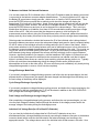
Charging the Battery
After setting the correct battery chemistry type, cell count, capacity and current, and connecting the
battery to the charger properly, you are ready to begin charging. To begin charging simply press and
HOLD the ENTER button for a few seconds (please also note that during charging you can press and
hold the ENTER button to end the charge process).
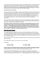
From there the charger will check the battery
while displaying the following screen:
If the battery is connected properly and the charger confirms that all other parameters are correct,
charging will begin automatically.
Charging LiPo/LiIon/LiFe (A123) Batteries
When charging LiPo/LiIon/LiFe batteries, if the voltage of any cell (when balancing is ON) or all cells
are too low (below ~3.3V) the charger may charge at a rate lower than the charge current rate set
before the charge process began and until the voltage is considered safe/high enough to charge the
battery normally. Or, if the voltages of all cells are OK the charger will increase the current until it
reaches the appropriate charge current rate. And in either case charging will be in the Constant
Current phase, as indicated by the ‘CC’ located in the middle of the upper line on the screen, until the
cells reach approximately 4.20V.
15
At that point, and as long as cells are balanced within 0.03V (when balancing is ON), charging will
switch to the Constant Voltage phase as indicated by the ‘CV’ that will show in placed of ‘CC’. Or, if
any cell is imbalanced by more than 0.03V charging will instead switch from the Constant Current
phase to the Extended Balance phase, as indicated by the EB that will show in place of CC/CV. This
will allow the charger to adjust the charge current rate as needed to ensure the cells are balanced to
within 0.03V (or closer) before the charge process is ended automatically.
Data Monitoring During Charging
Throughout (and after) the charge process you can view/monitor various data. On the main charging
screen you will see the elapsed duration of the charge process, the capacity that’s been ‘charged’ into
the battery, the charge current rate and the voltage of the battery. You can also use the +/ – buttons
to switch between the various screens to see the available data.
For example, when charging a LiPo/LiIon/LiFe battery and on the charging screen simply press the +
button once and you will see the individual cell voltages (when balancing is turned ON). Please also
note that while only the second (hundredths) place after the decimal is shown due to the space
available on the screen (in order to show voltages for up to 8 cells on a single screen), the
charger is measuring and calculating the voltages/balance by using to the third (thousandths)
place. This means when you see a cell at 3.80V and another at 3.82V the cells are likely as
close as 3.804V and 3.816V but the values on the screen are being rounded up and down
accordingly.
If you press the + button a second time you’ll again see the elapsed time, as well as the internal
temperature of the charger and the peak voltage the battery has reached through the duration of the
charge process so far. Then, pressing the + button a third time will show the elapsed time along with
the input voltage from the power source. This can be particularly useful, especially when pushing the
input power source near its limits and/or when using a 12V (or 24V) Pb/lead-acid battery, to ensure
the voltage is not dropping too much when under load during the charging process. Please also note
that while only the second (hundredths) place after the decimal is shown the charger is measuring
and calculating the input voltage by using to the third (thousandths) place. This means the input
voltage reading may appear to move up and down slightly, however, as long as it is not fluctuating by
more than ~0.03V the input voltage/power is indeed smooth and stable.
And when charging a NiCd/NiMH/Pb (lead-acid) battery, the first time you press the + button you will
again see the elapsed time along with the average voltage of the battery that would show after a
discharge process has ended. Pressing the + button a second time will also show the internal
temperature of the charger and the peak voltage the battery reached during the charge process while
pressing the + button a third time will show the elapsed time along with the input voltage from the
power source.
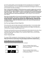
Charging Complete/End
Charging will be complete/end automatically when the battery capacity has been reached, per delta
peak (for NiCd/NiMH batteries) or when the appropriate per cell CHG (Charge) End Voltage has been
reached (for LiPo/LiIon/LiFe and Pb batteries). When this occurs you will see the following screen:
16
From there you can press the ENTER button once to display the data from the charge process, as
well as use the +/ – buttons to scroll through other screens, including the screen that features the
Battery.IR function to check the Internal Resistance (IR) of the battery and/or individual cells by
pressing the ENTER button (while on those screens). Or, on most other screens you can press the
ENTER button to exit the charge process completely.
Charging LiPo Batteries for use in Series on Separate Ports
The dual port flexibility and convenience of the TP820CD makes it an excellent choice for charging
LiPo batteries up to 8S 29.6V separately on each port for use in series up to 16S 59.2V in large-scale
airplanes, helicopters and other applications. Other popular examples include charging 5S and 6S
4400-5000mAh batteries for use in series as 10S and 12S setups in F3A, F3C and 3D helicopter
applications at rates up to 4C for charge times of as little as 15 minutes or less.
Charging each battery that will be used in series separately on each port is quick and easy to do.
Simply connect one battery to each port and set them to charge at the same rates. And while in some
cases there may be slight variations in the time it takes to charge each battery (meaning one may
finish charging before the other), because the two ports are calibrated very closely, the batteries
should be charged to almost exactly the same level which can also save substantial time over having
the two ports attempt to charge/balance together simultaneously.
Also, due to potentially slight differences in the condition/performance of each battery, we suggest
checking to ensure that both batteries are charged to within approximately 0.05V (or less) after the
charge process is complete for each. From there the batteries are ready to use in series, and we
suggest, as with all LiPo batteries, to discharge no more than 80-85% capacity to ensure maximum
performance and longevity.
Charging Split LiPo Batteries up to 16S on Separate Ports
The dual ports of the TP820CD are also an excellent choice for charging ‘split’ batteries that feature
interconnect leads (for transport/shipping as non-dangerous/non-hazardous goods when the leads are
left disconnected) up to 16S 59.2V. The split/interconnect configuration of most of these batteries
allows them to be charged as two lower cell count batteries. For example an appropriately configured
10S split battery with interconnect leads, such as all Thunder Power RC G4 and G6 10S 33005000mAh batteries, can be charged as two separate 5S batteries. And in the case of 10S 5000mAh
split batteries in particular, you can charge each 5S ‘half’ on each port at rates up to 4C for charge
times of as little as 15 minutes or less for the complete 10S battery.
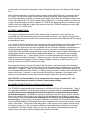
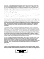
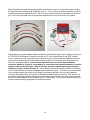
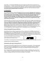
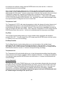
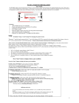
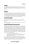
Using the dual ports of the TP820CD to charge split batteries requires only a few additional
accessories and setup steps to make it relatively quick and easy. And using a Thunder Power RC
10S 5000mAh battery equipped with the factory-installed 4mm bullet connectors on the interconnect
leads and a female Deans Ultra Plug connector on the main power leads as an example, the following
accessories are required (as shown in the photo below):
10-14 AWG charge lead with a male Deans Ultra Plug connector; 1pc
10-14 AWG negative charge lead with a male 4mm bullet connector on both ends; 1pc
10-14 AWG positive charge lead with a male 4mm bullet connector on one end and a female
4mm bullet connector on the other end; 1pc
TP6P10E (6-Pin Balance Connector Extension w/10" Color Coded Wires); 2pcs (OPTIONAL)
17
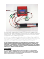
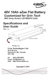
Beginning with the charge lead equipped with a male Deans connector, connect the negative lead to
the negative female ‘banana plug’ receptacle of port 1. Then connect the positive lead to the positive
female banana plug receptacle of port 2. Next, connect the male end of the separate positive lead to
port 1 and one of the male ends of the separate negative lead to port 2 as shown in the photo.
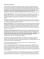
With a balance connector adapter board connected to each balancer port on the charger, connect 1pc
of TP6P10E (6-Pin Balance Connector Extension w/10" Color Coded Wires) to the 4-5S Thunder
Power connector on each board (this step is optional as you can also connect the balance connector
leads from the battery directly to the adapter boards, however, the relatively short lead lengths can
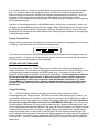
make this somewhat difficult). Now the most important step is to ensure that the balance
connector labeled as ‘Group A’ on the battery is connected to the extension/balance connector
adapter board connected to port 1 (this is because the main negative/ground wire lead from
the battery is also connected to port 1). Then connect the balance connector labeled as ‘Group B’
to the extension/balance connector adapter board connected to port 2. The battery is now connected
to the charger properly and ready to be charged (and please note that if you mix up the balance
connector connections per port it should not damage the battery/charger, however, it will result in an
error when attempting to charge with either port because the port will ‘see’ the main power leads and
balance connector leads from two different ‘halves’ of the battery). See the photo for reference of the
correct connection/wiring arrangement including the battery.
18
Now you will need to configure each port to charge a 5S LiPo battery at the charge current rate of
your preference. We suggest configuring one of the ports correctly, then moving to the second port to
configure it correctly. Then start the charging process on the last port you configured then switch to
the other port and start the charge process accordingly.
And while in some cases there may be slight variations in the time it takes to charge each half of the
battery (meaning one may finish charging before the other), because the two ports are calibrated very
closely, the halves should be charged to almost exactly the same level which can actually save
substantial time over having the two ports attempt to charge/balance the halves together
simultaneously.
Also, due to potentially slight differences in the condition/performance of each battery, we suggest
checking to ensure that both halves are charged to within approximately 0.05V (or less) after the
charge process is complete for each. From there the battery is ready to use as 10S (after connecting
the interconnect leads), and we suggest, as with all LiPo batteries, to discharge no more than 80-85%
capacity to ensure maximum performance and longevity.
DISCHARGE MODE
The TP820CD is able to discharge batteries in order to check capacity or for other reasons as
needed. It’s capable of discharging at rates up to 10.0A and 50W per port, and keep in mind that
aside from the discharge current rate and per cell voltage cutoff that can be set in the Discharge
Mode, the cell count must be set in the Charge Mode.
19
After setting the correct cell count in the Charge Mode, wait until none of the adjustable values are
flashing, then press the + button once to enter the Discharge Mode.
Discharge Current Rate
In general most supported battery chemistries/types can be discharged safely and successfully at a
1C to 4C rate so we suggest discharging at no higher than these rates especially if you are not aware
of the max discharge rate capability of the battery you’ll be discharging. That said, because the
TP820CD is capable of discharging at rates up to 10A/50W, in many cases it will not be possible to
discharge batteries, especially those above approximately 3S 11.1V 5000mAh, at even a 1C rate.
However, especially in the case of lower capacity batteries for which you can exceed a 4C
discharge rate, it is important to note that if you discharge at a current rate that is too high it
can result in damage to the battery or even fire causing damage and/or personal injury. If you
are unsure of the maximum safe discharge rate of the battery DO NOT discharge at a rate
higher than 1C to 4C or please contact the manufacturer of the battery for more information.
And to set the discharge current rate, while on the Discharge Mode screen simply press the ENTER
button once. The discharge current rate will begin to flash and you can use the +/– buttons to
increase/decrease the current rate accordingly. After setting the discharge current rate per your
preference you can press the ENTER button to select the other adjustable values, or wait
approximately 5 seconds until the current rate stops flashing to begin the discharge process or to
scroll through the other modes.
Also, before starting the discharge process the maximum discharge current that can be set (if
it is less than 10.0A, which is the max discharge current rate for each port) is automatically
calculated by the charger based on the estimated voltage of the battery being discharged and
the cell count you have selected (~3.6V per cell for LiPo batteries). So in most cases it is not
possible to set the discharge current rate to the 10.0A max for cell counts more than 1S 3.7V for
LiPo/LiIon/LiFe, and even if you do set the rate to 10.0A for higher cell batteries, it will exceed the
maximum discharge power level (wattage) capabilities of each port and the charger will reduce the
rate accordingly after the discharge process has started.
And after the discharge process has started you can actually increase the discharge current
rate by up to 25% (i.e. – from 5.00A to 6.25A) or the maximum discharge current rate possible
based on the actual voltage of the battery and power level of each port; whichever comes first.
To do this, simply press the ENTER button once immediately (or any time) after the discharge
process has been started (and the ‘Battery Check Please Wait…’ check is complete) and the current
rate will begin to flash. You can then use the + button to increase (or the – button to decrease) the
current rate accordingly.
And in the event that the discharge current rate and voltage of the battery being discharged,
as well as the ambient temperature and internal temperature of charger, result in over-heating
the charger (above ~130° F) during the discharge process, you will see the ‘Over Temperature
Please Wait…000°’ warning including the current internal temperature of the charger. The
charger will automatically pause the discharge until it cools to approximately 100° F, then it
will resume the discharge automatically. And although the discharge current rate and voltage
of the battery may not exceed the maximum discharge power rating of the port, especially in
the case of higher capacity batteries that take longer to discharge and create more heat in the
charger for a longer period of time, you may indeed need to reduce the discharge current rate
in order to prevent the over temperature and pause.
20
These details in mind, please also see the chart provided separately for a quick reference of the
estimated maximum discharge power levels/discharge current rate settings for LiPo batteries based
on the current rate and estimated voltage of the battery (and please note that these values are
approximate and may vary +/- slightly depending on ambient temperatures, state of charge/voltage
level of the battery being discharged, etc.).
Discharge Voltage Cutoff
You can set the per cell voltage cutoff that will complete/end the discharge process automatically
using this setting. However, especially in the case of LiPo/LiIon/LiFe batteries, it is important
that you DO NOT over-discharge the batteries to a voltage that is too low as it can result in
damage to the battery. If you are unsure of the safest discharge voltage cutoff for the battery
DO NOT discharge the battery or please contact the manufacturer of the battery for more
information.
Here also are some general suggestions of the per cell voltage cutoff to use for each battery
chemistry/type to prevent over-discharge/damage:
LiPo/LiIon
LiFe
NiCd/NiMH
Pb/lead-acid
3.3-3.5V per cell when discharged at rates of 1-4C
2.6-2.8V per cell when discharged at rates of 1-4C
0.9-1.0V per cell when discharged at rates of 1-4C
1.6-1.7V per cell when discharged at rates of 1-4C
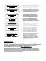
Discharging the Battery
After setting the correct battery chemistry type and cell count in the Charge Mode, then also the
correct discharge current rate and voltage cutoff in the Discharge Mode, connect the battery to the
charger properly and you are ready to begin discharging. To begin discharging simply press and
HOLD the ENTER button for a few seconds (please also note that during discharging you can press
and hold the ENTER button to end the discharge process).
From there the charger will check the battery
while displaying the following screen:
If the battery is connected properly and the charger confirms that all other parameters are correct,
discharging will begin automatically.
Data Monitoring During Discharging
Throughout (and after) the discharge process you can view/monitor various data. On the main
discharging screen you will see the elapsed duration of the discharge process, the capacity that’s
been discharged from the battery, the discharge current rate and the voltage of the battery. You can
also use the +/ – buttons to switch between the various screens to see the available data.
For example, when discharging a LiPo/LiIon/LiFe battery and on the discharging screen simply press
the + button once and you will see the individual cell voltages (when balancing is turned ON). If you
press the + button a second time you’ll again see the elapsed time, as well as the internal
temperature of the charger and the peak voltage of the battery at the beginning of the discharge
process. Pressing the + button a third time will show the elapsed time in addition to the input voltage
from the power source.
21
And when discharging a NiCd/NiMH/Pb (lead-acid) battery, the first time you press the + button you
will again see the elapsed time along with the average voltage of the battery that will be shown when
the discharge process has ended. Pressing the + button a second time will also show the internal
temperature of the charger and the peak voltage of the battery at the beginning of the discharge
process while pressing the + button a third time will show the elapsed time in addition to the input
voltage from the power source.
Discharging Complete/End
Discharging will be complete/end automatically when the battery reaches the appropriate per cell
voltage. When this occurs you will see the following screen:
From there you can press the ENTER button once to display the data from the discharge process, as
well as use the +/ – buttons to scroll through other screens, including the screen that features
Battery.IR to check the Internal Resistance (IR) of the battery and/or individual cells (for
LiPo/LiIon/LiFe and with the balancer connected) by pressing the ENTER button while on that screen.
Or, on most other screens you can press the ENTER button to exit the charge process completely.
Cooling Fans During/After Discharge
During the discharge process one or both fans may come on at low or high settings to help control the
internal temperature of the charger. In some cases, even after the discharge process has
completed/ended the fans will continue to run even when the internal temp has reached near ambient
temperature. If this happens you can power the charger off then on again and the fans will remain off
until the next charge/discharge process begins (and only if needed).
Please also note that there are plans to offer enhanced fan control and the ability to set temperature
cutoffs in future firmware releases.
CYCLE MODE
The TP820CD is capable of charging/discharging batteries automatically by cycling them up to 15
times. This can be particularly useful for testing and/or rejuvenating NiCd/NiMH batteries and please
note that we DO NOT recommend cycling LiPo/LiIon/LiFe batteries as it comes at great risk
unless you monitor all charge/discharge cycles in person fully and set the discharge cutoff
voltage to a level high enough to prevent over-discharge. Even still it has been shown that,
unlike other chemistries such as NiCd/NiMH, it is typically not possible to rejuvenate LiPo/LiIon/LiFe
cells/batteries through charge/discharge cycling.
Please also keep in mind that aside from selecting the order of charge->discharge (CHG->DCHG) or
discharge->charge (DCHG->CHG) and the number of cycles, you must set the chemistry type, cell
count, capacity and charge current rate in the Charge Mode, and the discharge current rate and the
per cell voltage cutoff in the Discharge Mode. After setting the correct values in the Charge Mode,
wait until none of the adjustable values are flashing, then press the + button once to enter the
Discharge Mode. After setting the correct values in this mode, wait until none of the values are
flashing then press the + button one more time to enter the Cycle Mode.
22
Cycle Order
You can select the cycle order, charge->discharge (CHG->DCHG) or discharge->charge (DCHG>CHG), using this setting. To change the order simply press the ENTER button once then use the +/
– buttons to adjust the order accordingly.
Cycle Number
This allows you to set the number of cycles the charger will automatically perform from 1 to 15. To set
the number simply press the ENTER button twice and use the +/ – buttons to adjust the number of
cycles accordingly.
Cycling the Battery
After setting the correct battery chemistry type, cell count, capacity and charge current rate in the
Charge Mode, and the correct discharge current rate and voltage cutoff in the Discharge Mode along
with the cycle order and number of cycles, you are ready to begin cycling. To begin cycling simply
press and HOLD the ENTER button for a few seconds (please also note that during cycling you can
press and hold the ENTER button to end the charge process).
From there the charger will check the battery
while displaying the following screen:
If the battery is connected properly and the charger confirms that all other parameters are correct,
cycling will begin automatically.
Data Monitoring During Cycling
Throughout (and after) the cycling process you can view/monitor various data. On the main cycling
screen you will see the elapsed duration of the current charge or discharge process, the capacity
that’s been charged into/discharged from the battery, the charge/discharge current rate and the
voltage of the battery.
Also, it will be possible to identify whether the charger is charging or discharging for the current cycle,
as well as the number of the current cycle, by looking at the ‘C00D’ info located in the middle of the
upper line on the screen. When the ‘C’ is flashing the charger is charging, and when the ‘D’ is
flashing the charger is discharging. And the number of the current cycle, 01 through 15, will be
displayed between the C and D accordingly.
You can also use the +/ – buttons to switch between the various screens to see the other available
data. For example, when cycling a NiCd/NiMH battery, the first time you press the + button you will
again see the elapsed time along with the average voltage of the battery that will be shown when the
discharge process has ended. Pressing the + button a second time will also show the internal
temperature of the charger and the peak voltage of the battery during the charge or at the beginning
of the discharge process.
Cycling Complete/End
Discharging will be complete/end automatically when the battery reaches the appropriate per cell
voltage. When this occurs you will see the following screen:
23
From there you can press the ENTER button once to display the data from the cycling process, as
well as use the +/ – buttons to scroll through other screens, and on most other screens you can press
the ENTER button to exit the charge process completely. It’s also important to note that the data from
the completed cycling process can also be viewed in the Data View mode after exiting the process
and before the next charge/discharge process begins.
STORAGE MODE
The TP820CD features an advanced Storage Mode that automatically discharges and/or charges the
battery for safe and healthy storage. For added reference you should NEVER store LiPo batteries
at full charge for more than few hours at most (and they should be stored at temps of 40-75° F
whenever possible to prevent swelling and/or loss of performance/capacity). Instead you
should use the Storage Mode to automatically charge or discharge them to approximately 50%
capacity (~3.85V per cell), especially if the battery is more than 50% charged and will not be
used in the next few hours.
Please also keep in mind that you must set the chemistry type, cell count, capacity and charge current
rate in the Charge Mode and the discharge current rate in the Discharge Mode. These are the values
used by the charger to automatically charge/discharge the battery accordingly in the Storage Mode.
In the case of LiPo/LiIon batteries, the charger will automatically charge (if the voltage is below
approximately 3.85V per cell) or discharge (if the voltage is above approximately 3.85V per cell) the
battery to approximately 3.85V per cell, and for LiFe batteries to approximately 3.3V per cell. For
NiCd/NiMH batteries the charger will automatically discharge them to the discharge voltage cutoff set
in the Discharge Mode, then charge them to 50% of the capacity set in the Charge Mode.
Storage Charging/Discharging the Battery
After setting the correct battery chemistry type, cell count, capacity (for NiCd/NiMH batteries) and
charge current rate in the Charge Mode, and the correct discharge current rate and voltage cutoff (for
NiCd/NiMH batteries) in the Discharge Mode, you can begin the storage process by simply pressing
and HOLDING the ENTER button for a few seconds (please also note that during the storage process
you can press and hold the ENTER button to end the process accordingly).
From there the charger will check the battery
while displaying the following screen:
If the battery is connected properly and the charger confirms that all other parameters are correct, the
storage process will begin automatically.
Data Monitoring During the Storage Process
Throughout (and after) the storage process you can view/monitor various data. On the main storage
screen you will see the elapsed duration of the current charge or discharge process, the capacity
that’s been charged into/discharged from the battery, the charge/discharge current rate and the
voltage of the battery.
Also, it will be possible to identify whether the charger is charging or discharging by looking at the
‘CHG’ or ‘DCHG’ info located in the middle of the upper line on the screen. When ‘CHG’ shows the
charger is charging, and when ‘DCHG’ shows the charger is discharging.
24
You can also use the +/ – buttons to switch between the various screens to see the other available
data. For example, when in the storage process for a LiPo/LiIon/LiFe battery simply press the +
button once and you will see the individual cell voltages (when balancing is turned ON). And if you
press the + button a second time you’ll again see the elapsed time, as well as the internal
temperature of the charger and the peak voltage of the battery during the charge or at the beginning
of the discharge process.
And when in the storage process for a NiCd/NiMH battery, the first time you press the + button you
will again see the elapsed time along with the average voltage of the battery that will be shown when
the discharge process has ended. Pressing the + button a second time will also show the internal
temperature of the charger and the peak voltage of the battery during the charge or at the beginning
of the discharge process.
Storage Complete/End
Storage will be complete/end automatically when the battery reaches the appropriate per cell voltage
or capacity. When this occurs you will see the following screen:
From there you can press the ENTER button once to display the data from the storage process, as
well as use the +/ – buttons to scroll through other screens, and on most screens you can press the
ENTER button to exit the storage process completely.
SETTING DATA (SETTINGS) MODE
The Setting Data mode of the TP820CD allows you to set the various default settings/data for a
variety of functions. You can reach the Setting Data mode from any of the Charge, Discharge, Cycle
or Storage Mode screens by pressing the MODE button once. From there you can use the +/ –
buttons to scroll through the available screens/menus accordingly. It’s also important to note that
the follow settings/data apply the same to both ports (and all memory profiles) and can be
viewed/changed when either port is selected: Power Distribution, Input Power LVC, Input
Current MAX and Temperature Unit. All other settings/data apply to each port (and in some
cases the memory profile too) individually and must be viewed/changed according to the
specific port.
Charge End Voltage
The ‘…..CHG End Voltage’ sets the end voltage per cell the charger will achieve before
completing/ending the charge process. This value can be set for all chemistry types, however, you
must have the chemistry you would like to set the value for selected in the Charge Mode in order for
that chemistry to show appropriately in the charge end voltage screen/menu. It’s also important to
note that the charge end voltage value can be set PER MEMORY PROFILE so you can fine-tune
the end voltage of the battery, just as you can the chemistry type, capacity and charge current rate.
This is helpful because sometimes batteries of the same cell count and capacity, but different internal
resistance/performance levels, may charge to slightly different end voltages when using the same
charge end voltage value. In those cases it may be helpful to have the same chemistry type, cell
count, capacity and charge current rate values but different charge end voltage values in two different
memory profiles. To adjust this value simply press the ENTER button once and the value will flash.
Then use the +/– buttons to increase/decrease the value per your preference and/or the guidelines
listed below.
25
For LiPo batteries, and LiIon batteries with a nominal voltage of 3.7V per cell (and full charge
voltage of 4.2V per cell), you can set the charge end voltage up to 4.24V per cell. And although the
maximum recommended charge end voltage per cell is 4.235V, due to slight variations in the
components and calibration of each charger, resistance of charge leads and cells/batteries, ambient
conditions and more, it is possible that when the value is set to 4.24V it will not actually exceed
4.235V per cell when checked with a calibrated Digital Volt Meter (DVM). We first recommend
charging with the value set to 4.20V per cell then checking the actual voltage per cell with a calibrated
DVM (DO NOT use a non-calibrated DVM for this check as it can read the voltage too high or too low
and cause you to adjust the value incorrectly). If the voltage of each cell is between 4.19V and 4.21V,
we suggest leaving the setting as is. Or, if the voltage is even higher or lower you can adjust the
value +/– 0.01V and test again until you achieve the desired charge end voltage for your particular
charger and batteries (and again, this is adjusted independently per port and per memory profile for
each port). Please note that this adjustment is to allow for advanced fine-tuning/calibration of
the charge end voltage, however, if you do not have a calibrated DVM and/or experience with
this type of checking and tuning we suggest leaving the value at 4.20V per cell regardless.
For LiIon batteries with a nominal voltage of 3.6V per cell, or if you’d like to charge your LiPo
batteries to approximately 90% charged in order to extend their cycle life and shorten charge
times, typically the recommended full charge voltage is 4.1V per cell. This in mind you can use the
LiPo Charge Mode and charge end voltage setting, adjusted to 4.10V, to charge the appropriate LiIon
batteries (or LiPo batteries to approximately 90% charged) accordingly.
LiFe batteries typically have a recommended full charge voltage of 3.60V per cell. However,
you can set the charge end voltage up to 3.80V per cell for the same reasons as noted for LiPo
batteries above. Also, please note that this adjustment is to allow for advanced fine-tuning/calibration
of the charge end voltage, however, if you do not have a calibrated DMV and/or experience with this
type of checking and tuning we suggest leaving the value at 3.60V per cell regardless.
For Pb/Lead-acid batteries, we suggest setting the charge end voltage to the value per cell
recommended by the battery manufacturer (as these values do vary from manufacturer to
manufacturer). However, a value of approximately 2.25-2.30V per cell (~13.5-13.8V for a typical 6S
12V battery) is typically a safe, conservative value for all Pb/lead-acid batteries.
For NiCd/NiMH batteries you will typically use the Delta Peak Sensitivity value, set in the Charge
Mode, to ensure proper peak/full charging of the batteries accordingly. However, in case you set the
delta peak sensitivity value too high, you can also set the charge end voltage to complete/finish the
charge process instead. In this case we suggest setting the charge end voltage value to 1.60-1.80V
per cell because if the value is set too low it will not allow for proper peak/full charging of the batteries.
Power Distribution
When using an input power source that is only capable of supplying less current than the 40A
required for maximum power (wattage) output per a given input voltage you can adjust the distribution
of power between the ports to achieve up to max power from a single port (as the actual input voltage
and current allow) rather than splitting it evenly and between both ports (as is the case with the default
setting of 50% and 50%).
For example, with an input power source that supplies 12V and 30A max under load, if the Power
Distribution is set to 50% and 50%, the maximum wattage available from each port will be
approximately 150W max (300W total). However, because each port is capable of up to 250W max
with 12V input, you can actually bias the power distribution to give one port more power versus the
other in order to achieve the 250W max for one and 50W for the other (achieving the same 300W total
but with more/max output power capability for one of the ports). This is particularly useful if you need
26
to charge higher capacity/cell count motor power batteries on one port and lower capacity/cell count
motor power, receiver, transmitter, etc. batteries on the other port simultaneously.
You can adjust the power distribution levels by pressing the ENTER button once and using the +/–
buttons to adjust the levels accordingly. And please also see the chart provided separately for a quick
reference of the maximum output power levels/charge current for LiPo batteries based on the listed
input voltage and current (and please note that these values are approximate and may vary +/–
slightly depending on input voltage of the power source under load, ambient temperatures, state of
charge/voltage level of the battery being charged, etc.).
Input Power LVC/Input Current Max
More detailed information on these settings can be found in the INPUT POWER SOURCE AND
CONNECTION section found near the beginning of this manual. Please refer to that section for more
information.
Cycle Pause Time
The Cycle Pause Time setting is the amount of time that the charger pauses between charge>discharge or discharge->charge cycles when in the cycling process of the Cycle Mode. Generally
speaking you should set the pause time to an amount of time that allows the battery to adequately
cool between charging/discharging cycles in order to prevent damage due to over-heating. To set the
Cycle Pause Time, simply press the ENTER button once and use the +/– buttons to
increase/decrease the amount of time as needed.
Charge Capacity Limit
The CHG (Charge) Capacity Limit percentage, in conjunction with the Battery Capacity function found
in the Charge Mode (see the Battery Capacity sub-section of the Charge Mode section for more
information), adds an additional level of safety to help ensure that even if the charger does not
complete/end charging correctly per the battery chemistry/type it will still complete/end the charge
process when the set capacity has been reached. To adjust the CHG Capacity Limit percentage,
simply press the ENTER button twice, then use the +/– buttons to increase/decrease the percentage
accordingly.
And in some cases, because many users do not typically discharge their LiPo batteries in particular
beyond 75-85%, it may be even safer to set the capacity limit percentage to match the approximate
discharge level accordingly (for example, if you only discharge to 80% then set the limit to 80%).
However, please keep in mind that if the capacity limit percentage is set to a level below 90-100% it is
possible that the charger will complete/end charging when it reaches the capacity limit rather than
completing/ending the charge appropriately per the chemistry/type (i.e. – delta peak for NiCd/NiMH,
CC/CV to CHG End Voltage for LiPo/LiIon/LiFe, etc.), especially if you discharge by a higher
percentage than the capacity limit percentage.
Safety Timer
The Safety Timer offers another level of safety to help prevent dangerous over-charge that can
result in damage to the battery or fire causing damage and/or personal injury. The safety timer
will limit the amount of time that a function can go on, and in the case of charging, it will complete/end
the charge process when the time limit is reached even if the other features/functions (such as CHG
End Voltage, Capacity Limit, etc.) do not. To adjust the Safety Timer time limit from the minimum to
27
the maximum time allowed, simply press the ENTER button once, then use the +/– buttons to
increase/decrease the time accordingly.
Also, if most of your charging will be done at a 1C rate (typically requiring 45-75 minutes for an
approximately 70-90% discharged battery to be fully charged), we recommend setting the time to
approximately 90-100 minutes. However, please keep in mind that if the time limit is set too low that it
is possible the charger will complete/end charging when it reaches the time limit rather than
completing/ending the charge appropriately per the chemistry/type (i.e. – delta peak for NiCd/NiMH,
CC/CV to CHG End Voltage for LiPo/LiIon/LiFe, etc.), especially if the battery was discharged further
than expected and/or is charged at too low of a current rate.
Temperature Cutoff
The Temperature CUTOFF is the internal temperature at which the charger will reduce the amount of
charging/discharging power or stop charging/discharging entirely, while remaining powered on, to
prevent permanent damage to the charger. However, in the event that the temperature exceeds the
cutoff, the charger will power down entirely. And to adjust the Temperature CUTOFF simply press the
ENTER button twice, then use the +/– buttons to increase/decrease the temperature accordingly.
Key Beep
The Key Beep function/setting allows you to turn the audible ‘beep’ associated with key/button
presses ON or OFF. To turn the beep ON or OFF simply press the ENTER button once then use the
+/– buttons to turn it on or off accordingly.
End Beep Duration
The End Beep Duration function/setting allows you to set the duration of the audible ‘beeps’
associated with the completion/end of the charge, discharge or other processes. To turn the beep
OFF entirely, on for 5/15/30 seconds or ON indefinitely until you manually turn it off, simply press the
ENTER button twice then use the +/– buttons to change the setting accordingly.
Temperature Unit
The Temperature Unit function/setting allows you to view the temperature readings found throughout
various screens in the charger in degrees Celsius or degrees Fahrenheit. To change the temperature
unit displayed simply press the ENTER button once then use the +/– buttons to switch between the
units accordingly.
DATA VIEW MODE
The Data View mode of the TP820CD allows you to view various data collected within the mode and
throughout recently completed charging/discharging processes. You can reach the Data View mode
from the Setting Data (Settings) Mode screen by pressing the MODE button once. From there you
can use the +/ – buttons to scroll through the available screens/menus accordingly. It’s also
important to note that the settings/data shown below apply to each port individually and must
be viewed/changed according to the specific port.
28
Battery Internal Resistance
The TP820CD offers a quick and relatively effective means to measure the approximate Internal
Resistance (IR) of LiPo/LiIon/LiFe, NiCd/NiMH and Pb/lead-acid batteries as well as the individual
cells of LiPo/LiIon/LiFe batteries when the balance connector is connected to the balancer. However,
it’s important to note that while IR measurement from the TP820CD and other equipment readily
available in the industry can provide valuable insight into the performance of a given battery, the data
is not absolute. Even when using lab-quality, calibrated equipment to measure the IR of
cells/batteries there are many variables that will affect the IR of a battery at any given time including:
State of Charge (SOC): The IR will read higher when the battery is discharged versus partially
charged versus fully charged. As a result you should always measure the IR of batteries at the same
SOC, per your preference, in order for the results to be relative and valuable to reference. We
suggest checking at full charge as this is the easiest SOC to achieve consistently with nearly all
batteries.
Cell/Battery Temperature: The IR will read higher when the cells/battery are cooler versus warmer.
This in mind you should always measure the IR of batteries when they are at the same temperature if
you would like to compare the relative results directly.
Physical Condition/Age: The IR will read higher in cells that are physically damaged, swollen and/or
considerably aged and deliver less voltage and/or capacity under load accordingly. We recommend
checking the IR of batteries when they are new and tracking their relative IR over time as the battery
ages. In the case of cells such as those featuring the Thunder Power RC exclusive Generation 6
chemistry, the IR can actually decrease throughout the first 25-100+ cycles while often stabilizing for
hundreds more cycles after.
Resistance of the Wire Leads/Connector: Because the IR is being measured through the battery
and charger leads, it is possible for them to effect the measurement especially if the gauge of wire is
relatively small and/or there are poor connections that contribute to increased IR. We suggest using
the same charger leads/connectors, ensuring solid connections at all times, when making IR
measurements to compare relative results. This can be especially impactful when checking the IR of
individual cells of LiPo/LiIon/LiFe batteries through balance connectors as those
connectors/connections can often vary greatly in resistance.
And again, due to the myriad of possible variables, IR measurement is not absolute and entirely
indicative of actual battery performance. However, if you take the time to ensure you check all
batteries at the same SOC, temp, with the same leads/connectors, etc. it is indeed possible to achieve
relative results that can be compared effectively.
Here is some additional information, including a few generic reference examples, regarding
approximate IR measurements/values:
A 3S 11.1V 2250mAh 45C battery will have approximately ½ the IR of a 6S 22.2V 2250mAh 45C of
the same make/model, condition, age, etc. This is because the 6S battery has twice the number of
cells, and approximately twice the amount of IR as a result. This is not exact as there will be some
differences in the exact IR due to additional welds between tabs, etc., however, it is a good general
reference that higher cell count batteries (of the same capacity/C rating) will have higher IR than lower
cell count batteries.
A 3S 11.1V 2250mAh 45C battery will have approximately double the IR of a 3S 11.1V 4500mAh 45C
of the same make/model, condition, age, etc. This is because the 4500mAh battery has twice the
capacity and approximately ½ the IR as a result. Again, not exact but a good general reference that
29
higher capacity cells (of the same capacity/C rating) will typically have lower IR than lower capacity
cells.
A 3S 11.1V 2250mAh 45C battery will have lower IR than a lighter weight 3S 11.1V 2250mAh 25C
battery. General speaking, if properly rated, the 25C cells will have higher IR, hence the reason they
are only able to handle 25C versus 45C continuous discharge rates.
Some additional notes, hints and tips:
Regardless of the C rating, in most cases if the IR of one 2250mAh cell/battery is lower than that of
another 2250mAh cell/battery it will be capable of higher charge and discharge rates. However, in
some circumstances, due to the typical IR measurement method of most industry equipment, it is not
possible to account for all actual variables. For example, if a 2250mAh cell has slightly higher IR than
another 2250mAh cell when checked on the TP820CD, it is possible that under a higher load than the
TP820CD places on the cell, and with the associated heating in the actual application, the IR of the
cell actually changes to become lower than the other cell when used in the same application. This
can come as a result of differences in chemistry, materials, actual internal cell construction and/or
battery construction. As a result, while measuring the IR with a unit such as the TP820CD can
provide a good baseline reference you should still take the time to test the batteries side by side in the
same application in case the other variables affect the actual performance accordingly.
And unfortunately it is not really possible to create a chart that shows what a good IR value versus a
bad IR value may be for a given capacity, C rating, make/model of cell/battery. Because even if a
cell/battery has twice the IR of another cell/battery of the same make/model, as long as it continues to
perform adequately in your actual application it is still very usable. That said, in many cases if the IR
of a given cell/battery increases by 50+% from when new it will typically offer noticeably less
performance. However, especially in lower discharge rate applications (such as slow flyer, trainer and
‘cruiser’ airplanes), an increase in IR can have little to no noticeable impact in performance for quite
some time. This in mind, you should continue using batteries regardless of the IR if they continue to
perform well enough in your given application.
Also, the various equipment in the industry that offers IR measurement will measure and deliver
values based on their own methods/standards. As a result it is not practical to compare the IR
measurements for even the same make/model of battery on different makes/model of equipment.
And due to variations the calibration of actual units, ambient conditions, etc. is it not typically practical
to compare the measurements for the same make/model of battery even on the same make/model of
equipment or even between the two ports of a dual port charger. Instead it is best to make all
measurements and to compare the relative results from a single port/the same unit whenever
possible.
To Measure Battery Internal Resistance
While on the Battery.IR screen/menu in the Data View Mode, simply connect the battery to the main
power/charge lead. Then, press the ENTER button once and after a relatively quick check the
charger will display the approximate IR of the battery. Again, this value is not absolute and will vary
per the variables previously noted, however, it is still a valuable reference. Also, if you continue to
press the ENTER button over and over do not be alarmed if the value changes. This in mind you
should allow the battery to sit/stabilize for at least a 10-20 seconds before making more than a single
check of the IR. And in the event that the charger ever seems to ‘stick’ during the IR measurement
process without giving the IR measurement after ~60 seconds, please disconnect the battery (and
any other battery connected to the other port) and power the charger down immediately.
30
To Measure Individual Cell Internal Resistance
You can also check the IR of individual cells in LiPo/LiIon/LiFe batteries when the balance connected
is connected to the balance connector adapter board/balancer. To check individual cell IR, when on
the Battery/IR screen/menu simply press the + button once to view the Cell IR screen/menu. Then,
press the ENTER button once and after a relatively quick check the charger will display the
approximate IR of each cell in the battery. Again, these values are not absolute and will vary per the
variables previously noted, however, the can still be a valuable reference. Also, if you continue to
press the ENTER button over and over do not be alarmed if the values change. This in mind you
should allow the battery to sit/stabilize for at least 10-20 seconds before making more than a single
check of the cell IR. And in the event that the charger ever seems to ‘stick’ during the IR
measurement process without giving the IR measurement after ~60 seconds, please disconnect the
battery (and any other battery connected to the other port) and power the charger down immediately.
Other important considerations include that because the IR of the individual cells is being checked
through the balance connectors versus the main power/charge leads used to check (complete) battery
IR, the IR values of the individual cells will not always add up to the IR value of the battery. And in
some cases variations in the IR values between cells can be attributed more so to their connection to
the balancer connector adapter board/balancer than the actual condition of the cells. This in mind, as
long as the values do not differ greatly (more than ~10-40%) and the battery is remaining relatively
well balanced during charge processes the cells are still likely relatively close in actual resistance.
However, significant variations (for example, a cell that measures 200% higher in IR than other cells
in the same battery) that cannot be attributed to the connections can indicate a cell that is indeed
higher in resistance than others as a result of poor matching, physical damage, defect, etc. Typically
such a cell would have issues balancing during the charge process and/or exhibit physical
abnormalities not found on the other cell(s). Be sure monitor any such cell/battery very closely during
charge/discharge and/or to remove it from service completely.
Charge/Discharge Mode Data
If you recently completed a charge/discharge process, and before the next process begins, the total
elapsed duration of the process, the capacity that was charged into/discharged from the battery and
the end voltage of the battery will be displayed.
Cycle Charge/Discharge Capacity Data
If you recently completed a charge/discharge cycling process, and before the next process begins, the
cycle number for the last completed cycle (1-15) will be shown in addition to the CHG CAP/DCHG
CAP (Charge and Discharge Capacity) values.
Peak Voltage and Discharge Average Voltage Data
After completing a charge/discharge/cycling process, and before the next process begins, you can
view the peak voltage the battery reached through the duration of the charge process and/or the
average voltage of the battery during the discharge process.
Individual Cell Voltage Data (for LiPo/LiIon/LiFe Batteries)
You can view the individual cell voltage data for LiPo/LiIon/LiFe batteries at any time
after/between/before a charge/discharge process by connecting the balance connector to the balance
connector board (which must also be connected to the balancer/charger) and scrolling to the
appropriate screen. The voltages shown are for the individual cells at that moment, with cells 1-4 on
31
the top line (starting with #1 on the left and ending with #4 on the right) and 5-8 on the bottom line.
Also, any cells that show 0.00V are not applicable or are not being measured due to a balance
connector connection issue. So if you’ve connected a 4S battery but see voltages for only 3 cells be
sure to check the connections accordingly.
Also, in some cases the voltage for cell #1 will not show correctly in relation to the rest of the
cells in the battery if only the balance connector is connected to the balancer/charger. If you
encounter this issue, keep the balance connector connected then also connect the main power
leads to the charger. Then, use the +/– buttons to scroll away from and back to the individual
cell voltage data screen to refresh the measurement. Now the voltage for cell #1 should also
show correctly.
Please also note that while only the second (hundredths) place after the decimal is shown due
to the space available on the screen (in order to show voltages for up to 8 cells on a single
screen), the charger is measuring and calculating the voltages/balance by using to the third
(thousandths) place. This means when you see a cell at 3.80V and another at 3.82V the cells
are likely as close as 3.804V and 3.816V but the values on the screen are being rounded up
and down accordingly.
Real-Time Input Voltage and Output Voltage Data
This is the real-time input and output voltage (per the selected port) data. You can see the voltage
from the input power source as well as the voltage at the output if any battery is connected to the
charger leads. This is particularly helpful if you’d like to determine the voltage of the battery that is
connected without starting a charge/discharge process.
Please also note that while only the second (hundredths) place after the decimal is shown the charger
is measuring the input/output voltage by using to the third (thousandths) place. This means the
input/output voltage reading may appear to move up and down slightly, however, the input/output
voltage is indeed stable.
Internal Temperature Data
The Internal TEMP data displays the internal temperature of the charger. This can be particularly
helpful if the other port is in use so you can see if the charger’s temperature is approaching the
Temperature Cutoff even before starting a charge/discharge process on the currently inactive port.
ERROR MESSAGES AND TROUBLESHOOTING
In some cases you may encounter the following error messages:
This error message indicates that the
voltage from the input power source/supply
is too low (below 10.0V).
This error message indicates that the
voltage from the input power source/supply
is too high (above 28.0V).
32
These error messages indicate that the
battery voltage is too high or too low to be
charged/discharged with the chosen
settings. For example, if you have the CHG
End Voltage set below the current voltage
of the battery and attempt to charge.
This error message indicates that the
selected number of cells does not match
the cell count estimated by the charger.
This error message indicates that the
battery is not connected and/or there is a
problem with the connection to the charger
This error message indicates that there is
a problem with the balance connector
connection and/or a significant imbalance.
This error message indicates that the
wrong battery type has been selected.
For example, you have a LiPo balance
connector connected in NiMH mode.
This error message indicates that the
charger has exceeded the max temp and
must cool before continued function.
Note, it may be necessary to place the
charger in a cooler area and/or reduce the
charge/discharge current rate to prevent
becoming over temp again.
.
FIRMWARE UPDATES
The TP820CD is equipped with a standard mini USB connector that allows the firmware to be updated
by the user. Any future updated firmware versions including improved functions, additional features,
possible new battery chemistry support and more can be downloaded for free from the
Support/Downloads section of the web site at www.ThunderPowerRC.com.
Additional information/instructions regarding how to download the software to install/update the
firmware can also be found on the web site. From there you should need only a standard USB (or
mini USB) to mini USB cable (to connect the charger to the computer) and you can also contact
Thunder Power RC directly for any further support.
33
WARRANTY, SUPPORT AND SERVICE
Limited Warranty Term Period:
Thunder Power RC (TPRC) warranties that the Product(s) purchased (the "Product") will be free from
defects in materials and workmanship for the limited warranty term period from the date of purchase
by the Purchaser. Please contact TPRC to confirm the limited warranty term period per your
Product(s).
Limited Warranty:
(a) This warranty is limited to the original Purchaser ("Purchaser") and is not transferable.
REPAIR OR REPLACEMENT AS PROVIDED UNDER THIS WARRANTY IS THE
EXCLUSIVE REMEDY OF THE PURCHASER. This warranty covers only those Products
purchased from an authorized TPRC dealer. Third party transactions and/or used Products are
not covered by this warranty. Proof of purchase is required for warranty claims. TPRC
reserves the right to change or modify this warranty without notice and disclaims all other
warranties, express or implied.
(b) Limitations: TPRC MAKES NO WARRANTY OR REPRESENTATION, EXPRESS OR
IMPLIED, ABOUT NON-INFRINGEMENT, MERCHANTABILITY OR FITNESS FOR A
PARTICULAR PURPOSE OF THE PRODUCT. THE PURCHASER ACKNOWLEDGES THAT
THEY ALONE HAVE DETERMINED THAT THE PRODUCT WILL SUITABLY MEET THE
REQUIREMENTS OF THE PURCHASER’S INTENDED USE.
(c) Purchaser Remedy: TPRC's sole obligation hereunder shall be that TPRC will, at its option,
(i) repair or (ii) replace, any Product determined by TPRC to be defective. In the event of a
defect, these are the Purchaser's exclusive remedies. TPRC reserves the right to inspect any
and all equipment involved in a warranty claim. Repair or replacement decisions are at the
sole discretion of TPRC. This warranty does not cover cosmetic damage or damage due to
acts of God, accident, misuse, abuse, negligence, commercial use, or modification of or to any
part of the Product. This warranty does not cover damage due to improper installation,
operation, maintenance, or attempted repair by anyone other than TPRC. Return of any goods
by Purchaser must be approved by TPRC via Return Merchandise Authorization (RMA) before
shipment.
Damage Limits:
TPRC SHALL NOT BE LIABLE FOR SPECIAL, INDIRECT OR CONSEQUENTIAL DAMAGES,
LOSS OF PROFITS OR PRODUCTION OR COMMERCIAL LOSS IN ANY WAY CONNECTED
WITH THE PRODUCT, WHETHER SUCH CLAIM IS BASED IN CONTRACT, WARRANTY,
NEGLIGENCE, OR STRICT LIABILITY. Further, in no event shall the liability of TPRC exceed the
individual price of the Product on which liability is asserted. As TPRC has no control over use,
setup, final assembly, modification or misuse, no liability shall be assumed nor accepted for any
resulting damage or injury. By the act of use, setup or assembly, the user accepts all resulting
liability.
If you as the Purchaser or user are not prepared to accept the liability associated with the use of
this Product, you are advised to return this Product immediately in new and unused condition to
the place of purchase.
Questions, Assistance, and Support:
Your local hobby store and/or place of purchase is an excellent source of general support,
troubleshooting, etc. However, once assembly, setup or use of the Product has been started, they
cannot always provide full support, warranty support or repair. In those cases please contact
TPRC directly as this will enable TPRC to better answer your questions and provide the best and
fastest possible support and service. For further questions, assistance and support please visit our
34
web site at www.ThunderPowerRC.com or call 702-228-8883 (M-F, 8:30AM-4:30PM PST) to
speak to a Product Support representative.
Inspection or Repairs:
If you purchased this Product outside of the United States (US) and/or are located outside of the
US, please contact the authorized TPRC distributor closest to your area before proceeding to the
following instructions. You can find contact information for authorized TPRC distributors on our
web site, and in most cases those distributors can provide support, inspection, warranty support
and/or repair. In the event they cannot provide support for any reason please follow the
instructions below to work with TPRC, located in the US, directly.
If this Product needs to be inspected or repaired, please contact TPRC for a Return Merchandise
Authorization (RMA) either by phone or by visiting the ‘Support/FAQs’ then ‘RMA/Return
Merchandise Authorization Forms’ section of our web site to fill out the online RMA request form.
When submitting the form through the web site you will typically receive a response with more
information in 24-48 hours (except on weekends and holidays).
If you do not have internet access, please complete a letter including your full name, street
address and a phone number where you can be reached during business hours/days along with a
list of the included item(s) and a detailed summary regarding the Product and/or issue.
And for return of electronics including chargers, balancers, motors, etc. (not including batteries):
Do not cut or remove any factory-installed wire leads, connectors, etc.
All electronics MUST be packed well within foam, bubble wrap or any other suitable protective
material to prevent them from moving around inside the box and/or being damaged during
shipping. Warranty will be void for any electronics that are not safely packaged and/or are
damaged in shipping. TPRC is NOT responsible to provide warranty coverage for electronics that
are damaged during shipping/handling due to inadequate packing and/or shipping carrier abuse.
We recommend purchasing shipment insurance equal to a value of at least 50% of the street price
for a suitable replacement electronic component/unit if you are not confident in the packing and/or
shipping carrier.
All electronics MUST be packed and shipped in a “hard” cardboard box ONLY. Because
electronics can be damaged during shipping, especially when packed in a “soft” package, there is
no way of determining whether damage was caused before or during shipping. As a result the
warranty will immediately be void for any electronics shipped in soft or otherwise inadequate
packaging.
Please also be sure to include a printed copy of the completed RMA request form (if applicable),
along with attached copies of the purchase receipt and any other pertinent documentation, inside
of the shipping box. IMPORTANT NOTE – IF YOU DO NOT INCLUDE A SELLER DATED COPY
OF THE PURCHASE RECEIPT IT MAY NOT BE POSSIBLE FOR US TO PROVIDE
WARRANTY SUPPORT/SERVICE FOR THE PRODUCT(S) YOU RETURN.
35
Label your package accordingly and ship to:
Advance Energy, Inc.
ATTN: Thunder Power RC Product Support
RMA #
4720 W. University Ave.
Las Vegas, NV 89103
Please make sure you obtain a tracking number and/or proof of delivery service for your shipment.
TPRC is NOT responsible for any shipments that are lost and/or not proven to be delivered to us.
Once your shipment is received it will be processed and typically subject to the inspection and
review process within 5-7 business days. We will contact you with a resolution, for additional
information, etc. as soon as possible after the inspection and review process is completed.
Warranty Inspection and Repair or Replacement:
To receive warranty support you must include a seller-dated copy of the purchase receipt verifying
the proof-of-purchase date. Provided all warranty conditions have been met, your Product will be
repaired or replaced under warranty free of charge. Repair or replacement decisions are at the
sole discretion of TPRC.
Non-Warranty Repair or Replacement:
Should your Product(s) not be repairable or replaceable under warranty it(they) may be eligible for
repair or replacement at a discount off the current purchase price plus shipping. Also, any product
eligible for non-warranty repair or replacement that has been with TPRC for more than 90 days
without authorization for work/confirmation of order will be considered abandoned and may be
disposed of accordingly.
Instructions for Disposal of WEEE by Users in the European Union:
This product must not be disposed of with other waste. Instead it is the user’s responsibility to
dispose of their waste equipment by handing it over to as designated collection point for the
recycling of electrical and electronic equipment waste. The separate collection and recycling of
your waste equipment at the time of disposal will help to conserve natural resources and ensure
that it is recycled in a manner that protects human health and the environment. For more
information about where you can drop off your waste equipment for recycling, please contact your
local city office, your household waste disposal service or where you purchased the product.
36
NOTES
_________________________________________________________________________________
_________________________________________________________________________________
_________________________________________________________________________________
_________________________________________________________________________________
_________________________________________________________________________________
_________________________________________________________________________________
_________________________________________________________________________________
_________________________________________________________________________________
_________________________________________________________________________________
_________________________________________________________________________________
_________________________________________________________________________________
_________________________________________________________________________________
_________________________________________________________________________________
_________________________________________________________________________________
_________________________________________________________________________________
_________________________________________________________________________________
_________________________________________________________________________________
_________________________________________________________________________________
_________________________________________________________________________________
_________________________________________________________________________________
_________________________________________________________________________________
_________________________________________________________________________________
_________________________________________________________________________________
_________________________________________________________________________________
_________________________________________________________________________________
_________________________________________________________________________________
_________________________________________________________________________________
_________________________________________________________________________________
_________________________________________________________________________________
_________________________________________________________________________________
_________________________________________________________________________________
_________________________________________________________________________________
_________________________________________________________________________________
_________________________________________________________________________________
_________________________________________________________________________________
_________________________________________________________________________________
_________________________________________________________________________________
_________________________________________________________________________________
_________________________________________________________________________________
_________________________________________________________________________________
_________________________________________________________________________________
_________________________________________________________________________________
_________________________________________________________________________________
_________________________________________________________________________________
_________________________________________________________________________________
37
© 2011 Thunder Power RC
4720 W. University Ave.
Las Vegas, NV 89103 USA
(702) 228-8883
www.ThunderPowerRC.com
Dynamite, E-flite and ParkZone are registered trademarks of Horizon Hobby, Inc.
Rev 02.24.11 for V3.5+
38
Thunder Power RC TP820CD Input and Output Power
Updated
Input
Voltage
12V
15V
24V
27V
Max Input
Current
40A
40A
40A
40A
Maximum Charge Power
Output 1 Port
250W
300W
350W
400W
3/1/2010
Maximum Charge Power
Output 2 Ports
Simultaneously
LiPo Cell
Count
Maximum Charge
Current/Range
400W
1S 3.7V
2S 7.4V
3S 11.1V
4S 14.8V
5S 18.5V
6S 22.2V
7S 25.9V
8S 29.6V
20.0A
20.0A
19.8-20.0A
14.8-18.9A
11.9-15.1A
9.9-12.6A
5.4-6.9A
4.7-6.0A
50W
100W
500W
1S 3.7V
2S 7.4V
3S 11.1V
4S 14.8V
5S 18.5V
6S 22.2V
7S 25.9V
8S 29.6V
20.0A
20.0A
20.0A
17.8-20.0A
14.2-18.1A
11.9-15.1A
5.4-6.9A
4.7-6.0A
50W
100W
700W
1S 3.7V
2S 7.4V
3S 11.1V
4S 14.8V
5S 18.5V
6S 22.2V
7S 25.9V
8S 29.6V
20.0A
20.0A
20.0A
20.0A
16.6-20.0A
13.8-17.6A
8.5-10.8A
7.4-9.4A
50W
100W
800W
1S 3.7V
2S 7.4V
3S 11.1V
4S 14.8V
5S 18.5V
6S 22.2V
7S 25.9V
8S 29.6V
20.0A
20.0A
20.0A
20.0A
19.0-20.0A
15.8-20.0A
8.5-10.8A
7.4-9.4A
50W
100W
Maximum Discharge Power Maximum Discharge Power
1 Port
2 Ports Simultaneously
For V3.5+ firmware, before starting the charge process the maximum charge current that can be set (if it's less than 20.0A, which is the max charge current rate for each port) is
automatically calculated by the charger based on the voltage of the input power source and the estimated voltage of the battery being charged based on the cell count you have
selected. This is calculated using the discharged voltage of the battery (i.e. ~3.3V per cell for LiPo batteries) so it is possible to set the charge current rate to the maximum rate possible.
And if you have set the charge current rate to the maximum rate possible, after starting the charge process the charger will automatically adjust the current rate, per the actual voltage
of the battery at any given time, to maintain (and not exceed) the maximum output power level (wattage). For example, in the case of charging a 6S 22.2V 5000mAh LiPo battery and
when using a 27.0-28.0V/35-40A power supply for maximum input/output power, before the charge process has started you will be able to set the charge current rate to 20.0A max.
However, if the battery is currently at more than 20.0V the charger will then adjust the current rate automatically between 20.0A and approximately 15.8A as needed to ensure it does
not exceed the 400W maximum output power level of each port. And when the battery nears/reaches the end of the Constant Current (CC) phase of the charge around 25.2V (4.2V
per cell) the current rate will reduce accordingly throughout the Constant Voltage (CV) phase of the charge process and until the charge is complete.
Thunder Power RC TP820CD Operation Flowchart
Thunder Power RC
TP820CD Dual Port V3.5
M[01] LiPo Charge 1S ⑴
CP:5100mAH 10.0A BLC-ON
+
-
+
M[01] LiPo Discharge ⑴
C: 5.5A V:3.6V/Cell
M[01] LiPo Cycle Mode ⑴
[CHG→DCHG] Cycle#1
-
PORT
ENTER
LiPo Discharge 0:00:00 ⑴
00000mAH 1.00A 8.536V
LiPo Charge CC 0:00:00 ⑴
00000mAH 1.00A 8.536V
LiPo Cycle C→D 0:00:00⑴
00000mAH 1.00A 8.536V
+
LiPo Charge 0:00:00 ⑴
Battery RES
000mΩ
Cycle Mode
MENU
Cycle CHG CAP:
[01] DCHG CAP:
0mAH ⑴
0mAH
LiPo Battery
1 0.00V 0.00V 0.00V 0.00V⑴
4 0.00V 0.00V 0.00V 0.00V
Battery Reverse
Polarity
Battery Check
Please Wait...
NO Battery
Connection
Battery Type
Error
+
-
LiPo Charge 0:00:00 ⑴
Average.Voltage 00.000V
+
-
LiPo Charge 0:00:00 ⑴
Peak.T/V 0.0℃/ 8.536V
MODE
M[01] LiPo Charge 1S ⑵
CP:5100mAH 10.0A BLC-ON
[ Setting Data ]
+
+ AND Connect USB Adaptor
Please Wait...
⑴
+
Update Software Mode
Unplug USB To Exit
+
-
-
+
-
Input Power LVC 10.0V⑴
Input Current MAX 40.0A
0S If Correct
⑴
Press Enter Key
+
Battery Voltage ⑴
Too High/Low
-
Cycle Pause Time: 1min ⑴
CHG Capacity Limit:100%
⑴
+
⑴
⑴
⑴
-
LiPo Charge 0:00:00 ⑴
Input Voltage 15.000V
Power Supply
⑴
High/Low
Voltage
Battery Cell
Error
Over Temperature ⑴
Please Wait...
Check Battery
Connection
Battery Charge
Complete
+
Safety Timer:250MIN ⑴
Temperature CUT-OFF:60℃
-
Key Beep: ON
⑴
End Beep Duration:5sec
+
⑴
Data
View
+
-
]
⑴
-
Battery.IR 0mΩ
LiPo Cell IR Next
+
-
Cycle Mode
Cycle CHG CAP:
[01] DCHG CAP:
1: 0mΩ 0mΩ 0mΩ 0mΩ
5: 0mΩ
0mΩ
+
0mΩ
0mΩ
+
0mAH ⑴
0mAH
Storage Mode
-
LiPo Charge CC 0:00:00⑴
CAP: 0mAH End: 0.000V
Store CHG CAP:
Discharge CAP:
0mAH ⑴
0mAH
-
Peak Voltage 0.000V ⑴
DCHG AVG Voltage 0.000V
+
-
+
Charge Time 0:00:00 ⑴
Discharge Time 0:00:00
+
+
⑴
Battery Discharge
Complete
-
⑴
⑴
[
-
⑴ Power Distribution ⑵
50%------→←-------50%
+
MODE
-
LiPo CHG End Voltage ⑴
4.20V/Cell
0S If Correct Press ⑴
If Wrong Cell Press
-
LiPo Charge 0:00:00 ⑴
Peak.T/V 00.0℃/00.000V
+
-
M[01] LiPo Storage 1S ⑴
CP:5100mAH 10.0A BLC-ON
+
M[01] LiPo Charge 1S ⑵
CP:5100mAH 10.0A BLC-ON
LiPo Storge
0:00:00 ⑴
00000mAH 1.00A 8.536V
+
-
Input Voltage 12.000V ⑴
Output Voltage 0.000V
+
-
Internal TEMP 32.0℃ ⑴
Temperature Unit ⑴
Fahrenheit/Celsius
Battery Cycle[C→D] ⑴
Complete
Battery Cycle[D→C] ⑴
Complete
Battery Storage
Complete
⑴
-
LiPo/LiFe
1 0.00V 0.00V 0.00V 0.00V⑴
4 0.00V 0.00V 0.00V 0.00V