1
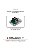
EA350
Generator Automatic Voltage Regulator
Operation Manual
Self Excited Automatic Voltage Regulator For General Generators
Compatible with Marathon SE350*
* Use for reference purpose only and not a genuine Marathon product.
EN61204-3 : 2001 certified
Headquarters : No.3, Lane 201, Chien Fu St., Chyan Jenn Dist., Kaohsiung, TAIWAN
Tel : + 886-7-8121771
Fax : + 886-7-8121775
URL : http://www.kutai.com.tw
1. SPECIFICATION
Power & Sensing Input
Voltage
85 ~ 135 VAC / 190 ~ 240 VAC
Frequency
50 / 60 Hz, Jumper selectable
External Volts Adjustment
± 5% with 1K ohm 1 watt trimmer
± 10% with 2K ohm 1 watt trimmer
Output
Voltage
EMI Suppression
Internal electromagnetic interference filtering
Current
Resistance
Max. 36 VDC @ 120 VAC input
Max. 73 VDC @ 240 VAC input
Continuous 4A
Intermittent 7A for 10 sec
(52 / 105VDC)
Min. 15 ohm Max. 100 ohm
Unit Power Dissipation
Max. 8 watt
Under Frequency Protection (Factory Setting)
60 Hz system presets knee point at 54 ~ 61 Hz
50 Hz system presets knee point at 45 ~ 51 Hz
Voltage Regulation
< ± 1% ( with 4% engine governing )
Dimensions
99.5mm L * 67mm W * 47.5mm H
Voltage Build-up
Residual voltage at AVR terminal > 5 VAC
Weight
205g ± 2%
Operating Temperature
- 40°C ~ 60°C
Certification
EN61204-3 : 2001 certified
* Test Report on request if required
Storage Temperature
- 65°C ~ 85°C
Burden
250 / 500VA Max.
11.4
99.5
90.4
10.0
59.7
11.4
41.9
24.1
67.0
.9
?4
58.7
16.3
47.5
UNIT : mm
Figure 1 Outline and Drilling Diagram
______________________________________________________________________________________
2
EA350
KUTAI ELECTRONIC
U/F
VOLTAGE REGULATOR
STAB
7 F- F+ 3
MODEL: EA350
6
VOLT
4
Rheostat
Jumper
J1
INPUT: 85-135Vac / 190-240Vac
50/60Hz, 500VA
OUTPUT: 36 Vdc / 73Vdc 3.5A
HZ HZ
60 50
Frequency
Jumper
Red
J2
OFF
ON
DIP SW
FUSE 4A/250V
Figure 2 Jumper and Potentiometer Control Locations
2. WIRING
2.1 Exciter Field Power Circuit
● Connect AVR terminal “F+” to field “+”, connect
AVR terminal “F–” to the field “–”.
● See Figure 5~6 for typical connection diagram.
When using a remote voltage adjust rheostat,
remove the jumper wire across terminals 6 and 7
and install a 2000 ohm 1/2 watt (minimum) rheostat.
This will give ±10% voltage variation from the
nominal. (For ±5% voltage variation use a 1000 ohm
1/2 watt rheostat). See Figure 5~6.
CAUTION !
2.4 Stability Adjustment
The exciter field dc resistance must be 15 ohms or
greater and less than 100 ohms.
● System stability is the ability of the generator to
respond to load transients. Decreasing the
stability makes the generator less sluggish and
faster to respond to toad transients. If the stability
of the regulator is decreased too much, the
generator will tend to hunt under steady state
If the exciter field dc resistance is less than 15 ohms
and the full load field current does not exceed the
maximum continuous current rating of the controller,
a resistor of sufficient wattage must be added in
series with the field to increase the total resistance
to 15 ohms.
2.2 Sensing / Power Input Circuit
Input power and sensing is achieved through
terminals 3 and 4. The voltage input requirement of
the EA350 is 120 to 240 VAC.
See Figure 5~6.
2.3 Voltage Adjustment
The screwdriver adjustable potentiometer adjusts
the generator output voltage. Adjustment clockwise
increases the generator output voltage.
● Conditions the screwdriver adjustable potentiometer
adjusts the system stability Adjustment clockwise.
● Increases the stability. Increasing the stability
increases the response time of the generator.
Conversely, decreasing the stability decreases
the response time of the generator.
2.5 V/Hz Roll-Off Frequency Selection
● The roll off point is the frequency where the
generator voltage starts to decrease. This
reduces the Kilowatt load to the engine, which
allows the engine to recover in speed transient
condition. Use jumper to select 50 Hz or 60 Hz.
The screwdriver adjustable potentiometer sets
the roll-off frequency from 54~61 Hz in the 60 Hz
setting or from 45~51 Hz in the 50 Hz setting.
______________________________________________________________________________________
EA350
3
● Set the voltage to the desired setting at rated
speed. Adjust engine speed to the desired roll-off
point. Turn the potentiometer counterclockwise
until the voltage starts to drop off. Then adjust the
potentiometer clockwise until the voltage returns
to rated voltage. Re-adjust engine speed to rated
speed.
GENERATOR OUTPUT(%FROM NORMINAL)
● The EA350 has the roll-off point preset to 58 Hz
in the 60 Hz mode and 48 Hz in the 50 Hz mode.
To change the roll-off point, adjust engine speed
to the desired rated speed. (50 or 60 Hz).
100
90
80
60
50
40
30
20
10
0
5
10
2.6 Corner Frequency Jumper
Regulator are delivered with the Corner Frequency
Jumper set for 60 hertz operation. This gives a
corner frequency of 55 hertz. For 50 hertz operation
and a corner frequency of 45 hertz, the Corner
Frequency Jumper must be moved to the 50 Hz
terminal.
2.7 Voltage Adjust Rheostat Jumper
● Rheostat Jumper connected across terminals 6
and 7. This enables adjustment of the generator
output voltage rheostat. A 1000 ohm, half-watt
rheostat
will
provide
adequate
voltage
adjustment range for most applications. Figure
5~6 shows the proper remote rheostat
connections.
● The EA350 potentiometer controls are accessible
through the controller front panel and are shown
in Figure 2.
2.8 Voltage Adjust Rheostat Jumper
2P DIP switch on for 120Vac generator system
2P DIP switch off for 240Vac generator system
2.9 Stability Selection
When excitation under voltage, it can result in
insufficient adjustment range for stability adjustment
and when excitation over voltage, the response from
the AVR becomes sluggish. The AVR is equipped
with 2 bridging wires J1 and J2 to help improve or
relief the condition. See Figure 2.
● If the unloaded excitation voltage is less than 7
VDC, please cut open the J2 red bridging wires.
● If the unloaded excitation voltage is greater
than25 VDC, please cut open the J1 white
bridging wires.
60HZ CURVE
50 HZ CURVE
70
15
20
25
30
35
40
45
50
55
60
65
70
FREQUENCY (HZ)
Figure 3
Frequency Compensation Curves
FREQUENCY COMPENATION (See Figure 1)
1. The frequency compensation characteristic of
Figure 1 used to improve system load pickup
performance by restraining voltage recovery
until frequency has also started to recover.
2. The regulator is shipped from the factory set
at a 45 Hz “corner frequency” for 50 Hz
systems. For 60 Hz systems, a 55 Hz corner
frequency is achieved by removing the
“50-50” external link.
3. OPERATION PROCEDURE
3.1 Operational Test
Complete the following steps before proceeding with
system start-up.
1. Connect the Analog Voltage Controller as shown
in the operational test diagram of Figure 8. Do not
apply power. Ensure that the light bulbs are rated
for 120 volts and less than 100 watts. Figure 4.
Operational Test Diagram.
2. Adjust the Regulator voltage adjust potentiometer
and remote voltage adjust rheostat (if used) fully
counterclockwise.
3. Apply 240 VAC, 60 Hz power to the controller.
The light bulbs should flash momentarily.
4. Slowly adjust the controller’s voltage adjust
potentiometer clockwise.
RESULT :
1. Before minimum luminance is reached, the light
bulbs should attain maximum luminance to
signify the regulation point.
2. At the regulation point, a small change in the
voltage adjust potentiometer or rheostat position
should turn the light bulbs on or off.
______________________________________________________________________________________
4
EA350
3.2 Preliminary Setup
Complete the following steps before proceeding with
system start-up.
● Verify that the Regulator specifications conform
with the requirements of the generator system.
● Ensure that the controller jumpers and dip sw are
installed/positioned as follows.
1. If a remote voltage-adjust rheostat will not be
used, ensure that the Voltage Adjust Rheostat
Jumper is connected across terminals 6 and 7.
2. If a 55 hertz corner frequency for a 60 hertz
system is desired, connect the Corner Frequency
Jumper to the 60 Hz terminal. If a 45 hertz corner
frequency for a 50 hertz system is desired,
connect the Corner Frequency Jumper to the 50
Hz terminal.
● Ensure that the connection between the
generator system and the Regulator are correct.
● Apply and remove the generator load to verify
stability If the generator responds too slowly or
hunts (oscillates):
● Check the generator output for excessive load or
a short circuit. Adjust the Regulator stability
control with no load applied.
● Check the stability of the governor system.
● Check regulation under normal
conditions. If the regulation is poor:
operating
1. Verify that the prime mover is operating at rated
speed.
2. Verify that the voltmeter is connected to the same
point as the Regulator sensing.
3. Use an average-sensing voltmeter (not an
rms-sensing voltmeter).
● Verify the corner frequency setting by slowly
reducing the generator frequency until the
generator output voltage just starts to decrease.
If adjustment of the corner frequency is required:
● Set the regulator voltage control potentiometer
fully counter-clockwise and the remote voltage
adjust rheostat (if used) to the centered position.
1. Rotate the under
counterclockwise.
● Adjust the regulator stability control potentiometer
fully clockwise. This provides the most stability
and the slowest response.
2. Reduce the generator frequency from nominal
(either 50Hz or 60Hz) to the desired corner
frequency.
● If user-adjustment of the under frequency control
potentiometer is required, start with the
potentiometer
adjusted
to
the
fully
counterclockwise position. Then, slowly adjust
the potentiometer clockwise to set.
3. Slowly adjust the under frequency control
clockwise until the generator output voltage just
starts to decrease.
3.3 System Start-Up
● Perform the steps under Preliminary Setup.
NOTE :
All AC voltage readings are to be taken with an
“ average ” reading voltmeter.
● Start Prime-mover and bring up to rated speed.
● Generator voltage should build up. If it does not
build up, perform the steps under Field Flashing.
● Slowly adjust the regulator voltage control
potentiometer (or remote voltage adjust rheostat)
until the generator voltage reaches the nominal
level. If the voltage does not build up to the rated
level :
frequency
control
fully
CAUTION :
All voltage readings are to be taken with an
average-reading
voltmeter
Meggers
and
high-potential test equipment must not be used. Use
of
such
equipment
could
damage
the
semiconductors contained in the controller.
4. FIELD FLASHING
When the regulator is operated with the generator
for the first time, the polarity of residual magnetism
may be reversed or too small to achieve the
necessary build-up voltage for the regulator. If
reversing the field connections does not induce
build-up, and the residual voltage is less than the
specified value of 5 VAC, shut down the
Prime-mover and proceed with the following steps :
1. With the Prime-mover at rest and the regulator’s
field output wires disconnected, apply a DC
source ( NOT grounded ) of no more than 6~12
Vdc with Positive to F+ and Negative to F-, in
2. If a minimal residual of 5 volts is not present,
series with a current-limiting resistor of 3~5 ohms
perform the steps under Field Flashing.
20 watt. (The set battery is a suitable source.)
______________________________________________________________________________________
1. Check the generator output for excessive load or
a short circuit.
EA350
5
2. Allow approximately 3 seconds before removing
the battery.
3. With the voltage regulator disconnected ( wires 3
and 4 ), start the prime mover and measure the
“ residual ” voltage available at the auxiliary
winding. If this voltage is greater than 5 VAC,
reconnect voltage regulator, and voltage build-up
should be successful. If less than 5 VAC is
measured, repeat field flashing procedure.
4. If residual voltage is greater than 5VAC, but AVR
still unable to build up voltage, please replace
with another AVR.
WARNING
Please make sure you have read and
understand the contents of the instruction
manual prior to installation. Incorrect wiring
connection may result in irreversible damage
to the product and other equipments.
This Automatic Voltage Regulator is not
equipped with loss-Sensing Protection
function / Over Excitation Protection. An
additional Over-Voltage Protection device for
load may be required to avoid possible
damage to the equipment or severe personal
injury or death.
EA350
EA350
Figure 4
Operational Test Diagram
Figure 5
EA350
EA350
Figure 6
3Ø 220VAC Diagram
1Ø 220VAC Diagram
Figure 7
3Ø 380VAC Diagram
______________________________________________________________________________________
6
EA350