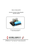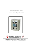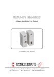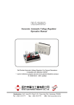
1
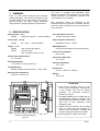
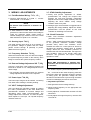
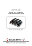
EA07
Generator Automatic Voltage Regulator
Operation Manual
Suitable for Single or Three Phase Self Excited Brushless Generator
Compatible replacement for Mecc Alte SR-7
* Not a genuine Mecc Alte product.
Headquarters : No.3, Lane 201, Chien Fu ST., Chyan Jenn Dist., Kaohsiung, TAIWAN
Tel : + 886-7-8121771
Fax : + 886-7-8121775
URL : http://www.kutai.com.tw
1. SUMMARY
EA07 is a self excited Analogue type Automatic
Voltage Regulator. The sensing and power inputs
are independent and accept power input from the
auxiliary winding. The wide voltage adjustment
range fulfills any voltage adjustment requirements.
The EA07 is equipped with adjustable under
frequency protection and adjustable over excitation
voltage protection for preventing generator from
over loading or over excitation.
Both protections status are indicated by two
individual LED when protection is activated. Also the
AVR has a built in EMI filter to prevent interference
to the generator.
2. SPECIFICATION
Sensing Input
Voltage
Power Input
Voltage
4A, 5
Range 90~350VAC
3A, 5C
80 ~ 270V
1 phase 50/60Hz
1 phase 50/60Hz
Output F+, F–
Voltage
Max. 63 VDC @ 220VAC
Current
Continuous 6A
Max. Intermittent 7A for 10 sec
Exciter Field DC Resistance
10 ~ 100 Ohm
Over Excitation Protection
40~Max VDC @ 0.3~20sec
Under Frequency Protection
Adjustable range 42 ~ 60 Hz
EMI Suppression
Internal electromagnetic interference filtering
Unit Power Dissipation
Max. 5 watt
Operating temperature
-40 ~ 65 °C
Voltage Regulation
< ±1% (with 4% engine governing)
Storage temperature
-40 ~ 80 °C
Voltage Build-up
Residual voltage at AVR terminal > 5 VAC, 25Hz
External Volts Adjustment
100K ohm 1/2 watt ± 7%
Dimensions
97mm L * 92mm W * 39mm H
Weight
275g ± 2%
ATTENTION
1. AVR can be mounted directly on the
engine, genset, switchgear, control panel,
or any position that will not affects
operation. For dimension reference,
please see Figure 1.
2. All voltage readings are to be taken with an
average-reading voltmeter Meggers and
high-potential test equipment must not be
used. Use of such equipment could
damage the AVR.
High Temperature
3. Secure all wiring connection. Do not install
AVR at a place with high vibrations to
prevent loose connections. For safety do
not touch the heat sink while in operation.
UNIT : mm
4. Fuse specification : 20mm 6.3A / 250V.
Outline and Drilling Diagram
Figure 1
______________________________________________________________________________________
2
EA07
3. WIRING / ADJUSTMENTS
3.7 STAB. Stability Adjustment
3.1 Field Excitation Wiring「
「3 F+, 1 F–」
● Slowly and precise adjustment of “STAB”
potentiometer can change the respond time
between the AVR and generator. Inadequate
adjustment will cause voltage instability and over
adjusting will cause sudden overly voltage
variation under heavy load.
● Connect AVR terminal “3” to field “+”, connect
AVR terminal “1” to the field “–”.
NOTE
The Exciter field resistance is between 10~
100 Ohm.
● If field resistance is less than 10 Ohm when
generator is under full load and the field voltage is
under the maximum output, please series a
suitable wattage (W) resistor to have the overall
field resistance to equal to 10~ 100 Ohm.
3.2 Sensing Input「
「4A, 5」
」
The rated sensing input range is 90 to 350VAC. If
the generator voltage is greater than the rated,
please connect through N (Neutral) to phase.
(Reference from Figure 2).
3.3 Frequency Selection「
「6, 5A」
」
When the terminals 6 & 5A on the AVR are bridged,
the system frequency is 60Hz. In the contrary, when
bridge is removed the system frequency is 50Hz.
3.4 External Voltage Adjustment VR「
「7, 5B」
」
Connect a 100K Ohm 1/2W voltage rheostat at VR
terminals to enable a ±7% voltage adjustment from
rated voltage.
* The terminals must be bridged when the external
voltage adjustment function is none required.
3.5 Power Input「
「3A, 5C」
」
The Power input range is 80 to 270VAC, connecting
from either main winding or auxiliary winding.
3.6 VOLT. Voltage Adjustment
User can adjust the generator voltage by rotating
the “VOLT” potentiometer on the AVR. Rotate the
potentiometer clockwise to increase voltage and
decreasing when rotate counterclockwise. The
voltage adjust rate is less than 1% when the power
factor equals to 1 to 0.8 (PF 1 to 0.8) and frequency
variation within 6%.
● Analogue type multi voltmeter is suggested when
adjusting the voltage stability. Adjust the “STAB”
potentiometer until the pointer on the multi
voltmeter is oscillating to its minimal.
3.8 Circuit Protection
● AMP. Over Excitation Protection Adjustment
(Overload protection).
Set the 「AMP」Overload protection value according
to the generator maximum excitation voltage
(40~Max VDC). When over excitation occurs
maintain the status for a short period of time then
decrease the generator voltage down to residual
voltage. When the Over excitation protection is
activated the O/E LED will illuminate, the higher the
over excitation value is the shorter delay time
becomes. The generator will require stopping
operation to reset.
NOTE
When AMP potentiometer is adjusted fully
clockwise, the Over Excitation protection will
be disabled.
● Hz. Under Frequency Protection Adjustment
「Hz.」Is used to set the under frequency protection
knee point. When the generator frequency declines
to setting point, the generator voltage will also
decrease in the same time to prevent high excitation
current from damaging the AVR or the exciter.
● Adjustment procedure
1. Start generator and let voltage build up.
2. Adjust engine frequency to the appropriate low
frequency value.
3. Slowly adjust Hz. Potentiometer until the U/F LED
illuminates.
4. Finally adjust the engine frequency until the LED
is turned off.
______________________________________________________________________________________
EA07
3
4. OPERATION PROCEDURE
4.1 Please confirm the follow condition
before starting the generator :
● Starting Setting
1. Confirm if the AVR specification conforms to the
system requirements ?
2. Confirm the AVR wiring ?
3. Confirm correct frequency selected ?
4. Confirm the generator rated voltage with the AVR
sensing input ?
6. The voltage adjustable range should be ±1%
under no load or full load. If the adjustable range
in not within such range, please check the below :
● Generator under frequency (Lower than low
frequency protection knee point).
● Severely deformed generator output wave
form.
● Capacitive load over ratio (Power factor in
lead).
● Change the AVR and restart.
● Under over excitation voltage protection
(Overload protection).
5. Adjust “VOLT” potentiometer fully counterclockwise?
Adjust “STAB” potentiometer to the center position?
Adjust “AMP” potentiometer fully clockwise?
4.2 Starting Generator
1. Reconfirm all setting and wiring.
4.3 Field Flashing
When the regulator is operated with the generator
for the first time, the polarity residual magnetism
may not correct or the magnitude not enough. If the
generator does not build-up after startup, shut down
the prime mover and proceed with the following
steps :
ATTENTION
The AVR reading AC voltage are all average
value.
2. Start generator and adjust to rated frequency.
The first measured voltage value should be under
the rated voltage. If not, then reconfirm the start
setting.
3. Slowly adjust “VOLT” potentiometer to the rated
voltage, at this time the generator voltage may
become unstable. Adjust the “STAB.” potentiometer
anticlockwise, until the oscillation stabilizes. Over
adjustment may cause short oscillation when
load applied or load type varies.
SUGGESTION
Adjust the “STAB.” potentiometer to the
point where the oscillation occurs and then
adjust the potentiometer counterclockwise
by 1/6 of rotation.
4. If voltage can not be adjusted or to the rated
value, please check to see if the generator
frequency is too slow (Under frequency
protection activated). If residual voltage is below
5VAC, then please execute field flashing to help
build up the residual voltage.
5. Make sure the generator and AVR are both under
normal operation conditions.
1. Stop generator operation, disconnect AVR + and –
wirings then apply a DC source (Not grounded) of
not more than 12VDC, to generator F+ (Positive)
and F– (Negative) in series with a limiting resistor
of 3 to 5 ohms 20 watt.
2. Allow approximately 3 seconds before removing
the dc source.
3. Start generator and measure residual voltage at
generator leads 3A, 5C. If measured voltage is
greater then 5VAC please carefully reconnect all
AVR wirings. Please repeat field flashing
procedure if less than 5VAC residual voltage is
measured.
4. If residual voltage is greater than 5VAC, but AVR
still unable to build up voltage, please replace
with another AVR.
WARNING
Overly field flashing may damage the AVR or
generator excitation winding.
4.4 Maintenance
Regular maintenance to make sure the AVR surface
is clean and free from oil or moisture. All connection
terminals and wirings must be firmly tightened and
no signs of visible oxidation or erosion.
______________________________________________________________________________________
4
EA07
F+
F-
O/E U/F
EXCITER
EA07
AMP. HZ. STAB VOLT
High Temperature
10
9
12
8
5
7
OUT
6
4
2
IN
STATOR
11
3
1
Figure 2
Diagram
※ Use only original supplied spare protection fuse for fuse replacement.
※ Please accept our sincere apology if any modification in performance, specification or appearance is
made without prior notice.
______________________________________________________________________________________
EA07
5