1
UEIPAC SDK User Manual
UEIPAC Software Development Kit
User Manual 1.2
February 2007 Edition
© Copyright 2007 United Electronic Industries, Inc. All rights reserved
No part of this publication may be reproduced, stored in a retrieval system, or transmitted, in any form by any means,
electronic, mechanical, by photocopying, recording, or otherwise without prior written permission.
1
UEIPAC SDK User Manual
Table of contents
1. Introduction............................................................................................ 3
2. Setting up a development system.......................................................... 5
2.1.
2.2.
2.3.
2.4.
Windows Host..................................................................................................... 5
Linux Host .......................................................................................................... 5
Installation........................................................................................................... 6
SDK directory layout .......................................................................................... 6
3. Connecting to the PowerDNA IO module ........................................... 7
3.1.
3.2.
3.3.
3.4.
3.5.
Connecting through the serial port...................................................................... 7
Root file system .................................................................................................. 9
Configuring the IP address................................................................................ 10
Connecting through Telnet ............................................................................... 10
Changing the password ..................................................................................... 10
4. Transferring files ................................................................................. 11
4.1.
4.2.
4.3.
FTP Client......................................................................................................... 11
FTP Server ........................................................................................................ 11
TFTP Client ...................................................................................................... 11
5. Testing the I/O layers........................................................................... 12
5.1.
5.2.
5.3.
Devtbl................................................................................................................ 12
Run examples.................................................................................................... 12
PowerDNA server............................................................................................. 13
6. Application development..................................................................... 14
6.1.
Prerequisites...................................................................................................... 14
6.2.
Compiling and running Hello World ................................................................ 14
6.3.
Debugging Hello World.................................................................................... 15
6.4.
PowerDNA Library........................................................................................... 16
6.4.1.
Building and running the examples .......................................................... 17
6.4.2.
PowerDNA API ........................................................................................ 18
6.4.2.1.
RTDMAP API .................................................................................. 18
6.4.2.2.
Event API.......................................................................................... 19
7. Firmware installation and upgrade.................................................... 20
7.1.
7.2.
7.3.
Installing or upgrading the Linux kernel .......................................................... 20
Initializing an SD card ...................................................................................... 20
Installing the standard DAQBios firmware ...................................................... 21
2
UEIPAC SDK User Manual
1. Introduction
The UEIPAC SDK extends the capability of the PowerDNA distributed data acquisition
system. With the UEIPAC SDK, you can create programs that will execute directly on
the PowerDNA IO module. You can create standalone applications that don’t require any
host PC to control and monitor your PowerDNA hardware.
A Linux kernel replaces the standard “DAQBIOS” firmware in PowerDNA’s flash
memory and uses a SD-Card as its local file system. This file system contains the other
components of the operating system such as libraries, utilities, init script and daemons.
After power-up, you have a ready-to-go Linux operating system with FTP and web
servers as well as a command line shell accessible from either the serial port or telnet and
SSH over the network.
You can also configure the PowerDNA IO module to execute your application after
booting-up.
Your application runs as a regular Linux process giving you access to the standard
POSIX API provided by the GNU C runtime library (glibc) as well as any other library
that can be compiled for Linux (for example: libxml, libaudiofile…).
The UEIPAC SDK comes with a library dedicated to communicate with the PowerDNA
I/O layers.
It provides the same API as the hosted PowerDNA library; allowing you to reuse existing
programs that were designed to run on a host PC and communicate with PowerDNA over
the network.
You can port those programs to run directly on the PowerDNA IO module with few
modifications.
3
UEIPAC SDK User Manual
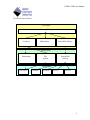
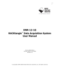
User Space
User Application
C Library
Other library…
PowerDNA Library
Kernel Space
File
System
Networking
PowerDNA
Drivers
Hardware
CPU layer
AI layer
AO layer
DIO layer
Other layer
4
UEIPAC SDK User Manual
2. Setting up a development system
A development system is composed of the software tools necessary to create an
embedded application targeting Linux on a PowerPC processor.
The development tools can run on a Linux PC or on a Windows PC using the Cygwin
environment.
It contains the following:
• GCC cross-compiler targeting the PowerDNA IO module PPC processor.
• GNU toolchain tools such as make.
• Standard Linux libraries such as glibc.
• PowerDNA library to access the various PowerDNA data acquisition devices
2.1.
Windows Host
If you don’t have Cygwin already installed, download and run the installer “setup.exe”
from http://www.cygwin.com.
Running setup.exe will install or update Cygwin. We need the packages from the
following categories:
• Archive: tools to create and read archives files such as zip, bx2 and tar.
• Admin: administration tools and disk utilities.
• Devel: Development tools such as make and gcc.
• Net: Network utilities such as ftp, tftp and telnet.
Insert the “UEIPAC SDK” CDROM in your CD drive. Then open a cygwin command
line shell.
Go to the CD’s root directory (the example below assumes that the CD-ROM is the D:
drive):
cd /cygdrive/d
2.2.
Linux Host
Insert the “UEIPAC SDK” CDROM in your CD drive. You might need to mount it if
your Linux distribution doesn’t detect the CDROM automatically.
To mount it, type:
mount /dev/cdrom /mnt/cdrom
cd /mnt/cdrom
5
UEIPAC SDK User Manual
2.3.
Installation
Run the installation script:
./install.sh
The script will ask where you want to install the SDK.
The default installation directory is <HOME>/uei/UEIPAC-SDK-<version>. You can
override this setting with any directory of your choice.
2.4.
•
•
•
•
•
SDK directory layout
powerpc-604-linux-gnu: the GCC cross compiler
doc: the manuals in PDF and HTML format
kernel: the kernel source code and binary image
root_fs: the root file system installed on the SD card
sdk: the powerdna software development kit
6
UEIPAC SDK User Manual
3. Connecting to the PowerDNA IO module
Your PowerDNA IO module must be pre-configured to run Linux:
• A Linux kernel is loaded in flash memory.
• An SD card containing the root file system is inserted.
If you have a PowerDNA module with the standard “DAQBIOS” firmware, contact UEI
to install Linux.
3.1.
Connecting through the serial port
Connect the serial cable to the serial port on the PowerDNA cube and the serial port on
your PC.
You will need a serial communication program:
• Windows: ucon, MTTTY or HyperTerminal.
• Linux: minicom or cu (part of the uucp package).
The PowerDNA I/O module uses the serial port settings: 57600 bits/s, 8 data bits, 1 stop
bit and no parity.
Run your serial terminal program and configure the serial communication settings
accordingly.
Connect the DC output of the power supply (24VDC) to the “Power In” connector on the
PowerDNA cube and connect the AC input on the power supply to an AC power source.
You should see the following message on your screen:
U-Boot 1.1.4 (Jan 10 2006 - 19:20:03)
CPU:
MPC5200 v1.2 at 396 MHz
Bus 132 MHz, IPB 66 MHz, PCI 33 MHz
Board: UEI PowerDNA MPC5200 Layer
I2C:
85 kHz, ready
DRAM: 128 MB
Reserving 349k for U-Boot at: 07fa8000
FLASH: 4 MB
In:
serial
Out:
serial
Err:
serial
Net:
FEC ETHERNET
Type "run flash_nfs" to mount root filesystem over NFS
7
UEIPAC SDK User Manual
Hit any key to stop autoboot:
5
This message is coming from the cube’s boot loader U-Boot. It waits 5 seconds to give
the user a chance to alter its configuration, if necessary.
After the count-down ends, U-Boot loads the Linux kernel from flash, uncompresses it,
and starts it:
## Booting image at ffc10000 ...
Image Name:
Linux-2.6.16.1
Created:
2006-11-10 16:07:06 UTC
Image Type:
PowerPC Linux Kernel Image (gzip compressed)
Data Size:
917636 Bytes = 896.1 kB
Load Address: 00000000
Entry Point: 00000000
Verifying Checksum ... OK
Uncompressing Kernel Image ... OK
id mach(): done
MMU:enter
MMU:hw init
MMU:mapin
MMU:setio
MMU:exit
setup_arch: enter
setup_arch: bootmem
arch: exit
Linux version 2.6.16.1 (frederic@ubuntu) (gcc version 4.0.2) #1
PREEMPT Fri Nov 10 11:07:01 EST 2006
Built 1 zonelists
Kernel command line: console=ttyPSC0,57600 root=62:1 rw
PID hash table entries: 1024 (order: 10, 16384 bytes)
Console: colour dummy device 80x25
Dentry cache hash table entries: 32768 (order: 5, 131072 bytes)
Inode-cache hash table entries: 16384 (order: 4, 65536 bytes)
Memory: 127744k available (1476k kernel code, 476k data, 88k init, 0k
highmem)
Mount-cache hash table entries: 512
NET: Registered protocol family 16
DMA: MPC52xx BestComm driver
MPC52xx BestComm inited
io scheduler noop registered
io scheduler anticipatory registered (default)
io scheduler deadline registered
io scheduler cfq registered
Serial: MPC52xx PSC driver
ttyPSC0 at MMIO 0xf0002000 (irq = 40) is a MPC52xx PSC
RAMDISK driver initialized: 16 RAM disks of 6144K size 1024 blocksize
fec_mii_init: Dummy function
Bitrate set to 4125
8
UEIPAC SDK User Manual
ExecCmdInit, r=0xc1
ExecCmdInit, r=0x1
mice: PS/2 mouse device common for all mice
NET: Registered protocol family 2
IP route cache hash table entries: 2048 (order: 1, 8192 bytes)
TCP established hash table entries: 8192 (order: 3, 32768 bytes)
TCP bind hash table entries: 8192 (order: 3, 32768 bytes)
TCP: Hash tables configured (established 8192 bind 8192)
TCP reno registered
TCP bic registered
NET: Registered protocol family 1
NET: Registered protocol family 17
VFS: Mounted root (ext2 filesystem).
Freeing unused kernel memory: 88k init
BusyBox v1.2.2 (2006.11.03-19:16+0000) Built-in shell (ash)
Enter 'help' for a list of built-in commands.
~ #
You can now navigate the file system and enter standard Linux commands such as ls, ps,
cd…
3.2.
Root file system
The root file system is entirely located on the SD card. It uses the EXT2 format.
It is recommended you type the command “halt” before powering down the IO module
and the command “reboot” to restart the IO module.
If you power down the IO module abruptly, the following message will appear at boot
time:
EXT2-fs warning: mounting unchecked fs, running e2fsck is recommended
You must check the file system for errors with the following commands:
# mount -o remount,ro /
# e2fsck /dev/sdcard1
e2fsck 1.38 (30-Jun-2005)
/dev/sdcard: clean, 702/124160 files, 6632/247872 blocks
# reboot
9
UEIPAC SDK User Manual
3.3.
Configuring the IP address
Your PowerDNA cube is configured at the factory with the IP address 192.168.100.2 to
be part of a private network.
You can change the IP address for the current session using the command:
ifconfig eth0 <new IP address>
To make the change permanent, edit the file /etc/rc.sh and change the line that calls
ifconfig.
3.4.
Connecting through Telnet
Once the IP address is configured, you shouldn’t need the serial port anymore. You can
use telnet to access the exact same command line interface.
Type the following command on your host PC, then login as “root”. The password is
“root”.
telnet <Cube’s IP address>
Type the command “exit” to logout.
3.5.
Changing the password
Type the following command and enter your new password two times:
passwd
You can now logout and login with your new password.
10
UEIPAC SDK User Manual
4. Transferring files
You can use either FTP or TFTP to transfer files between your host PC and the
PowerDNA IO module.
4.1.
FTP Client
To connect to an external FTP server from the PowerDNA IO module, use the commands
“ftpput” and “ftpget”.
To retrieve a file from an FTP server:
ftpget –u <username> -p <password> <FTP server IP address> <local
file name> <remote file name>
To send a file to an FTP server:
ftpput –u <username> -p <password> <FTP server IP address> <remote
file name> <local file name>
4.2.
FTP Server
The UEIPAC SDK comes with the vsftpd FTP server. The server is not active by default.
You can start it using the following command:
/usr/sbin/vsftpd &
Add this command to the file rc.sh to start the server automatically when the PowerDNA
IO module boots up.
4.3.
TFTP Client
To retrieve a file from a TFTP server, use the following command:
tftp –g –r <remote file name> <TFTP server IP address>
11
UEIPAC SDK User Manual
5. Testing the I/O layers
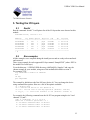
5.1.
Devtbl
Run the command “devtbl.” It will print a list of the I/O layers that were detected on this
module.
PowerDNA Driver, version 1.0.0
Address
Irq Model Option Phy/Virt S/N
Pri LogicVer
------------------------------------------------------------0xc9080000
7
207
1
phys
0027887
0 02.0c.05
0xc9090000
7
403
1
phys
0030384
0 02.0c.05
0xc90a0000
7
403
1
phys
0030385
0 02.0c.05
0xc90b0000
7
501
1
phys
0029693
0 02.0c.05
0xc90c0000
7
601
1
phys
0030279
0 02.0c.05
------------------------------------------------------------~ #
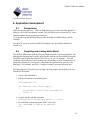
5.2.
Run examples
All the examples were compiled during the install process and are ready to be transferred
and executed.
There is one example for each supported I/O layer named “SampleXXX” (where XXX is
the model ID of each layer).
Go to the directory “<UEIPAC SDK directory>/sdk/DAQLib_Samples” and copy the
chosen example to your module, using one of the methods described in section 4.
For example, FTP:
ftp <PowerDNA IO module IP address>
bin
cd tmp
put SampleXXX
The example by default uses the first I/O layer (device 0). You can change the device
using command line options. Here are a few of the options available:
-h
-d
-f
-c
: display help
n: selects the device to use (default: 0)
n.nn : set the rate of the DAQ operation (default: 1000 Hz)
"x,y,z,..." : select the channels to use (default: channel 0)
For example, the following command runs the AI-207 test program using device 2 and
channels 3,5,and 7:
/tmp # ./Sample207 -d 2 -c "3,5,7"
There are 3 channels specified: 3 5 7
0: ch3 bdata 310dfff6 fdata 15.781501V
0: ch5 bdata 310dfff7 fdata 15.781501V
0: ch7 bdata 310dfff6 fdata 15.781501V
12
UEIPAC SDK User Manual
1: ch3 bdata 310dfff6 fdata 15.781501V
1: ch5 bdata 310dfff6 fdata 15.781501V
1: ch7 bdata 310dfff6 fdata 15.781501V
...
5.3.
PowerDNA server
PowerDNA server emulates the behavior of a PowerDNA IO module running the
standard DAQBIOS firmware. It emulates a subset of the DAQBIOS protocol so that the
PowerDNA IO module can be accessed from PowerDNA Explorer or the UeiDaq
framework in immediate mode. ACB and DMAP modes are not supported in the
PowerDNA server.
To run the PowerDNA server, type the command “pdnaserver &”.
13
UEIPAC SDK User Manual
6. Application development
6.1.
Prerequisites
Make sure that the directory “<UEIPAC SDK directory>/powerpc-604-linux-gnu/bin” is
added to your PATH environment variable. This will allow you to invoke the GCC cross
compiler without having to specify its full path.
It is required to run the different Makefiles that build the PowerDNA library and the
examples.
Start the FTP server on your PowerDNA IO module if it is not already running (see
section 4.2).
6.2.
Compiling and running Hello World
The UEIPAC SDK comes with the GNU toolchain compiled to run on your host PC and
build binaries targeting the PowerPC processor that runs on your PowerDNA IO module.
The SDK comes with all the familiar GNU tools: ar, as, gcc, ld, objdump… To avoid
confusion with a different version of those tools (for example a version compiled to run
and produce binaries for your host PC), their names are prefixed with “powerpc-604linux-gnu-“. For example, the GNU C compiler is named “powerpc-604-linux-gnu”.
The following steps will guide you in writing your first program and running it on your
PowerDNA IO module.
1. Create a file called hello.c
2. Edit the file and enter the following text:
#include<stdio.h>
int main(int argc, char* argv[])
{
printf(“Hello World from PowerDNA\n”);
return 0;
}
3. Compile the file with the command:
powerpc-604-linux-gnu-gcc hello.c –o hello
4. Download the compiled program “hello” to the cube:
ftp <PowerDNA IO module IP address>
bin
14
UEIPAC SDK User Manual
cd tmp
put hello
5. Login on your PowerDNA IO module using either Telnet or the serial console and
type the following commands:
cd /tmp
chmod +x hello
./hello
You should see the text “Hello World from PowerDNA” printed on the console.
6.3.
Debugging Hello World
The UEIPAC SDK contains a version of the GNU debugger compiled to run on your host
PC and debug binaries targeting the PowerPC processor. Its name is “powerpc-604-linuxgnu-gdb”.
It allows you to debug a program remotely from your host PC.
The following steps will guide you in debugging the “hello world” program.
1. Rebuild the hello program using the –g option. This will include debug symbols
in the binary file.
powerpc-604-linux-gnu-gcc –g hello.c –o hello
2. Upload the new binary to the PowerDNA IO module using FTP.
3. On the PowerDNA console, start the GDB server to debug the program remotely
(It will communicate with the host on port 1234):
gdbserver :1234 hello
4. On the host, start GDB and connect to the target.
powerpc-604-linux-gnu-gdb hello
target remote <PowerDNA IP address>:1234
5. Set the shared library search path so that GDB will find the proper library used by
your program:
set solib-search-path <PowerDNA Driver Dir>/powerpc-604-linuxgnu/powerpc-604-linux-gnu/lib<PowerDNA Driver Dir>/sdk/DAQLib
Note that this step is only necessary if you wish to step inside the code of the
shared libraries. If you don’t set this variable, GDB will print a few error
messages about library mismatch, but you can still go ahead and debug your
program.
15
UEIPAC SDK User Manual
6. The program is now in “running” state and GDB paused its execution. Let’s put a
breakpoint at the beginning of the “main” function:
break main
7. We can now resume execution with the “cont” command and GDB will pause the
execution again when entering the “main” function.
8. You can step in your program using the “n” command to step over each line of
execution and “s” to step inside any called functions.
To avoid typing the same commands over and over when starting a debugging session,
you can create a file named “.gdbinit” in your home directory. This file will contain
commands that you want GDB to execute at the beginning of a session.
For example, the following “.gdbinit” file automatically connects to the target and pauses
execution in the main function each time you start gdb:
set solib-search-path <PowerDNA Driver Dir>powerpc-604-linuxgnu/powerpc-604-linux-gnu/lib<PowerDNA Driver Dir>/sdk/DAQLib
target remote 192.168.100.2:1234
break main
cont
Read the GDB documentation at http://sourceware.org/gdb/documentation/ to learn how
to fully use the GDB debugger.
6.4.
PowerDNA Library
The PowerDNA library implements the API used to program the PowerDNA IO layers:
The following layers are supported by the UEIPAC SDK:
• Analog Input: AI-201, AI-205, AI-207, AI-208, AI-225
• Analog Output: AO-302, AO-308
• Digital Input/Output: DIO-401, DIO-402, DIO-403, DIO-404, DIO-405, DIO-406
• Counter/Timer: CT-601
• Messaging: SL-501, CAN-503
The source code is installed in “<UEIPAC SDK directory>/sdk/DAQLib”.
Examples are located in “<UEIPAC SDK directory>/sdk/DAQLib_Samples”.
The UEIPAC SDK uses the exact same API as the PowerDNA Software Suite. It even
allows you to control other IO modules that run the standard DAQBios firmware from the
16
UEIPAC SDK User Manual
IO module running Linux the same way you would from a host PC running Windows or
Linux.
The PowerDNA API uses the IP address specified in the function DqOpenIOM() to
determine whether you wish to access the layers local to the IO module or “remote”
layers installed in another IO module. Set the IP address to the loopback address
“127.0.0.1” and the API will know that you want to access the “local” layers.
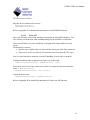
The UEIPAC SDK only supports the immediate (also known as “point by point”) and
DMAP modes to control the “local” layers. You can, however, use all the other modes
(ACB, M3) to control “remote” layers installed in I/O modules that run the DAQBios
firmware over the network.
Immediate
ACB
DMAP
M3
DAQBios
Yes
Yes
Yes
Yes
Firmware running on the IO module
Linux/local layers
Linux/remote layers
Yes
Yes
No
Yes
Yes
Yes
No
Yes
6.4.1. Building and running the examples
Change your current directory to “<UEIPAC SDK directory>/sdk/DAQLib_Samples”
and type make to make sure that your setup can build the samples correctly.
If you get any errors while building the examples, check that the path to the crosscompiler is in your PATH environment variable and that the environment variable
PDNAROOT is set to the SDK directory.
You can now transfer any of the built examples to the IO module, using FTP, and run
them.
Each example accepts command line options to specify the following parameters:
• -d <device id>: specify the device
• -c <channel list>: specify the channel list
• -f <frequency>: specify the rate
• -n <number of Scans>: specify the number of samples per channels
For example, the following command runs the Sample201example to acquire channels
0,2 and 4 from device 1:
Sample201 –d 1 –c “0,2,4”
17
UEIPAC SDK User Manual
6.4.2. PowerDNA API
The following sections detail the most commonly used APIs when running your program
on PowerDNA hardware.
Refer to the “PowerDNA API Reference Manual” document to learn more about the
other APIs dedicated to communicate with PowerDNA hardware over Ethernet.
6.4.2.1.
RTDMAP API
DMAP is one of the operation modes of PowerDNA. It continuously refreshes a set of
channels that can span multiple layers at a specified rate paced by PowerDNA's hardware
clock.
Values read from or written to each configured channel are stored in an area of memory
called the DMAP. At each clock tick, the firmware synchronizes the DMAP values with
their associated physical channels.
Here is a quick tutorial on using the RTDMAP API (handling of error codes is omitted):
Initialize the DMAP to refresh at 1000 Hz:
DqRtDmapInit(handle, 1000.0);
Add channel 0 from the first input subsystem of device 1:
chentry = 0;
DqRtDmapAddChannel(handle, 1, DQ_SS0IN, &chentry, 1);
Add channel 1 from the first output subsystem of device 3:
chentry = 1;
DqRtDmapAddChannel(handle, 3, DQ_SS0OUT, &chentry, 1);
Start all devices that have channels configured in the DMAP:
DqRtDmapStart(handle);
Update the value(s) to output to device 3:
outdata[0] = 5.0;
DqRtDmapWriteScaledData(handle, 3, outdata, 1);
Synchronize the DMAP with all devices:
DqRtDmapRefresh(handle);
Retrieve the data acquired by device 1:
DqRtDmapReadScaledData(handle, 1, indata, 1);
18
UEIPAC SDK User Manual
Stop the devices and free all resources:
DqRtDmapStop(handle);
DqRtDmapClose(handle);
Refer to Appendix A for detailed documentation of each RTDMAP function.
6.4.2.2.
Event API
The event API only works when running your program on PowerDNA hardware. You
can’t call any event function when communicating with PowerDNA over Ethernet.
The event API allows you to be notified in your application when a hardware event
occurs.
The hardware events are:
• SyncIn event: a digital edge was sensed on the syncin pin of the Sync connector.
• Timer event: occurs at each tick of a hardware timer located on the CPU layer.
Here is a quick tutorial on using the event API (handling of error codes is omitted):
Configure hardware timer to generate an event every millisecond.
DqEmbConfigureEvent(handle, DqEmbEventTimer, 1000);
Wait for the next event. If no event occurs or after 2 seconds, the function returns the
event “DqEmbEventTimeout”:
DqEmbWaitForEvent(handle, 2000, &event);
Cancel the timer event:
DqEmbCancelEvent(handle, DqEmbEventTimer);
Refer to Appendix B for detailed documentation of each event API function.
19
UEIPAC SDK User Manual
7. Firmware installation and upgrade
7.1.
Installing or upgrading the Linux kernel
Your PowerDNA IO module comes with the Linux kernel already installed into flash
memory.
It is possible to update that Linux kernel, if needed.
You first need to install a TFTP server on your host PC and copy the new kernel image
received from UEI technical support in the TFTP server’s directory. Kernel image files
are usually named uImage-2.6.x.x.
Connect to the IO module through the serial port and power-up the cube. Press a key
before the 5 second countdown ends to enter U-Boot’s command line interface.
1. Erase unprotected part of flash memory:
erase all
2. Configure U-Boot to use your host PC as TFTP server:
setenv server_ip <IP address of your host PC>
saveenv
3. Download the new kernel from the TFTP server.
tftp 200000 uImage
4. Write kernel into flash.
cp.b 200000 FFC10000 ${filesize}
5. Boot the new kernel:
bootm ffc10000
7.2.
Initializing an SD card
Your PowerDNA IO module came pre-installed with an SD card containing the root file
system necessary to run Linux.
You might want to initialize a new SD card if the factory-installed card becomes
unusable or you decide to upgrade to a faster or bigger one.
Note: You need to run Linux on your host PC to initialize an SD card. This is required
because the SD card must be formatted with the ext2 file system. To do this:
1. Insert the SD card in a USB adapter connected to your host PC.
20
UEIPAC SDK User Manual
2. Find out the name of the device node associated with the card. Type the command
“dmesg” and look for a message at the end of the log similar to:
SCSI: device sda: 1984000 512-byte hdwr sectors (1016
MB)
This message tells us that the device node we are looking for is “/dev/sda”.
3. Erase all partitions from the SD card and create one primary partition using all the
space available on the card:
fdisk /dev/sda
Command (m for help): d
Selected partition 1
Command (m for help): n
Command action
e extended
p primary partition (1-4)
p
Partition number (1-4):1
First Cylinder (1-1016, default 1):1
Last Cylinder … (1-1016, default 1016):1016
Command (m for help): w
4. The device node associated with the partition we just created is “/dev/sda1”. Let’s
format this new partition:
mke2fs /dev/sda1
5. Mount the new partition and copy the root file system from the SDK directory:
mount /dev/sda1 /mnt
cp –rd < UEIPAC SDK directory>/root_fs/* /mnt
6. Unmount the SD card and insert it in the PowerDNA I/O module. It is now ready
to boot.
7.3.
Installing the standard DAQBios firmware
You can replace the Linux kernel with the DAQBios firmware if you want to ontrol your
PowerDNA IO module from a PC or another IO module running Linux.
Connect to the IO module through the serial port and power-up the cube. Press a key
before the 5 second countdown ends to enter U-Boot’s command line interface.
1. Erase unprotected part of flash memory:
erase all
21
UEIPAC SDK User Manual
2. Upload the new firmware from the serial port, using the following command:
loads
3. Start transferring the DAQBios firmware (romimage_X_X_X_X.mot) as a text
file from your serial terminal program.
4. Set U-Boot’s boot command to start the firmware automatically:
setenv bootcmd fwjmp
saveenv
5. Boot the new firmware:
fwjmp
22
UEIPAC SDK User Manual
Appendix A: RTMAP API
DqRtDmapInit
Syntax:
int DqRtDmapInit(int handle, double refreshRate);
Input:
int handle
Handle to the IOM
double refreshRate
Rate at which the IOM will refresh its version of the
DMAP.
Return:
DQ_ILLEGAL_HANDLE invalid IOM handle
DQ_NO_MEMORY
memory allocation error or exceeded maximum
table size
DQ_SUCCESS
command processed successfully
Description:
Initialize the specified IOM to operate in DMAP mode at the specified refresh
rate.
DqRtDmapAddChannel
Syntax:
int DqRtDmapAddChannel(int handle, int dev, int
subsystem, uint32* cl, int clSize);
Input:
int handle
Handle to the IOM
int dev
ID of the device where the channels are located
int subsystem
The subsystem to use on the device (ex:DQ_SS0IN)
uint32* cl
Array containing the channels to add to the DMAP
int clSize
Size of the channel array
Return:
DQ_ILLEGAL_HANDLE invalid IOM handle
DQ_BAD_DEVN
there is no device with the specified number
DQ_BAD_PARAMETER the subsystem is invalid for this device
DQ_SUCCESS
command processed successfully
Description:
Add one or more channels to the DMAP.
23
UEIPAC SDK User Manual
DqRtDmapGetInputMap
Syntax:
int DqRtDmapGetInputMap(int handle, int dev, unsigned
char** mappedData);
Input:
int handle
Handle to the IOM
int dev
ID of the device where the channels are located
Output:
mappedData
pointer to the beginning of the device's input DMAP
buffer
Return:
DQ_ILLEGAL_HANDLE invalid IOM handle
DQ_BAD_DEVN
there is no device with the specified number
DQ_SUCCESS
command processed successfully
Description:
Get pointer to the beginning of the input data map allocated for the specified
device.
DqRtDmapGetInputMapSize
Syntax:
int DqRtDmapGetInputMapSize(int handle, int dev, int*
mapSize);
Input:
int handle
Handle to the IOM
int dev
ID of the device where the channels are located
Output:
mappedSize
size in bytes of the device's input data map.
Return:
DQ_ILLEGAL_HANDLE invalid IOM handle
DQ_BAD_DEVN
there is no device with the specified number
DQ_SUCCESS
command processed successfully
Description:
Get the size in bytes of the input map allocated for the specified device.
24
UEIPAC SDK User Manual
DqRtDmapGetOutputMap
Syntax:
int DqRtDmapGetOutputMap(int handle, int dev, unsigned
char** mappedData);
Input:
int handle
Handle to the IOM
int dev
ID of the device where the channels are located
Output:
mappedData
pointer to the beginning of the device's output
DMAP buffer
Return:
DQ_ILLEGAL_HANDLE invalid IOM handle
DQ_BAD_DEVN
there is no device with the specified number
DQ_SUCCESS
command processed successfully
Description:
Get pointer to the beginning of the output data map allocated for the specified
device.
DqRtDmapGetOutputMapSize
Syntax:
int DqRtDmapGetOutputMapSize(int handle, int dev, int*
mapSize);
Input:
int handle
Handle to the IOM
int dev
ID of the device where the channels are located
Output:
mappedSize
size in bytes of the device's output data map.
Return:
DQ_ILLEGAL_HANDLE invalid IOM handle
DQ_BAD_DEVN
there is no device with the specified number
DQ_SUCCESS
command processed successfully
Description:
Get the size in bytes of the output map allocated for the specified device.
25
UEIPAC SDK User Manual
DqRtDmapReadScaledData
Syntax:
int DqRtDmapReadScaledData(int handle, int dev,
double* scaledBuffer, int bufferSize);
Input:
int handle
Handle to the IOM
int dev
ID of the device where the channels are located
int bufferSize
Size of the scaledBuffer in bytes
Output:
double*scaledBuffer
The buffer containing the scaled data.
Return:
DQ_ILLEGAL_HANDLE invalid IOM handle
DQ_BAD_DEVN
there is no device with the specified number
DQ_SUCCESS
command processed successfully
Description:
Read and scale data stored in the input map for the specified device.
Note:
The data read is the data transferred by the last call to DqRtDmapRefresh().
This function should only be used with devices that acquire analog data such as
the AI-2xx series.
DqRtDmapReadRawData16
Syntax:
int DqRtDmapReadRawData16(int handle, int dev,
unsigned short* rawBuffer, int bufferSize);
Input:
int handle
Handle to the IOM
int dev
ID of the device where the channels are located
int bufferSize
Size of the scaledBuffer in bytes
Output:
unsigned short*rawBuffer
The buffer containing the raw data.
Return:
DQ_ILLEGAL_HANDLE invalid IOM handle
DQ_BAD_DEVN
there is no device with the specified number
DQ_SUCCESS
command processed successfully
Description:
Read raw data from the specified device as 16 bits integers.
Note:
The data read is the data transferred by the last call to DqRtDmapRefresh().
26
UEIPAC SDK User Manual
This function should only be used with devices that acquire 16bits wide digital
data such as the AI-4xx series.
DqRtDmapReadRawData32
Syntax:
int DqRtDmapReadRawData32(int handle, int dev,
unsigned int* rawBuffer, int bufferSize);
Input:
int handle
Handle to the IOM
int dev
ID of the device where the channels are located
int bufferSize
Size of the scaledBuffer in bytes
Output:
unsigned int* rawBuffer
The buffer containing the raw data.
Return:
DQ_ILLEGAL_HANDLE invalid IOM handle
DQ_BAD_DEVN
there is no device with the specified number
DQ_SUCCESS
command processed successfully
Description:
Read raw data from the specified device as 32 bits integers.
Note:
The data read is the data transferred by the last call to DqRtDmapRefresh().
This function should only be used with devices that acquire 32 bits wide digital
data such as the AI-4xx serie.
DqRtDmapWriteScaledData
Syntax:
int DqRtDmapWriteScaledData(int handle, int dev,
double* scaledBuffer, int bufferSize);
Input:
int handle
Handle to the IOM
int dev
ID of the device where the channels are located
int bufferSize
Size of the scaledBuffer in bytes
double*scaledBuffer
The buffer containing the scaled data to send to the
device.
Return:
DQ_ILLEGAL_HANDLE invalid IOM handle
DQ_BAD_DEVN
there is no device with the specified number
DQ_SUCCESS
command processed successfully
27
UEIPAC SDK User Manual
Description:
Write scaled data to the output map of the specified device.
Note:
The data written will be actually transferred to the device on the next call to
DqRtDmapRfresh().
This function should only be used with devices that generate analog data such as
the AI-3xx series.
DqRtDmapWriteRawData16
Syntax:
int DqRtDmapWriteRawData16(int handle, int dev,
unsigned short* rawBuffer, int bufferSize);
Input:
int handle
Handle to the IOM
int dev
ID of the device where the channels are located
int bufferSize
Size of the scaledBuffer in bytes
unsigned short*rawBuffer
The buffer containing the raw data to write to the
device.
Return:
DQ_ILLEGAL_HANDLE invalid IOM handle
DQ_BAD_DEVN
there is no device with the specified number
DQ_SUCCESS
command processed successfully
Description:
Write 16 bits wide raw data to the specified device.
Note:
The data written will be actually transferred to the device on the next call to
DqRtDmapRfresh().
This function should only be used with devices that gnerate 16bits wide digital
data such as the AI-4xx series.
DqRtDmapWriteRawData32
Syntax:
int DqRtDmapWriteRawData32(int handle, int dev,
unsigned int* rawBuffer, int bufferSize);
Input:
int handle
Handle to the IOM
int dev
ID of the device where the channels are located
int bufferSize
Size of the scaledBuffer in bytes
28
UEIPAC SDK User Manual
unsigned int* rawBuffer
The buffer containing the raw data to write to the
device.
Return:
DQ_ILLEGAL_HANDLE invalid IOM handle
DQ_BAD_DEVN
there is no device with the specified number
DQ_SUCCESS
command processed successfully
Description:
Read raw data from the specified device as 32 bits integers.
Note:
The data written will be actually transferred to the device on the next call to
DqRtDmapRfresh().
This function should only be used with devices that acquire 32 bits wide digital
data such as the AI-4xx series.
DqRtDmapStart
Syntax:
int DqRtDmapStart(int handle);
Input:
int handle
Handle to the IOM
Return:
DQ_ILLEGAL_HANDLE invalid IOM handle
DQ_SUCCESS
command processed successfully
Description:
Start operations, the cube will update its internal representation of the map at the
rate specified in DqRtDmapInit.
DqRtDmapStop
Syntax:
int DqRtDmapStop(int handle);
Input:
int handle
Handle to the IOM
Return:
DQ_ILLEGAL_HANDLE invalid IOM handle
DQ_SUCCESS
command processed successfully
Description:
Stop operations, the cube will stop updating its internal representation of the data
map
29
UEIPAC SDK User Manual
DqRtDmapRefresh
Syntax:
int DqRtDmapRefresh(int handle);
Input:
int handle
Handle to the IOM
Return:
DQ_ILLEGAL_HANDLE invalid IOM handle
DQ_SUCCESS
command processed successfully
Description:
Refresh the host's version of the map by downloading the IOM's map.
Note:
The IOM automatically refresh its version of the data map at the rate specified in
DqRtDmapInit(). This function needs to be called periodically (a real-time OS
might be necessary) to synchronize the host and IOM data maps.
DqRtDmapClose
Syntax:
int DqRtDmapClose(int handle);
Input:
int handle
Handle to the IOM
Return:
DQ_ILLEGAL_HANDLE invalid IOM handle
DQ_SUCCESS
command processed successfully
Description:
Free all resources allocated by the DMAP operation on the specified IOM.
30
UEIPAC SDK User Manual
Appendix B: Event API
DqEmbConfigureEvent
Syntax:
int DqEmbConfigureEvent(int handle, DQ_EMBEDDED_EVENT
event, unsigned int param);
Input:
int handle
Handle to the IOM
DQ_EMBEDDED_EVENT event
Event to configure.
unsigned int param
Event specific parameter
Return:
DQ_ILLEGAL_HANDLE invalid IOM handle
DQ_SUCCESS
command processed successfully
Description:
Configure hardware to notify the specified event.
Possible events are:
DqEmbEventSyncIn:
Digital edge at the syncin connector, set param to 0
for rising edge or 1 for falling edge.
DqEmbEventTimer:
Timer event, set param to desired frequency.
DqEmbWaitForEvent
Syntax:
int DqEmbWaitForEvent(int handle, int timeout,
DQ_EMBEDDED_EVENT *event);
Input:
int handle
Handle to the IOM
int timeout
Timeout in milliseconds
DQ_EMBEDDED_EVENT event Received event.
Return:
DQ_ILLEGAL_HANDLE invalid IOM handle
DQ_SUCCESS
command processed successfully
Description:
Wait for any configured event to occur. If no event happens before the timeout
expiration the function returns the event “DqEmbEventTimeout”.
31
UEIPAC SDK User Manual
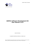
DqEmbCancelEvent
Syntax:
int DqEmbCancelEvent(int
event);
Input:
int handle
DQ_EMBEDDED_EVENT event
Return:
DQ_ILLEGAL_HANDLE
DQ_SUCCESS
Description:
Cancel specified event.
handle, DQ_EMBEDDED_EVENT
Handle to the IOM
Event to cancel
Invalid IOM handle
Command processed successfully
32