1
7743693 11-2004 (Tab 6)
USER & INSTALLATION
INSTRUCTIONS
User & installation
Instructions
User & installation
Instructions
QL Boat trim system
QL Boat trim system
User & installation
Instructions
User & installation
Instructions
QL Boat trim system
QL Boat trim system
User & installation
Instructions
User & installation
Instructions
QL Boat trim system
QL Båttrimsystem
IMPORTANT!
VIGTIGT!
This batch with its accompanying instructions is produced for
Volvo Penta’s service workshops, boat-builders, machine manufacturers and other authorized workshops which have personnel
with qualified professional training.
Dette sæt med tilhørende monteringsvejledning er blevet udviklet for Volvo Pentas serviceværksteder, bådebyggere, maskinproducenter og andre autoriserede værksteder, som har
medarbejdere med kvalificeret, faglig uddannelse.
The installation instructions are only produced for professional use
and are not intended for non-professional use. Volvo Penta will not
assume any liability whatsoever for damage incurred, either damage to materials or personal injury, which may result if the installation instructions are not followed or if the work is carried out by
non-professional personnel.
Monteringsvejledningen er udelukkende beregnet til professionel anvendelse og ikke til hobby- eller fritidsbrug. Volvo Penta
påtager sig intet som helst ansvar for eventuelle skader på såvel materiel som personer, som kan være en følge af at monterings-vejledningens anvisninger ikke blev overholdt, eller hvis
arbejdet blev udført af ikke-professionelt personale.
WICHTIG!
TÄRKEÄÄ!
Dieser Satz mit vorliegender Einbauanleitung ist für Volvo Penta
Kundendienst-werkstätten, Werften, Maschinenbauer und für andere ermächtigte Werkstätten mit beruflich geschultem Personal
vorgesehen.
Tämä sarja ja asennusohje on tarkoitettu Volvo Pentan huoltokorjaamoille, veneenrakentajille, konevalmistajille ja muille valtuutetuille korjaamoille, joiden henkilökunta on saanut pätevän
ammattikoulutuksen.
Die Einbauanleitung ist nur für den berufsmäßigen Gebrauch vorgesehen und nicht für unprofessionelle Anwendung gedacht. Volvo
Penta übernimmt nicht die geringste Haftung für irgendwelchen
Schäden an Personen oder Sachen, die als Folge einer Nichtbefolgung der Einbauanleitung oder wegen Ausführung der darin beschriebenen Arbeiten durch nicht beruflich geschulte Personen
entstehen.
Asennusohje on tarkoitettu ainoastaan ammattikäyttöön. Volvo
Penta ei vastaa mahdollisista materiaali- tai henkilövahingoista,
joita asennusohjeen laiminlyöminen tai ammattitaidottoman henkilökunnan suorittama asennustyö voi aiheuttaa.
IMPORTANT!
Ce kit, avec instructions de montage, est destiné aux ateliers de
service Volvo Penta, aux constructeurs de bateaux et autres ateliers de construction agréés avec un personnel qualifié.
Les instructions de montage sont exclusivement conçues pour
une utilisation professionnelle. Volvo Penta se dégage de toute
responsabilité pour d’éventuels endommagements, corporels ou
matériels, résultant du non respect des instructions ou d’un travail
effectué par un personnel non compétent.
IMPORTANTE!
BELANGRIJK!
Deze set met de bijgevoegde montage-aanwijzing is ontwikkeld
voor de werkplaatsen van Volvo Penta, botenbouwers,
machinefabrikanten en overige bevoegde werkplaatsen, die
personeel hebben met een gekwalificeerde vakopleiding.
De montage-aanwijzing is alleen ontwikkeld voor professioneel
gebruik en is niet bedoeld voor niet-professioneel gebruik.
Volvo Penta neemt geen enkele verantwoordelijkheid op zich
voor eventuele schade, zowel materiële schade als persoonlijk
letsel, die het gevolg kan zijn als de montage-aanwijzing niet
wordt gevolgd, of als het werk wordt uitgevoerd door niet-vakkundig personeel.
IMPORTANTE!
El presente juego con las instrucciones de montaje se destina a
los talleres de servicio Volvo Penta, constructores de embarcaciones y máquinas y a otros talleres autorizados que cuentan con
personal capacitado.
Este jogo, juntamente com as respectivas instruções de montagem, foi concebido para as oficinas de serviço da Volvo
Penta, construtores navais, construtores de máquinas e outras
oficinas autorizadas, com pessoal devidamente formado.
Las instrucciones de montaje están destinadas únicamente para
uso profesional, por lo que Volvo Penta no aceptará responsabilidad alguna por cualquier daño, tanto personal como material, resultado de no haber seguido las instrucciones de montaje o de
haber sido efectuado el trabajo por personal que no está debidamente capacitado.
As instruções de montagem foram concebidas unicamente
para utilização profissional e não se destinam a utilização não
profissional. A Volvo Penta não se responsabiliza por quaisquer
danos eventuais, tanto materiais como pessoais, que possam
resultar no caso de as instruções de montagem não serem
seguidas, ou se os trabalhos forem executados por pessoal
não profissional.
IMPORTANTE!
Questo kit e le relative istruzioni di montaggio sono stati realizzati
per le officine di servizio Volvo Penta, i cantieri, i fabbricanti di
macchine e tutte le altre officine autorizzate il cui personale ha
ricevuto un addestramento qualificato e specializzato.
Le istruzioni di montaggio sono state redatte esclusivamente per
uso professionale e non sono adatte all’uso non professionale. La
Volvo Penta non si assume alcuna responsabilità per eventuali
danni alle cose o alle persone, derivanti da trascuratezza nel seguire le istruzioni di montaggio oppure dall’esecuzione dei lavori
da parte di personale non qualificato.
VIKTIGT!
Denna produkt med föreliggande monteringsanvisning är
framtagen för Volvo Pentas serviceverkstäder, båtbyggare,
maskintillverkare och övriga auktoriserade verkstäder som har
personal med kvalificerad fackutbildning.
Monteringsanvisningen är enbart framtagen för yrkesbruk och är
inte avsedd för icke yrkesmässig användning. Volvo Penta
påtager sig inget som helst ansvar för eventuella skador, såväl
materiella som personskador, som kan bli följden om monteringsanvisningen ej följs, eller om arbetet utförs av icke yrkeskunnig
personal.
Óçìáíôéêü!
Ç ðáñôßäá áõôÞ ìáæß ìå ôéò ïäçãßåò ðïõ ôç óõíïäåýïõí,
ðáñÜãåôáé ãéá ôá óõíåñãåßá ôçò Volvo Penta, ãéá
êáôáóêåõáóôÝò óêáöþí, êáôáóêåõáóôÝò ìç÷áíçìÜôùí
êáé Üëëá åîïõóéïäïôçìÝíá óõíåñãåßá ôá ïðïßá áðáó÷ïëïýí
åîåéäéêåõìÝíï, êáôÜëëçëá åêðáéäåõìÝíï ðñïóùðéêü.
Ïé ïäçãßåò åãêáôÜóôáóçò ðáñÜãïíôáé ìüíï ãéá
åðáããåëìáôéêÞ ÷ñÞóç êáé äåí ðñïïñßæïíôáé ãéá ÷ñÞóç áðü
åñáóéôÝ÷íåò. Ç Volvo Penta äåí áíáëáìâÜíåé êáìßá åõèýíç
ãéá æçìßåò, åßôå óå õëéêÜ åßôå óå Üôïìá, ç ïðïßá ìðïñåß íá
óõìâåß åÜí äåí ôçñçèïýí ïé ïäçãßåò åãêáôÜóôáóçò, Þ åÜí
ïé åñãáóßåò äåí ãßíïõí áðü åðáããåëìáôßåò.
CONTENT
Presentation of the QL Boat Trim System .................................................................... 2
Sizing guidelines ........................................................................................................... 3
Component guide.......................................................................................................... 4
Installation of the QL Boat Trim System ....................................................................... 5
System start up .............................................................................................................. 8
Operating the system .................................................................................................... 9
Error codes .................................................................................................................. 10
Maintenance ................................................................................................................ 10
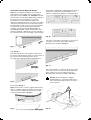
Presentation of the QL Boat Trim System
Fig. 2
41 mm (1.6”)
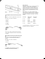
The system comprises:
A. Control Unit
B. Control Panel
C. Interceptor Units
D. Cable between Control Unit and Interceptor Unit
35 mm
(1.4”)
180 mm (7.1”)
E. Cable between Control Unit and Control Panel
The system is designed for planing boats, max boat
speed of 50 knots (57 miles/h). The system can also be
used on semi-planing boats, see sizing guide lines.
The Interceptor units are available in two lengths, 300
mm (12") and 450 mm (18"). They can be installed
individually or side by side, i.e. two units on each side of
the transom (300 + 300 (12" + 12"), 300 + 450 (12" + 18")
or 450 + 450 (18" + 18")).
B
Control panel (B)
The control panel is equipped with 4 push buttons for
smooth operation of the trim system. For push button
functions, see Operating the system. The panel is also
equipped with two rows of LEDs for exact trim indication.
Length
Width
Height
Hole
cutting
(mm/inch)
(mm/inch)
(mm/inch)
(mm/inch)
83/3.3
68/2.7
13/0.5
52/2.0*
* Surface mounted, see fig 20 (A).
Fig. 1
E
Fig. 3
A
83 mm (3.3”)
68 mm (2.7”)
13 mm (0.5”)
D
D
52 mm (2.1”)
C
52 mm (2.1”)
max. 20 mm
(0.8”)
C
Interceptor unit (C)
Control unit (A)
The control unit is the brain of the system, and is
available in two versions, one for 1 pair of Interceptors
and one for 2 pairs of Interceptors. Ambient operating
temperature: Min -40°C, Max +85°C.
Length
(mm/inch)
Width
(mm/inch)
Height
(mm/inch)
180/7.1
35/1.4
41/1.6
Two different sizes are available.
Length
Width
Height
(mm/inch)
(mm/inch)
(mm/inch)
300/11.7
100/3.9
42/1.7**
450/17.7
100/3.9
42/1.7**
** Outside transom.
Each interceptor unit is supplied with necessary
stainless steel screws, for installation in fibre-glass hulls.
Note! Maximum stroke of the Interceptor blade is
35 mm (1.4”).
Sizing guide lines
42 mm
(1.7”)
100 mm
(3.9”)
Fig. 4
300 mm (12”)
450 mm (18”)
Cable between Control Unit and Control Panel
(D)
Many factors affect the choice of properly sized trim unit
configurations, and the ultimate responsibility for
selection is up to the boat owner/boat builder. These
sizing recommendations are based on average boat
performance. Your choice may vary based on power,
engine configuration, weight distribution, type of boat
and use.
When making a choice, please remember that the
largest interceptor configuration that will comfortably fit
on the transom will be the most efficient. The QL Boat
Trim System is designed to fully replace conventional
trim tabs.
Each end of the cable is equipped with a 6-pole socket
plug.
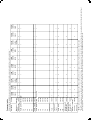
Boat length
Single engine
installation
Five lengts of the cable are available i.e:
15' - 24'
QL300
* 5 m/16.4 ft
22' - 30'
QL450
QL300
* 7 m/23 ft
28' - 34'
QL450
QL450
* 9 m/29.5 ft
32' - 44'
QL450 + QL300
QL450
* 11 m/36 ft
42' - 50'
QL450 x 2
QL450 x 2
Twin engine
installation
* 13 m/42.6 ft
For semi-planing hulls, it may be necessary to increase
the length of the trim unit configuration.
Fig. 5
There is also a 6-pole Y-cable and a 6-pole extension
cable available, used when more than one helm station
is installed.
Cable between Control Unit and Interceptor Unit
(E)
Each end of the cable is equipped with 4-pole socket
plug and one of the ends also with an installation
grommet.
Two lengts of the cable are available, i.e:
* 2.5 m/8.2ft
* 4 m/13.1ft
Fig. 6
For installation of the components, see chapter
Installation of the QL Boat Trim System.
Part No.
889550
889551
889552
888013
3588972
7m
9m
11 m
13 m
6-pole T-cable
874781
874782
874783
7m
9m
11 m
3817172
966689
2
2
2
1
2
2
2
1
2
2
2
4
1
1
1
2x300
+ 2x450
1 helm
station
2
4
4
1
1
1
4x300
1 helm
station
2
4
4
1
1
1
4x450
1 helm
station
2
2
2
1
1
1
1
2
2x300
2 helm
stations
2
2
2
1
1
1
1
2
2x450
2 helm
stations
2
2
2
4
1
1
1
1
2
2x300
+ 2x450
2 helm
stations
2
4
4
1
1
1
1
2
4x300
2 helm
stations
2
4
4
1
1
1
1
2
4x450
2 helm
stations
** Note! The wiring diagrams as specified in these instructions, fig. 23 and 24,show the preferred protection of the Control Unit and the Control Panel (i.e. the connecting the Control Unit and the Control Panel
power supply (positive, red wire) to the boats main fuse box. If the boat does not have a separate fuse box, Volvo Penta resettable 8A breaker may be used.
* Note!For each extra helm station (max 4 helm stations possible), add one control panel, one 6-pole T-cable and one 6-pole extension cable.
breaker 8A**
Resettable
Optional component
Interceptor unit
450mm (18")
1140712
Interceptor unit
300mm (12")
1140714
3817171
4,0m
1140719
2,5m
4-pole cable
2 pairs
Control unit
1-pair
1140718
874780
5m
Control unit
874779
3m
6-pole extension cable (select length)
874789
1
5m
1
2x450
2x300
1
1140717
1 helm
station
1 helm
station
6-pole cable (select length) 1
Control panel
Mandatory components
Description
Before starting the installation, be sure you have all and the appropriate components available. See selection guide below: *
Component guide
Installation of the QL Boat Trim System
Note! Before starting the installation of your QL Boat
Trim System, read carefully the next coming pages!
Especially notice the ”Note!” and ”Important!” remarks.
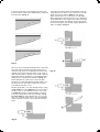
The template , see fig 10, is equipped with pilot holes for
marking on the transom. Place the template on the
transom considering the guidelines as specified above.
The interceptor units (C) fig. 1 and 4 shall be installed on
the transom close to the boat bottom. The exact
positioning is set by the template, included in the
delivery (for detailed instructions, see below). The further
outboard the interceptor units are mounted, the greater
the lateral (side-to-side) control. Position the interceptor
min. 50 mm /2” from the chine and run towards the
centerline of the boat. Boats with Outboard Motors,
Inboard/Outboard (I/Os) or Water Jet installation, must
maintain a minimum of 200 mm /8" from the centerline of
the actual drive unit to the closest edge of the interceptor
Fig. 10
m
50 m
min.
(2”)
If two pairs of Interceptors are installed, i.e. two units on
each side of the transom, leave approx 3mm/1/8"
between the two templates. See fig 11.
mm
200
(8”)
Fig. 7
units. See fig. 7.
Boats with inboard motors may utilize the entire run of
the transom, still leaving min. 50 mm /2” from the chine. If
the boat has strakes reaching the transom, the
interceptor units shall preferrably be installed next to
(1/8
”)
Fig. 11
Preferred location
relative to strakes!
Before the installation is continued, always check there
are no obstacles on the inside of transom (bulkheads,
tanks, fuel lines etc.) that can interfere with or be
damaged by the interceptor installation. See fig 12.
OK location
relative to strakes!
Fig. 8
Warning! Be sure the bilge is completely
ventilated and free of gas fumes. Drilling into a
hull contaminated with gas fumes may cause a
violent explosion.
these strakes. See fig. 8.
Note! If the transom is curved or ragged, shims must be
made of a suitable material, and fixed to the transom, in
order to provide a straight, flat and smooth mounting
surface for the interceptors. See fig. 9.
300/450 mm (12”/18”)
Min. 100 mm
(3.9”)
Fig. 9
Flat mounting surface
Fig. 12
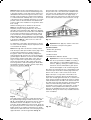
Locate the lower edge of the template flush to the boat
bottom, however no part of the template must overlap the
transom profile. See fig. 13.
If the transom thickness makes it impossible to reach through with the hole cutter, a hole connection from inside
will be necessary to prepare. Note! Be sure that the
edge of the 32 mm/1 1/4" center hole is not damaged
when preparing the through-hull. If the hole is damaged,
the grommet will not fit in a proper way, which may result
in insufficient sealing. The diameter of hole must permit
the the 4-pole plug to pass through. Approx. diameter 25
mm/1" is required, see fig 15.
90°
min. 90 mm (3 1/2”)
Fig. 13
Once you have reached the desired position of the template, keep it firm and steady and mark the pilot holes to
the transom by means of a marking pencil. Remove the
template and check that the pilot holes are all clearly visible. Re-check that no obstacle on the inside of transom
will interfere with the installation nor be damaged by the
drilling, before continuing the installation. See fig. 12.
Fig. 15
Start to drill the hole (center hole) for the interceptor
grommet. Use a drill with diameter smaller than the center drill of the hole cutter that you will use for the final
hole diameter of 32 mm / 1 1/4".
Machine the 32 mm / 1 1/4" hole through transom, using
a high quality hole cutter. Note! Only use a hole cutter of
32 mm / 1 1/4", no other diameters of the tool is accepted. Note! Machine the hole perpendicular to the transom surface (vertically as well as horizontally), see fig.
14 and 15. Note! To check whether the tool you are going to use really will end up in the correct hole diameter,
make a test hole in a piece of wood and check the diameter.
90°
Fig. 14
90°
min. 90 mm (3 1/2”)
Note! Different boats may have different transom constructions, and in case the transom material being used,
is specially sensitive to water and moisture intrusion, it’s
advisable that the transom through hole surface is treated with a water resistant topcoat before the installation
is continued. Moisture and damp may occur from inside
of the transom, due to high bilge water level or to air temperature variances. Be sure that the hole diameter will
not be too tight for the installation of the grommet, due to
thick coating.
Drill the remaining holes as marked on the transom.
Note! The hole dimensions as specified on the
templates (except for the grommet hole), only refer to
glass-fibre reinforced plastic hulls. Eight holes diameter
5.8 mm/7/32" and two holes 3.2 mm/1/8" for the 300 mm/
12" interceptor and twelve holes 5.8 mm/7/32" and two
holes 3.2 mm/1/8" for the 450 mm/18" interceptor. Drill
depth 20 mm/3/4". The hole dimensions are determined
to fit the acid resistant stainless steel screws as supplied
in the delivery. Note! No other screws nor other hole
dimensions are accepted.
For aluminium or steel hulls, other fasteners e.g. machine screws, washers and nuts may be required, however
not included in the delivery.
Note! All through hull holes must be carefully sealed!
Push the 4-pole cable (the end with only the plug socket,
i.e. without the grommet) from outside of transom,
through the center hole and alternately pull/push the
entire length through the transom, however leaving the
grommet approx. 50 mm/2" out from the transom. Note!
Check that the grommet easily slides on the cable casing. If not, drip some soapy water into the grommet
sleeve that surrounds the cable casing and recheck.
Turn the grommet so that the marking ”UP” will be directed upwards and twist the cable so that the 4-pole plug
will fit into the grommet . See fig. 16.
The interceptor unit is equipped with an integrated gasket, part of the front cover, which seals towards the transom surface, thus avoiding water spray between the interceptor unit and the transom. Now apply amply of
marine sealant (see specification) around the interceptor
neck as well as around each of the screw holes, see fig.
17.
Fig. 17
Important! Never apply any sealant on the surface below the lower part of the gasket.
Specified sealants:
* Sikaflex-291 (preferred)
* Boatlife Life Calk
* Boatlife Life Seal
* 3M 4200 Marine Adhesive Sealant
Important! Do not use any other type of sealing
than those specified above. Never use sealing of
hard caulk type. For all handling, preparation of
surfaces, applying, cleaning etc. always follow the
instructions and recommendations given by the
manufacturer/supplier of the sealant being used.
Now press the 4-pole plug into the corresponding socket
in the interceptor neck. See to that the plug reaches the
bottom of the socket, a ”click sound” can be noticed.
Apply a thin layer of soapy water on the inside of the
grommet (use your finger). See fig. 16. Move the interceptor unit carefully against the transom, so that the neck
enters into the grommet. It might be necessary to pull the
cable simultaneously from inside of the transom. Be sure
the cable follows smoothly through the grommet and that
it does not twist inside the grommet. Once you have
reached the correct position of the interceptor, it´s time to
insert the screws (included in the delivery), and screw
them into the predrilled transom holes and tighten them
alternately. See fig. 18. Remove any residual sealant before it´s hardened.
Fig. 16
Now apply marine sealant (see sealant specification) on
the grommet flange (flange towards the transom), see
fig. 16 , and push/pull the grommet into the hole. Press it
towards the transom, and adjust it so the two flange
holes fit to the pre-drilled holes in the transom. Screw up
the grommet (use the two small screws as supplied) and
tighten. Remove any residual sealant before it’s hardened. Push the cable from inside, so that the plug reaches
approx 50 mm/2" out from the grommet. See fig. 18.
Fig. 18
The control unit shall be firmly fixed on a dry and easily
accessible location, e.g. inside of transom. Screws are
not included. Check that the distances from the control
unit to each of the interceptors are not too long, i.e. the
connecting cables are max 2.5 meters or 4 meters long
(8.3’ or 13.1’), depending on your choice.
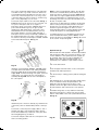
Connect the 4-pole cables to the control unit. See fig. 1,
2 and 19. There are two versions of the control unit, one
for 1-pair of interceptors and one for 2-pairs of
interceptors. Each control unit is equipped with four 4pole sockets marked P2 (port 2), P1 (port 1), SB1
(starboard 1), SB2 (starboard 2), one 6-pole socket
marked AUX and one red cable (marked +) and one
black cable (marked -) for power supply. One pair of
interceptors: use P1 for the port interceptor and SB1 for
the starboard interceptor. Two pairs of interceptors: use
P1 and P2 for the two port interceptors and SB1 and SB2
for the starboard interceptors. See fig. 19.
Note! For Volvo Penta EVC EC engines, the red cable
must not be connected directly to the start key, but instead to the relay for external accessories. Note! Always
check with your engine supplier whether there are any
other recommendations or requirements that concern
the wiring to the start lock. Protect the installation by a 38A fuse on the plus cable.
If more than one helm station is installed, only the main
station control panel (red cable) shall be connected to
the start lock or to the relay, as described above. For
mechanical governed engines as well as for Volvo
Penta EVC MC engines, see wiring diagram fig 23 and
for EVC EC engines, see wiring diagram fig 24.
If a suitable fuse box is not available in the boat, Volvo
Penta resetable 8A breaker, part No 966689, can be
used for protection of the installation. See fig. 21 as well
as the section ”Component guide”.
9.
System start up
Fig. 21
Once the QL Boat Trim System is mechanically installed
and all electrical cables are connected, it’s time to carry
out the calibration of the system before the system can
be operated. This is done in order to determine the
blade position when fully retracted and fully out
respectively. The calibration is performed as follows:
1.
Turn on the main switch.
Fig. 19
Install the control panel (B), see fig. 1, 3 and 20, easily
accessible at the helm station. Hole cutting is diameter
52 mm (2”). See fig. 3. Use the gasket, included in the
supply (20 A). For flush mounting of the panel, press the
center section out and use the rest of the gasket for
assembly see fig. 20 B. See also the hole template for
the control panel.
A
B
2.
Press the upper and lower button on the control panel
simultaneously and keep them in.
3.
Turn the start key to running position (without starting the
engine).
4.
Wait minimum 10 sec. until the interceptor blades start to
move out and then release the panel buttons. The
blades may start moving before the 10 sec. have
passed, however the upper and lower buttons must still
be pressed down, until at least 10 sec. have passed.
5.
The blades will go fully out, stop and then retract fully.
Once this has be done in a proper way, the two upper
and two lower LEDS on the control panel will flash twice.
See fig. 22.
Fig. 20
Install the 6-pole connection cable (E) fig. 1 between the
control unit (connector marked AUX) and the control panel.
Connect the control unit power supply cables to 12V or
24V DC (red cable to plus and black cable to minus).
Protect the installation by a 6-8A fuse on the plus cable.
See wiring diagrams fig. 23 and 24.
Connect the red plus cable from the control panel to the
start lock running position.
Fig. 22
This is the confirmation that the calibration is correctly
done. If the calibration was not successful, an error code
will pop up. If starboard interceptor was not successfully
calibrated, the right LEDs, No 6 and 7 will flash. If port
interceptor was not successfully calibrated, the left LEDs,
No 6 and 7 will flash (see also under the headline Error
codes). If this will happen, shut off the power to the
system, and investigate why the blades do not move
(mechanical obstacle, clogged up by paint or acorn
barnacles). Remove the obstacle and recalibrate.
If a control unit for two pairs of interceptor units is used,
but only one pair of interceptors is installed, thus the
control unit is calibrated with only one pair of
interceptors, it is necessary to re-calibrate the system if
another pair of interceptors is installed later on.
If the control unit or any of the interceptor units, for any
reason later on are replaced, the system has to be
recalibrated.
6.
Now the system is ready for operation. Note! In
connection to the boat launch, always check the
interceptor installation regarding water leakage through
the transom! If any leakage, the installation is not
properly done and must be redone.
Operating the system
The control panel has four buttons. The upper button
lowers the blades in paralell (bow down). The lower
button retracts the blades in parallell (bow up). The left
button lowers the starboard blade and retracts the port
blade (tilt port). The right button lowers the port blade
and retracts the starboard blade (tilt starboard). The
blade operation starts when pressing the button and
stops when releasing it. The LED:s on the panel have
variable light intensity in four steps and OFF. By pressing
the left and right buttons simultaneously for approx 1
second, the light intensity of the LED:s takes one step
down. As long as the 2 buttons are pressed in, the
intensity takes one more step down for each 0,5 second.
When the intensity reaches the OFF level, it returns to
maximum intensity again and keeps toggling like this as
long as the 2 buttons are pressed in. When the buttons
are released, the intensity of the LED:s will stay at the
current value. If several panels are connected to the
system, only the panel where the buttons are pressed
will be affected. After power off, the panel LED:s will
restart at maximum light intensity when power on.
When the engine stops (power supply to the panel is
lost), the blades will fully retract after a few seconds.
Note! If more than one helm station is installed, the
engine must be stopped from the main station (the
station where the red cable from the control panel is
connected to 12V or 24V).
Error codes
To help troubleshooting a system that is malfunctioning,
there are some Error Codes (EC) implemented. If an EC
is set, it is communicated to the user by flashing with
some of the LEDs on the control panel. The following
ECs/flashing can occur:
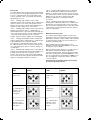
- EC 1; Flashing: LED number 1 and 2 on both
starboard and port side are flashing. Error: Indicates that
a button is stuck on one of the control panels. Action:
Check so that no button is pressed in by mistake, by for
example an object laying on the control panel.
- EC 2; Flashing: LED number 3 and 4 on port side are
flashing. Error: Indicates that no communication is
detected between the control unit and the interceptor(s)
on port side. Action: Check so that the cable(s) between
control unit and the interceptor(s) are connected
properly. Check so that the cable(s) are not damaged.
- EC 3; Flashing: LED number 3 and 4 on starboard
side are flashing. Error: Indicates that no communication
is detected between the control unit and the
interceptor(s) on starboard side. Action: Check so that
the cable(s) between control unit and the interceptor(s)
are connected properly. Check so that the cable(s) are
not damaged.
- EC 4; Flashing: LED number 6 and 7 on port side are
flashing. Error: Indicates that the interceptor blade(s) on
port side are stuck and can not reach the correct
position. Action: Check so that the interceptor blade(s)
are not stuck due to marine growth, dirt, mechanical damage etc. Clean/replace them if neccessary.
- EC 5; Flashing: LED number 6 and 7 on starboard
side are flashing. Error: Indicates that the interceptor
blade(s) on starboard side are stuck and can not reach
the correct position. Action: Check so that the interceptor
blade(s) are not stuck due to marine growth, dirt,
mechanical damage etc. Clean/replace them if
neccessary.
- EC 6; Flashing: The two upper green LEDs are
flashing. Error: Indicates that there is no communication
between the control panel and the control unit. Action:
Check so that the cable between the control unit and the
control panel is connected properly. Check so that the
cable is not damaged.
Maintenance of the system
As for all through hull fittings, regulary check for any
water intrusion where the interceptor units are mounted.
Depending of the type of water condition where the boat
is operated, marine growth can vary from almost nonexistent to extremely severe.
When needed, paint the external surface of the
interceptor unit with anti-fouling. Note! Do not paint any
moving parts, e.g. the blade!
When the boat has been docking for a longer period of
time and the marine environment is aggressive
concerning marine growth, lower the interceptor blade
and clean carefully away any growth. Note! Do not use
any sort of high-pressure cleaning device. Note! Do not
use any aggressive solvents, like acetone, methanol,
corrosive acids etc.
Please keep this Installation and User manual with
your boat´s operating manuals!
Error
code
Flash
pattern
Error
code
1
4
Button stuck
Blade stuck
port
2
5
No communication
between control
unit and port
interceptors
Blade stuck
starboard
3
6
No communication
between control
unit and starboard
interceptors
No communication
between control
unit and control
panel
Flash
pattern
Volvo Penta EVC MC and other mechanical engines
6-8 A
Fig. 23
3-8 A
Volvo Penta EVC EC (electronical engines)
6-8 A
Fig. 24
3-8 A
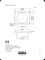
Hole template for control panel
Scale 1:1
CE APPROVAL
Electromagnetic compatibility directive 89/336/EEC
with addition 91/263/EEC
Directive 92/31/EEC
Directive 93/68/EEC
AB Volvo Penta
SE-405 08 Göteborg, Sweden
7744248 11-2004 (Tab 2)
The QL Boat Trim System complies with the
requirements in the following CE standards: