1
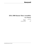
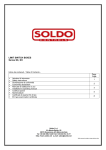
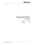
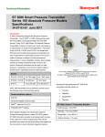
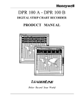
RMA 3000 Remote Meter Assemblies
Specifications
34-ST-03-81 June 2012
Introduction
Overview
The Remote Meter Assembly RMA 3000 functions as an
The Digital Meter DM is used exclusively with Honeywell
output and status indicator for a compatible Honeywell
transmitters operating in the DE (Digital Enhanced) mode.
Smartline Transmitter or as an output indicator for a non-
The DM features a fan style 25 segment bargraph with
Honeywell transmitter operating in a 4-20mA current loop.
digital indication and status displays. The DM digital
The RMA 3000 consists of a meter mounted in an
indicator gives precise output of the transmitter from –199.9
aluminum explosion-proof housing with several protective
to +199.9% of transmitter range. Engineering units are not
paint styles available.
available on the DM.
Four meter types are available for mounting in the RMA
The Analog Meter ME is used with analog output
3000 housing:
transmitters to give % output using a needle-type meter
movement.
the Smart Meter (SM),
the Digital Meter (DM),
The Engineering Units Meter EU provides digital display
the Analog Meter (ME), and
of temperature, pressure, level, flow, or other
the Engineering Unit Display Meter (EU)
measurements in real Engineering Units. This meter
provides a universal solution for 4-20mA measurement
The Smart Meter SM can be used to display either output
displays by converting any 4-20mA signal into an LCD
in % or engineering units appropriate to the transmitter
digital display in the preferred engineering units.
depending on the transmitter type and configuration. The
SM can be used with any one of the following Smartline
The EU Display Meter is available for remote-mount field
Transmitters in either analog or DE mode:
use or can be integrally mounted in the STT250
ST 3000 Smart Pressure Transmitter, or the
Temperature Transmitters or in the STT250 Model STT25H
STT 3000 Smart Temperature Transmitter
with the HART™ protocol.
SM
DM
ME
EU
RMA 3000 Remote Meter Assemblies
2
Highlights of Meter Features
RMA 3000 Remote Meter Assemblies
3
Features and Functions
RMA300 - SM
RMA300 - ME
The Smart Meter (SM) is a digital device that functions as
Function - The ME is an analog device that functions as
an output and status indicator for a compatible Honeywell
an output indicator for any transmitter that operates in the
Smartline Transmitter, or just as an output indicator for a
4-20 mA current mode.
non-Honeywell transmitter operating in a 4 to 20 mA
current loop. It can operate in the analog mode (4-20
Application - The ME can be used as a Remote Meter
mA), or can operate in the Honeywell proprietary Digital
Assembly component with any one of the following
Enhanced (DE) mode.
Smartline Transmitters operating in the analog (4 to 20
mA) mode.
As indicated in the illustration, the SM is similar in
appearance to the DM. That is, they both have a multi-
Electrical Characteristics – The ME is an
segment fan-style bargraph that indicates from 0% to
electromechanical device of the D’Arsonval type. That is,
100%, and both include status indicators. However, the
the current passing through a coil in the meter is used to
SM can be easily distinguished from the DM in that the
deflect a needle to indicate the magnitude of the current,
SM has:
where a current of 4-20 mA represents 0% to 100%.
•
•
17-segment bargraph (compared to 25 for the DM)
The ME can be used in combination with the SM in the
more status indicators than the DM
same loop, provided that the formula presented under the
Three wire connections (Red, Blue, and Yellow) to
other components whereas the DM has two wire
SM description above in electrical characteristics for
multiple meters is obeyed.
connections (Red and Yellow).
•
The SM has a configuration button on the periphery
of the case at lower left.
RMA300 - EU
The EU Display Meter is connected in series with the 420mA loop and is powered by the loop power. It operates
by processing the 4-20mA signal via an analog-to-digital
RMA300 - DM
converter and scaling the digital measurement linearly
Designed for use with Honeywell smart transmitters
into the desired operating range, which the user
operating in the Digital (DE) Communications Mode, the
configures into the meter. The LCD display includes a
DE Meter provides convenient, easy-to-read transmitter
selection of integral engineering units for temperature and
output and loop status indications on its liquid-crystal
pressure applications (for example - °C, °F, in H2O, psi,
display. As shown in the figure, the DE Meter display
etc. and a “K” multiplier that can be included when larger
features a 25-segment bargraph, a digital readout, and a
ranges require it).
set of status messages.
The EU Display Meter also includes a bar-graph display
The 25-segment bargraph gives a gross indication of
of measured signal as a percentage of the 16mA signal
transmitter output from 0 to 100% that can be viewed
span. This enables confirmation from some distance
from up to 30 feet away. The digital readout, a
away that the measurement loop is operating
complement to the bargraph indication, gives a precise
satisfactorily or that attention is required. The meter is
indication of transmitter output from –199.9 to +199.9%
configured by an integral selection switch, which enables
that can be read from up to 10 feet away.
setting the Low (4mA) and High (20mA) display range
limits.
Status messages serve as online diagnostics for various
detectable loop conditions. When the transmitter is in the
square root mode, the DE Meter still displays the
transmitter output from 0 to 100%. The DE Meter has no
square root mode or flow indicator display.
HART™ is a trademark of the Hart Communication
Foundation
RMA 3000 Remote Meter Assemblies
4
RMA300SM Specifications
Operating Conditions
Parameter
Rated
Extreme, Transportation and Storage
Ambient Temperature
-40 to +185 ºF
-40 to +85 ºC
-58 to +194 ºF
-50 to +90 ºC
Relative Humidity
0 – 100%
0 – 100%
Design
Accuracy
Analog (4-20mA) Mode
Honeywell Digital
(DE) Mode
± 0.5% of span
Display Resolution
Bargraph
Digital Readout
± 3% reading
Reproduces the transmitter signal exactly to within its resolution
± 0.05% for ± 199.9 reading range, ± 0.5% for ± 1999 reading range,
± 5% for ± 19990 reading range
Maximum Meter Voltage
(red lead to yellow lead)
42 VDC
Maximum Loop Voltage Drop
(yellow lead to screw
terminal)
2.25 VDC
Maximum Loop Operating
Current
3.6 mA
ATTENTION
The LCD display will turn black between 80 and 90 ºC (176 and 194 ºF), rendering the
display unreadable. This effect is temporary.
RMA300DM Specifications
Operating Conditions
Parameter
Rated
Extreme, Transportation and Storage
Ambient Temperature
-40 to +176 ºF
-40 to +80 ºC
-58 to +194 ºF
-50 to +90 ºC
Relative Humidity
0 – 100%
0 – 100%
Design
Display Resolution
Bargraph
± 4% reading
Digital Readout
± 0.1% reading
ATTENTION
The LCD display will turn black between 80 and 90 ºC (176 and 194 ºF), rendering the
display unreadable. This effect is temporary.
RMA300ME Specifications
Operating Conditions
Parameter
Rated
Extreme, Transportation and Storage
Ambient Temperature
-40 to +176 ºF
-40 to +80 ºC
-58 to +194 ºF
-50 to +90 ºC
Relative Humidity
0 – 100%
0 – 100%
Design
Display Resolution
± 1% reading
RMA 3000 Remote Meter Assemblies
5
RMA300EU Specifications
Operating Conditions
Parameter
Rated
Extreme, Transportation and Storage
Ambient Temperature
-40 to +185 ºF
-40 to +85 ºC
-58 to +194 ºF
-50 to +90 ºC
Relative Humidity
10 – 90%, non condensing
0 – 100%
Design
± 0.5% of span
Digital Display Accuracy
Digital Display Resolution
± 0.05% for ± 199.9 reading range,
± 0.5% for ± 1999 reading range,
± 5% for ± 19990 reading range
± 50% for ± 199900 reading range
± 500% for ± 1999000 reading range
± 5000% for ± 19990000 reading range
Bargraph % Display Resolution
± 3% of reading on 17-segment scale
Power Supply Volts drop across meter
2.3 VDC with reverse polarity protection.
Connection Polarity
Yellow = Positive (+ve); Blue = Negative (-ve)
Minimum Loop Current
3.6 mA
Shown as:
199.9
1999
19990
199.9 K
1999 K
19990 K
Available Engineering Units
Integral LCD indicator
As stick on label
ºF, ºC, %, in H2O, GPH, GPM, mmHg, PSI, PSIA
Wide selection of printed units for temperature, pressure, and flow.
All Displays
Certification Conditions
Installation
Explosionproof/Flameproof
Ambient Limits
–4ºF to +149ºF
–20ºC to +65ºC
Intrinsically Safe
–40ºF to +140ºF
–40ºC to +60ºC
Enclosure Specifications
Material of Construction
Aluminum (SS available)
Number of Conduit Openings
Two ½” NPT openings
Available Adapters
½ NPT to M-20 316SS conduit adapter
½ NPT to ¾ NPT 316SS conduit adapter
Paint
Beige or Red Epoxy
RMA 3000 Remote Meter Assemblies
6
Approval and Certification
Model Selection Guide, Table III
Approval
Body
None
Approval Type
Location or Classification
None
Explosionproof,
Dust Ignitionproof,
Non-Incendive
Factory
Mutual
Intrinsically Safe
Class I, Div. 1, Groups A, B, C, D;
Class II, III, Div. 1, Groups E, F,G;
Class I, Div. 2, Groups A, B, C, D
(DM, ME & SM, T4 at 40ºC)
Class I, II, III, Div. 1, Groups A,B,C,D,E,F,G;
(DM, ME & SM, T4 at 40ºC)
Enclosure: Type 4X
Explosion Proof &
Dust Ignition Proof
CSA
Intrinsically Safe
Class I, Div. 1, Groups B, C, D;
Class II, III, Div. 1, Groups E, F, G
(DM, ME & SM, T4 at 93ºC; EU, T4 at 60ºC)
Class I, II, III, Div. 1, Groups A,B,C,D,E,F,G;
(DM, ME & SM, T4 at 93ºC; EU, T4 at 60ºC)
Enclosure: Type 4X
Intrinsically Safe
Flameproof
Non Sparking
ATEX *
LCIE 02ATEX 6178X
II 1 GD (Table II= TG or TB);
II 2 GD (Table II= XC or XR);
Ex ia IIC T5 (Ta= -40° to 60°C)
Ex tD A21 IP6X T95°C (at Ta = 85°C) or T80°C (at Ta = 65°C)
Multiple Marking **
Intrinsically Safe,
Flameproof and Non
Sparking
IECEx
SAEx
LCIE 02ATEX 6178X
II 1 GD (Table II= TG or TB);
II 2 GD (Table II= XC or XR);
Ex ia IIC T5 (Ta= -40° to 60°C)
Ex tD A21 IP6X T95°C (at Ta = 85°C) or T80°C (at Ta = 65°C)
LCIE 02ATEX6177X
II 2 GD
Ex d IIC T6(Ta= -40 oC to 65 oC) or T5 (Ta= -40 oC to 85 oC)
Ex tD A21 IP6X T95°C (at Ta = 85°C) or T80°C (at Ta = 65°C)
HON 02.202
II 3 GD
Ex nA IIC T6 (Ta= -40 oC to 65 oC) or T5 (Ta= -40 oC to 85 oC)
Ex tD A22 IP6X T95°C (at Ta = 85°C) orT80°C (at Ta = 65°C)
Intrinsically Safe
And
Flameproof
Intrinsically Safe
And
Flameproof
LCIE 02ATEX6177X
II 2 GD
Ex d IIC T6(Ta= -40 oC to 65 oC) or T5 (Ta= -40 oC to 85 oC)
Ex tD A21 IP6X T95°C (at Ta = 85°C) or T80°C (at Ta = 65°C)
HON 02.202
II 3 GD
Ex nA IIC T6, -40 ≤ Ta ≤ 65°C
Ex tD A22 IP6X T95°C (at Ta = 85°C) orT80°C (at Ta = 65°C)
Ex ia IIC T4 (Ta = -40°C to +85°C), T5 (Ta = -20°C to +60°C)
Ex d IIC T6 (Ta = -20°C to +65°C), T5 (Ta = -40°C to +85°C)
Ex ia IIC T4 (Ta = -40°C to +85°C), T5 (Ta = -20°C to +60°C)
Ex d IIC T6 (Ta = -20°C to +65°C), T5 (Ta = -40°C to +85°C)
* See ATEX Installation requirements in the Operator manual
RMA 3000 Remote Meter Assemblies
7
Model Selection Guides are subject to change and are inserted into the specifications as guidance only.
Prior to specifying or ordering a model check for the latest revision Model Selection Guides which are published at:
https://www.honeywellprocess.com/en-US/pages/default.aspx
Model Selection Guide
34-ST-16U-46
Issue 31
Page 1 of 3
RMA 3000
Remote Meter Assemblies
Model Selection Guide
Instructions
● Select the desired key number. The arrow to the right marks the selection available.
● Make one selection from Table I. Select Table II options as desired.
Key Num ber
RMA300
I
-
__
II (Optional)
__, __
-
-
III
__
Availability
KEY NUMBER
Description
Selection
RMA300
Remote Meter
TABLE I - METER TYPE
Smart Meter
Digital Meter
EU Meter
Analog Meter
SM (R600)
SM
DM
EU
ME
DM
EU
m
b
ME
TABLE II - OPTIONS
No Selection
00
Meter Housing Options
Stainless Steel Customer wired-on Tag (4 lines, 28 characters per line,
TG
customer supplied information)
Stainless Steel Customer wired-on Tag (blank)
TB
Mounting Bracket - Carbon Steel
MB
SB
Mounting Bracket - SS
A1
1/2" NPT to M20 316 SS Conduit Adapter (BASEEFA EEx d IIC)
1/2" NPT to 3/4" NPT 316 SS Conduit Adapter
A2
No Conduit Entry plugs supplied
Wiring Entry
For conduit plugs,adapters and cable glands see the "Supplemenatal
Plugs
Accessories and Kits" section below this table
XC
Beige Epoxy Painted Housing
XR
Red Epoxy Painted Housing
End Cap Live Circuit Warning Label in Spanish
SP
End Cap Live Circuit Warning Label in Portuguese
PG
End Cap Live Circuit Warning Label in Italian
TL
End Cap Live Circuit Warning Label in German
GE
Warranty Options and Certificates
UM
User's Manual Paper Copy
F3
Certificate of Conformance (F2474)
W1
Additional Warranty - 1 Year
W2
Additional Warranty - 2 Years
W3
Additional Warranty - 3 Years
W4
Additional Warranty - 4 Years
●
●
●
●
●
b
b
g
h
b
●
●
b
a
a
a
a
●
●
●
●
●
●
b
b
RMA 3000 Remote Meter Assemblies
8
Model Selection Guide
34-ST-16U-46
Issue 31
Page 2 of 3
Supplemental Accessories and Kits
Conduit Plugs and Adapters m ay be ordered separately (M eter Assemblies come with plastic dust plugs as standard)
Description
Certified conduit plugs for CSA, ATEX and IECEx
1/2 NPT Certified Socket Plug
1/2 NPT Certified Socket Plug
Certified adapters for CSA, ATEX and IECEx
1/2 NPT (male) to 3/4 NPT (female)
1/2 NPT (male) to M20 (female)
Certified cable glands for UL and cUL
1/2 NPT
Material of Construction
Part Number
Zinc-plated Carbon Steel
316 SS
50021832-501
50021832-502
316 SS
316 SS
50000682-501
51202409-501
Brass Nickel plated
50023212-501
** Consult Honeyw ell Order Entry System for current parts pricing
TABLE III - APPROVALS
Approval
Approval Type
Body
None
None
Factory
Mutual
Explosionproof,
Dust Ignitionproof,
Non-Incendive
Intrinsically Safe
Enclosure Rating
Explosion Proof &
Dust Ignition Proof
CSA
Intrinsically Safe
Enclosure Rating
Intrinsically Safe
Zone 0/1 / Zone 20/21
ATEX*
Flameproof
Zone 1 / Zone 21
Non-Sparking
Zone 2 / Zone 22
RMA300
Location or Classification
Availability
Selection
9X
Class I, Div. 1, Groups A, B, C, D;
Class II, III, Div. 1, Groups E, F, G;T4 at 40ºC
Class I, Div. 2, Groups A, B, C, D
1C
Class I, II, III, Div. 1, Groups A,B,C,D,E,F,G;
T4 at 40ºC
Type 4X
Class I, Div. 1, Groups B, C, D;
Class II, III, Div. 1, Groups E, F, G
(DM, ME & SM, T4 at 93ºC; EU, T4 at 60ºC)
2J
Class I, II, III, Div. 1, Groups A,B,C,D,E,F,G;
(DM, ME & SM, T4 at 93ºC; EU, T4 at 60ºC)
Type 4X
II 1 GD (Table II = TG or TB);
II 2 GD (Table II = XC or XR)
Ex ia IIC T5 (Ta = –20°C to +60°C),
3U
Ex tD A21 IP6X T95°C (at Ta = 85°C) or
T80°C (at Ta = 65°C)
II 2 GD Ex d IIC T5 (Ta = –40°C to +85°C)
T6 (Ta = –40°C to +65°C)
Ex tD A21 IP6X T95°C (at Ta = 85°C) or
33
T80°C (at Ta = 65°C)
Enclosure IP66/67
II 3 GD Ex nA, IIC T5 (Ta = –40°C to +85°C)
T6 (Ta = –20°C to +65°C)
3Y
Ex tD A22 IP6X T95°C (at Ta = 85°C) or
T80°C (at Ta = 65°C)
(continued on next page)
b
RMA 3000 Remote Meter Assemblies
9
Model Selection Guide
34-ST-16U-46
Issue 31
Page 3 of 3
II 1 GD (Table II TG or TB)
II 2 GD (Table II= XC or XR)
Ex ia IIC T5 (Ta= -40° to 60°C)
II 2 GD
ATEX*
Multiple Marking **
Ex d IIC T6 (Ta= -40 oC to 65 oC) or
T5 (Ta = –40°C to +85°C)
Int. Safe, Zone 0/1, or
Flameproof, Zone 1, or Ex tD A21 IP6X T95°C (at Ta = 85°C) or
T80°C (at Ta = 65°C)
II 3 GD Ex nA IIC T6 (Ta = –20°C to +65°C)or
T5 (Honeywell)
T5 (Ta = –40°C to +85°C)
Ex tD A22 IP6X T95°C (at Ta = 85°C) or
T80°C (at Ta = 65°C)
Non-Sparking Zone 2
Enclosure IP66/67
Flameproof, Zone 1
Ex d IIC T6 (Ta = -20°C to +65°C), T5 (Ta =
–40°C to +85°C)
Enclosure IP66/67
IECEx
Intrinsically safe,
Zone 0/1
Flameproof, Zone 1
SAEx
Intrinsically safe,
Zone 0/1
3C
CA
Ex ia IIC T4 (Ta = -40°C to +85°C), T5 (Ta =
–20°C to +60°C)
Ex d IIC T6 (Ta = -20°C to +65°C), T5 (Ta =
–40°C to +85°C) Enclosure IP66/67
Ex ia IIC T4 (Ta = -40°C to +85°C), T5 (Ta =
–20°C to +60°C)
ZA
* See ATEX installation requirements in the Operator's Manual
**The user must determine the type of protection required for installation of the equipment. The
user shall then check the box [√] adjacent to the type of protection used on the equipment certification
nameplate. Once a type of protection has been checked on the nameplate, subsequently the
equipment shall not be reinstalled using any of the other certification types.
RESTRICTIONS
Restriction
Letter
Table
a
III
Available Only With
Selection
Table
Not Available With
Selection
3U,33,3Y,3C
Select only one option from this group
b
g
III
3U, 33, 3Y, 3C, CA, ZA
h
III
1C, 2J
m
I
9X, 1C, 2J, 33, 3Y
III
3U, 3C, CA, ZA
Notes: See 13:ST-OE-9 for OMS Order Entry Information including TC, manuals, certificates, draw ings and SPINS.
See 13:ST-27 for Published Specials w ith pricing.
Ordering Example: RMA300-SM-MB,TG-2J
RMA 3000 Remote Meter Assemblies
10
ASIA PACIFIC
EMEA
NORTH AMERICA
SOUTH AMERICA
(TAC)
[email protected]
Honeywell Process Solutions,
Phone: + 80012026455 or +44
(0)1202645583
FAX: +44 (0) 1344 655554
Email: (Sales)
[email protected]
or
(TAC)
[email protected]
Honeywell Process Solutions,
Phone: 1-800-423-9883
Or 1-800-343-0228
Honeywell do Brasil & Cia
Phone: +(55-11) 7266-1900
FAX: +(55-11) 7266-1905
Email: (Sales)
[email protected]
or
(TAC)
[email protected]
Email: (Sales)
[email protected]
or
(TAC)
[email protected]
Australia
Honeywell Limited
Phone: +(61) 7-3846 1255
FAX: +(61) 7-3840 6481
Toll Free 1300-36-39-36
Toll Free Fax:
1300-36-04-70
China – PRC - Shanghai
Honeywell China Inc.
Phone: (86-21) 5257-4568
Fax: (86-21) 6237-2826
Singapore
Honeywell Pte Ltd.
Phone: +(65) 6580 3278
Fax: +(65) 6445-3033
South Korea
Honeywell Korea Co Ltd
Phone: +(822) 799 6114
Fax: +(822) 792 9015
The information and specifications in this document are subject to change without notice
For More Information
Learn more about how Honeywell’s RMA 3000 Remote
Meter Assemblies can provide accurate transmitter output,
visit our website www.honeywellprocess.com/RMA-3000Remote-Meter-Assemblies or contact your Honeywell
account manager.
Honeywell Process Solutions
1860 West Rose Garden Lane
Phoenix, Arizona 85027
Tel: 1-800-423-9883 or 1-800-343-0228
www.honeywellprocess.com
34-ST-03-81
June 2012
© 2011 Honeywell International Inc.