1
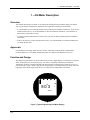
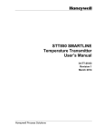
Engineering Unit Meter
User Guide
Doc. No.:
34-ST-25-18
Revision:
3
Revision Date:
5/08
_________________________________________________________________________________________________________
Honeywell Process Solutions
Notices and Trademarks
Notices and Trademarks
Copyright 2008 by Honeywell International Inc.
Revision 3 May, 2008
Honeywell warrants goods of its manufacture as being free of defective materials and faulty workmanship. Contact
your local sales office for warranty information. If warranted goods are returned to Honeywell during the period of
coverage, Honeywell will repair or replace without charge those items it finds defective. The foregoing is Buyer's sole
remedy and is in lieu of all other warranties, expressed or implied, including those of merchantability and
fitness for a particular purpose. Specifications may change without notice. The information we supply is believed
to be accurate and reliable as of this printing. However, we assume no responsibility for its use.
While we provide application assistance personally, through our literature and the Honeywell web site, it is up to the
customer to determine the suitability of the product in the application.
Honeywell Process Solutions
512 Virginia Drive
Fort Washington, PA 19034
Honeywell is a U.S. registered trademark of Honeywell
Other brand or product names are trademarks of their respective owners.
ii
EU Meter User Guide
Revision 3
4/08
About This Document
About This Document
Revision Notes
The following list provides notes concerning all revisions of this document.
Doc ID
Rev ID
34-ST-25-18
Date
Notes
st
Revision 0
9/01
1
Revision 1
7/02
Deleted installation information for Model STT 350 and for remote
mounting.
Revision 2
6/05
Deleted CE info
Revision 3
5/08
Added ATEX Information
issue of document.
Contacts
World Wide Web
The following lists Honeywell’s World Wide Web sites that will be of interest to our industrial automation and
control customers.
Honeywell Organization
Corporate
WWW Address (URL/e-mail)
http://www.honeywell.com
Telephone
Contact us by telephone at the numbers listed below.
Organization
United States and Canada
Revision 3
4/08
Honeywell Technical Assistance
Center
EU Meter User Guide
Phone Number
1-800-423-9883 Tech. Support
1-800-525-7439 Service
iii
About This Document
Symbol definitions
The following table lists those symbols used in this document to denote certain conditions.
Symbol
Definition
This CAUTION symbol on the equipment refers the user to the Product Manual for
additional information. This symbol appears next to required information in the manual.
This WARNING symbol on the equipment refers the user to the Product Manual for
additional information. This symbol appears next to required information in the manual.
WARNING: risk of electrical shock. This symbol warns the user of a potential shock
hazard where HAZARDOUS LIVE voltages greater than 30 Vrms, 42.4 Vpeak, or 60
VDC may be accessible.
ATTENTION, Electrostatic Discharge (ESD) hazards. Observe precautions for
handling electrostatic sensitive devices
Protective Earth (PE) terminal. Provided for connection of the protective earth (green
or green/yellow) supply system conductor.
Functional earth terminal. Used for non-safety purposes such as noise immunity
improvement. NOTE: This connection shall be bonded to protective earth at the
source of supply in accordance with national local electrical code requirements.
Earth Ground. Functional earth connection. NOTE: This connection shall be bonded to
Protective earth at the source of supply in accordance with national and local electrical
code requirements.
Chassis Ground. Identifies a connection to the chassis or frame of the equipment shall
be bonded to Protective Earth at the source of supply in accordance with national and
local electrical code requirements.
iv
EU Meter User Guide
Revision 3
4/08
Contents
Contents
1 —EU Meter Description...........................................................................................1
Overview..............................................................................................................................................1
Approvals.............................................................................................................................................1
Function and Design............................................................................................................................1
Meter Description.............................................................................................................................2
Display Features ..............................................................................................................................3
Operating Conditions and Specifications.........................................................................................5
Meter Display at High and Low Temperature Extremes..................................................................5
2 —EU Meter Installation ...........................................................................................6
Overview..............................................................................................................................................6
For more information........................................................................................................................6
Getting Started ....................................................................................................................................6
Tools Required.................................................................................................................................6
Parts Required .................................................................................................................................6
Preparation ......................................................................................................................................6
Integral Mounting with STT 3000 Temperature Transmitters..............................................................7
3 – Setup and Operation ............................................................................................9
Overview..............................................................................................................................................9
Guidelines for setting up the EU meter............................................................................................9
Setup Parameters and Functions........................................................................................................9
Overview of Setup Displays and Operations .................................................................................10
General Procedure for Parameter Access.....................................................................................11
Set Up Lower Range Value and Upper Range Value .......................................................................12
Selecting Engineering Units ..............................................................................................................17
Calibration .........................................................................................................................................19
In-loop Calibration..........................................................................................................................19
Calibrate LO and Calibrate HI........................................................................................................19
Setup Summary.................................................................................................................................20
Operation...........................................................................................................................................22
Self-test Diagnostic ........................................................................................................................22
LCD Check.....................................................................................................................................22
Normal Operating Indications ........................................................................................................23
Revision 3
4/08
EU Meter User Guide
v
Tables
Tables
Table 1 Engineering Unit Display Indicator Description ..............................................................................................4
Table 2 EU Meter Specifications...................................................................................................................................5
Table 3 Installing EU Meter in STT 3000 .....................................................................................................................7
Table 4 Example - Setting LRV and URV ..................................................................................................................12
Table 5 Selecting Engineering Units ...........................................................................................................................17
Table 6 Calibrate LO and Calibrate HI........................................................................................................................19
Table 7 Summary of Typical EU meter Indications ....................................................................................................23
Figures
Figure 1 Typical Engineering Unit Meter Display ........................................................................................................1
Figure 2 Engineering Unit Display with All Indicators Lit ...........................................................................................2
Figure 3 Wiring Connections for EU Meter to STT 250 ...............................................................................................8
Figure 5 EU Meter Setup Summary ............................................................................................................................21
Figure 6 Self-test Diagnostic and LCD Check ............................................................................................................22
vi
EU Meter User Guide
Revision 3
4/08
1 —EU Meter Description - Overview
1 —EU Meter Description
Overview
This manual describes how to install, set up and operate the Engineering Unit Meter display (EU Meter)
with a given Honeywell Smartline™ Transmitter or an applicable non-Honeywell transmitter.
• It is assumed that you are somewhat familiar with your Honeywell Smartline Transmitter. If you are not
familiar with this device, we recommend that you have the instruction manual for your transmitter on
hand when you install the EU meter.
• If you have installed and used the EU meter before, just skim the data to find the pertinent installation
information.
• If this is the first time you have installed an EU meter, we recommend that you read this manual before
you install the EU meter.
Approvals
For information concerning ATEX Directive 94/6/EC, Hazardous Location Wiring, and Hazardous
Locations Reference, refer to RMA 3000 Remote Meter Assemblies User Manual #34-ST-25-19.
Function and Design
The Engineering Unit Meter is an LCD indicator that provides a digital display of a transmitter’s output PV
when connected in a 4 to 20 mA analog loop. The meter is compatible with Honeywell Smartline
Transmitters operating in analog mode and with other non-Honeywell transmitters operating in a 4 to 20
mA current loop. Figure 1 shows a typical meter output display. The display ranges (low range value and
high range value) and the engineering units are set locally and are independent of each other.
0
%
5 0. 3
100
%
ANALOG
Figure 1 Typical Engineering Unit Meter Display
Revision 3
4/08
EU Meter User Guide
1
1 —EU Meter Description - Function and Design
Meter Description
The EU meter is designed to provide a simple indication of a transmitter’s output value. A multisegmented LCD display is encased in a circular black plastic frame for local installation to the transmitter.
A printed circuit assembly (PWA) is mounted behind the display and contains the electronics and wire
connections for the meter. The EU meter is powered from the transmitter loop current. A momentary
contact toggle switch is mounted on the PWA and is used for setting up and verifying the display
indication.
Figure 2 shows the meter with all its indicators and display segments visible for reference, and Table 1
gives a brief description of each indication.
17-Segment Bargraph
(0 to 100%)
0
Digital Readout
(-19990 to +19990)
%
100
-18 8.80
oF oC
%
FLOW
ANAL OG
In H O
2
K
GPH mmHg
GPM PSI A
Engineering Unit
Indicators
Status Indi cators
(Not used on this model)
K Multiplier Indicates digital readout
is multiplied by 1,000
Figure 2 Engineering Unit Display with All Indicators Lit
2
EU Meter User Guide
Revision 3
4/08
1 —EU Meter Description - Function and Design
Display Features
The display provides a visual indication of transmitter output with the following attributes:
• A 17-Segment Horizontal Bargraph gives an indication of the transmitter’s PV output from 0 to 100%
that can be read from up to 30 feet away.
• A Digital Readout gives a precise indication of transmitter output from -19990 to +19990 in the
selected engineering unit. Note that indications in the range of ±199.9 will include a decimal point.
Also, readings above 19990 are automatically converted by a 1000 display multiplier (K) so that a value
of 20000 would be displayed as 20.0 K.
• Status Indicators are part of the display, but appear only in self-diagnostics testing when power is
applied. The status indicators are not displayed in normal operation.
• Engineering Unit Indicators show what the digital readout represents. These nine units can be selected
on the LCD:
–
–
–
–
°F
°C
%
in H2O
–
–
–
–
–
GPH
GPM
mmHg
PSI
PSIA
• Additional engineering units can be selected through the use of stick-on labels that are applied to the
display area of the meter face. The labels are supplied on a sheet (part number 30756918-001) included
with the meter. See Table 1 for a listing of the engineering units available on the label sheet.
ATTENTION
Please note that the EU meter does not automatically compensate for changes made to setup
parameters in either the transmitter or in the EU meter itself.
If the Engineering Units selection is changed after setting up range values (LRV and URV), it
will be necessary to manually make corresponding changes to the range values.
For example, if the meter is set up for °C with lower range values of 0° and 100°, then
changing the engineering unit selection to °F will require changing the LRV to 32° and the
URV to 212°. Similarly, if the transmitter range were extended from 0 °C –100 °C to 0 °C –
150 °C, the LRV and URV in the EU meter would require corresponding changes.
Revision 3
4/08
EU Meter User Guide
3
1 —EU Meter Description - Function and Design
Table 1 Engineering Unit Display Indicator Description
What It Means When Lit
Display Indicator
(See Figure 2 for illustration)
17-Segment Bargraph
Gives a graphic indication of the transmitter’s PV output from 0 to 100%.
Digital Readout
Gives an indication of the transmitter’s PV output current. The display
range of ±19,990,000 is automatically ranged to provide the best
precision possible within the limits of the display.
%
Digital readout represents output in percent of span. This is the default
engineering unit selection.
FLOW
Status indicator is not used on this model.
OUTPUT MODE
Status indicator is not used on this model.
BAD XMTR STATUS
Status indicator is not used on this model.
FAULT
Status indicator is not used on this model.
LAST KNOWN VALUE
Status indicator is not used on this model.
ANALOG
Indicates that the meter is measuring analog current. (Display segment
is always on.)
K
Multiplies digital reading by 1,000. Turns on automatically when reading
exceeds 19990.
A
Indicates an absolute pressure value. Indicator is visible with PSI
engineering unit.
Engineering Unit Indicators
°F
°C
%
inH2O
GPH
GPM
mmHg
PSI
PSI A
blank
Additional Engineering Units
(stick-on label not shown)
These selectable engineering units can
be indicated and are available as a stickon label from Honeywell drawing number
30756918-001.
4
Degrees Fahrenheit
Degrees Celsius
Percent of span
Inches of Water
Gallons per hour
Gallons per minute
Millimeters of Mercury
Pounds per Square Inch
Pounds per Square Inch Absolute
no engineering units selected, or custom engineering units.
(Use stick-on labels described below.)
Kpa
Mpa
mbar
bar
g/cm2
Kg/cm2
mmH2O
inHg
mH2O
=
=
=
=
=
=
=
=
=
Kilopascals
Megapascals
Millibar
Bar
Grams per Square Centimeter
Kilograms per Square Centimeter
Millimeters of Water
Inches of Mercury
Meters of Water
EU Meter User Guide
Revision 3
4/08
1 —EU Meter Description - Function and Design
Operating Conditions and Specifications
Before installing a transmitter equipped with a EU meter or installing the EU meter in an existing
transmitter, please note the specifications and operating limits of the meter in Table 2.
Table 2 EU Meter Specifications
Operating Conditions
Parameter
Ambient Temperature
Relative Humidity
°F
°C
%RH
Rated
Extreme, Transportation and
Storage (See below)
–40 to 185
–40 to 85
–58 to 194
–50 to 90
10 to 90, non-condensing
0 to 100
Design Characteristics
±0.5% of full range
Accuracy
Display Resolution
Bargraph
Digital Readout
Minimum Loop Operating Current
Maximum Voltage Drop
±3% of reading
Shown as:
±0.05 for ±199.9 reading range,
±0.5 for ±1999 reading range,
±5 for ±19990 reading range,
±50 for ±199900 reading range,
±500 for ±1999000 reading range,
±5000 for ±19990000 reading range.
199.9
1999
19.90 K
199.9 K
1999 K
19990 K
3.6 mA
2.3 V
Meter Display at High and Low Temperature Extremes
The rated temperature limits for the meter are listed above and are correct in that no damage to the meter
will occur over these temperatures. However, the readability of the LCD is affected if taken to these
temperature extremes:
• At higher temperatures, the LCD will turn black at temperatures between 80 to 90 °C (176 and 194 °F),
rendering the display unreadable. This effect is only temporary, and normally occurs at 90 °C (194 °F).
• At low temperatures, the update rate of the display is lengthened to 1.5 seconds due to the slower
response time of the display. At -20° C (-4 °F) the display becomes unreadable due to slow response of
the LCD. This is also only temporary and normal readability will return when temperature rises above
-20 °C (-4 °F).
Revision 3
4/08
EU Meter User Guide
5
2 —EU Meter Installation - Overview
2 —EU Meter Installation
Overview
This section covers the physical installation of the EU meter integrally and remotely with compatible
Honeywell field devices, as well as remote installation with other non-Honeywell transmitters.
The EU meter is compatible with the following Honeywell Smartline Transmitters operating in analog
mode:
• STT 3000 Smart Temperature Transmitters (STT350 and STT250 - models 25M, 25D in analog
mode, 25H* and 25T)
* Meter is compatible with STT25H operating in point to point loop.
For more information
Refer to RMA 3000 Remote Meter Assemblies User Manual (Honeywell document number 34-ST-25-19)
for details on installation, wiring, etc.
Getting Started
Tools Required
Screwdriver (medium blade)
Parts Required
If either the display is to be installed integrally with the transmitter, or if the transmitter is installed within
an explosion-proof enclosure equipped with a meter cover, ensure that the transmitter has a “windowed”
meter cap. (A meter end cap and meter cover used with the meter provides space for the meter, and has a
glass window to allow for the installation and viewing of the display.)
Preparation
• Remove power from the transmitter
• Remove the meter end cap or meter cover
6
EU Meter User Guide
Revision 3
4/08
2 —EU Meter Installation - Integral Mounting with STT 3000 Temperature Transmitters
Integral Mounting with STT 3000 Temperature Transmitters
The EU meter can be installed integrally with Honeywell STT 3000 Temperature Transmitters. The
procedure in Table 3 shows you how to install the EU meter with any of three STT 3000 transmitters
mounted in an explosion-proof housing.
Refer to Figure 3 for wiring connections to the Model 250 transmitter.
ATTENTION
If the meter is already installed with the transmitter, remove it by releasing the meter’s
mounting legs and pulling the meter toward you, so that you can connect field wiring and can
check the connections of the meter to the transmitter.
Table 3 Installing EU Meter in STT 3000
Step
1
2
Action
Remove cover to transmitter housing.
Refer to:
• Figure 3 if installing the meter to the Model 250 transmitter
3
Revision 3
4/08
Connect Yellow lead from EU meter to Signal – terminal on transmitter.
4
For the STT 250 transmitter, connect a lead from the positive (+) node of the receiver (typically
a 250-ohm resistor) to the terminal screw inside the transmitter housing as shown in Figure 3.
5
Connect the Blue lead from the EU meter to the same terminal as specified in Step 4 above.
6
Connect a lead from the positive (+) node of the power supply to the Signal positive (+)
terminal on the transmitter.
7
Consult the transmitter's instruction manual(s) to make other field wiring connections.
8
Rotate or orient the EU meter for proper viewing through the cover window, align feet on the
meter with the holes in the spacer assembly, and press the meter into place.
9
Go to Section 3 to set up the EU meter.
10
Replace the transmitter housing cover.
EU Meter User Guide
7
2 —EU Meter Installation - Integral Mounting with STT 3000 Temperature Transmitters
STT 250 Smart Temperature
Transmitter in explosionproof
housing
FS
U
4
1
Ω
_
250
D
3 2
Receiver
+
+
Power
Supply -
Yellow
Blue
0
%
100
Figure 3 Wiring Connections for EU Meter to STT 250
8
EU Meter User Guide
Revision 3
4/08
3 – Setup and Operation - Overview
3 – Setup and Operation
Overview
This section covers the procedures for setting up the EU meter display for use in your process application.
To set up the meter for operation with a given transmitter, you must:
-
set the 4 mA and 20mA values for the meter display, and
-
select an appropriate engineering unit.
Guidelines for setting up the EU meter
Follow these guidelines when setting up the EU meter:
• Operating the Setup Switch, which is located at the bottom of the EU meter frame, provides access to all
setup parameters and their values. (See figure on next page for location of the switch). This switch is a
three-position momentary switch that can be operated to the left and to the right of center position. The
switch is spring-loaded, so that it returns it to center position when it is released.
• Typically, when the meter is in the setup mode, the display is limited to only the active setup field (either
a parameter name or a parameter value), as indicated under Overview of Meter Displays and
Operations, following.
Condensed procedures and references to tables of detailed setup procedures are given under the heading
General Procedure for Parameter Access.
A summary of the EU meter setup procedure is given in Figure 5.
• After making any adjustments to the meter, exit the setup mode to ensure that the new meter settings are
saved (written to non-volatile memory).
Before you begin, be sure that the EU meter has been installed and wired properly.
ATTENTION
EU meter default values for low range and high range are 0 and 100.
The default engineering unit is percent (%).
Setup Parameters and Functions
The following parameters are available and can be set up or changed on the EU meter display:
• Low Range Value (LO) – Lower Range Value (LRV); number that represents 4 mA (0%) output.
• High Range Value (HI) – Upper Range Value (URV); a number that represents 20 mA (100%) output.
• Engineering Unit (EU) – Selection of a value appropriate for your application.
• Calibrate Low (Clo) – Calibrate the meter to a 0% output indication.
• Calibrate High (Chi) – Calibrate the meter to a 100% output indication.
• Lcd – This function provides a means of checking all segments and fields of the display.
• End – This function Exits setup parameter selections.
Revision 3
4/08
EU Meter User Guide
9
3 – Setup and Operation - Setup Parameters and Functions
Overview of Setup Displays and Operations
1.
In the Monitor Mode, operate the
Setup Switch to the Left to enter
the configuration mode.
Then, operate the switch repeatedly
to the left until the desired
parameter (e.g., HI) appears.
Monitor
Mode
Configuration
Mode
0
When “End” appears in the
display, you can operate the switch
to the right to return to the monitor
mode.
OUTP UT MODE
BAD
TR STATUS
XM
FAUL T - L AST
KNOWN VALUE
Operate switc h to
RIGHT t o configure
parameters or t o Exit
to Monitor Mode when
End is displayed.
2.
With the desired parameter
selected:
- operate the Setup Switch to the
right repeatedly until the desired
display position (1-8 in the picture
at right) is selected.
– operate the Setup Switch to the
left repeatedly until the desired
number appears, or until the
desired symbol appears or
disappears.
The numbers or symbols that can
be set for each display position
appears in the table at the bottom
of the picture at right.
10
100
%
-18 8. 8 0
1
2
3
HI
Chi
Lcd
5
EU
EU Meter User Guide
In H O
2
G PH mm Hg
GP
PSIA
M
Clo
End
6
7
8
First, operate
setupswitch to
right to select
display position
1-8.
K
%
F LOW
Operate s witch to
LEFT to enter
Configuration Mode
and t o sequenc e
through parameters.
LO
4
ANAL OG
oF oC
Then, in
Display Operate Setup switch
Position to LEFT to sel ect:
1
2
3
4
5
6
7
8
number (1) or blank
number (0-9) or blank
number (0-9) or blank
decimal point (.) or blank
number (0-9) or blank
number (0) or blank
symbol K (x1000) or blank
symbol minus (-) or blank
Revision 3
4/08
3 – Setup and Operation - Setup Parameters and Functions
General Procedure for Parameter Access
Apply power to transmitter and wait for EU
meter to run its self-diagnostic tests.
Self-test Diagnostic
Example – EU meter self-test display.
0
%
100
-18 8. 8 0
oF oC
%
FLOW
OUTPUT MODE
ANALOG
In H O
2
BAD XMTR STATUS
GPH mmHg
FAULT - LAST
GPM PSI A
KNOWN VALUE
K
Operate setup switch on bottom side of the
meter to the left once. The display reads LO
(Lower Range Value).
Select Setup Parameter
0
%
100
L0
Setup Switch
To step through the parameters until the
desired parameter is visible on the display,
repeatedly operate the Setup Switch to the left.
Go to the following tables for the setup
procedure of that parameter:
LO – Lower Range Value (LRV; See Table 4.
HI – High Range Value (Upper Range Value, or
URV; See Table 4.
EU – Engineering Unit, See Table 5.
Clo – Calibrate LO, See Table 6.
Chi – Calibrate HI, See Table 6.
See Figure 4 for a summary of the EU meter setup procedure.
Revision 3
4/08
EU Meter User Guide
11
3 – Setup and Operation - Set Up Lower Range Value and Upper Range Value
Set Up Lower Range Value and Upper Range Value
Setting the Lower Range Value (LRV) and the Upper Range Value (URV) of the meter display defines the
analog (4 mA to 20 mA) range of transmitter output values that are displayed. (The meter does not read the
DE message of Honeywell smart transmitters).
The example procedure in the Table 4 sets the display range value for 180.00. Set low and high range
values according to your application.
ATTENTION
Please note that the EU meter does not automatically compensate for changes made to setup
parameters in either the transmitter or in the EU meter itself.
If the Engineering Units selection is changed after setting up range values (LRV and URV), it
will be necessary to manually make corresponding changes to the range values.
For example, if the meter is set up for °C with lower range values of 0° and 100°, then
changing the engineering unit selection to °F in either the EU meter or in the transmitter will
require changing the LRV to 32° and the URV to 212° in the meter.
Table 4 Example - Setting LRV and URV
Step
Action
EU Meter
Next
1
Apply power to transmitter and
wait for EU meter to run its selfdiagnostic tests.
Self-test Diagnostic
Example – EU meter self-test
display.
(Note: During diagnostic testing,
status indicators will appear at
the lower-left of the display for
about 2 seconds, and will then
disappear.)
2
0
%
100
-18 8. 8 0
oF oC
%
FLOW
OUTPUT MODE
ANALOG
In H O
2
BAD XMTR STATUS
GPH mmHg
FAULT - LAST
GPM PSI A
KNOWN VALUE
K
Operate the setup switch on
bottom side of the meter to the
left one time.
To view the current low
range value, operate the
Setup Switch to the right
one time.
Select LO
The meter displays “LO” (the
LRV parameter).
0
%
L0
100
ATTENTION If the range value on the
display is correct, move
the switch to the left and
proceed to the next
setting for the display.
See Step 12 for setting
High Range Value.
Procedure continued on next page ⇒
12
EU Meter User Guide
Revision 3
4/08
3 – Setup and Operation - Set Up Lower Range Value and Upper Range Value
Step
Action
EU Meter
Next
3
To change or select the Lower
Range Value, operate the setup
switch to the right. A “1” is visible
on the display. (The leading “1”
on the digital readout.)
Set Leading "1"
When the desired value
is visible, operate the
Setup Switch to the right
to select the next digit.
Operating the switch to the left
repeatedly will toggle the value
between “1” or a blank.
0
100
%
1
Move switch left to select
either "1" or blank.
4
A zero (“0”) appears to the right
of the digit just configured.
When the desired value
is visible, operate the
switch to the right to
select the next digit.
Set First Digit
To set the numerical value of this
digit, repeatedly operate the
switch to the left.
0
%
100
18
0
1
2
3
4
5
6
7
8
9
blank
Move switch left to step
through values.
5
A zero (“0”) appears.
Set Second Digit
To set the numerical value of this
digit, repeatedly operate the
switch to the left.
0
%
100
180
0
1
2
3
4
5
6
7
8
9
blank
When the desired value
is visible, operate the
switch to the right to
select the next indicator.
Move switch left to step
through values.
Procedure continued on next page ⇒
Revision 3
4/08
EU Meter User Guide
13
3 – Setup and Operation - Set Up Lower Range Value and Upper Range Value
Step
6
Action
A decimal point (“.”) appears.
Operating the switch to the left
toggles between “.” and blank.
EU Meter
Next
Set Decimal Point
When the desired
indication is visible,
operate the switch to the
right to select the next
digit.
0
100
%
180.
Move switch left to select
either . (decimal point) or
blank.
7
Set Third Digit
A zero (“0”) appears.
To set the numerical value of this
digit, repeatedly operate the
switch to the left.
0
0
1
2
3
4
5
6
7
8
9
blank
100
%
180.0
When the desired value
is visible, operate the
switch to the right to
select the next value.
Move switch left to step
through values.
8
A zero (“0”) appears.
Set Trailing "0"
When the desired value
is visible, operate the
switch to the right to
select the next indicator.
(The “0” is the trailing zero of the
digital readout.)
Operating the switch to the left
repeatedly will toggle the value
between “0” or a blank.
0
%
100
180.00
Move switch left to select
either "0" or blank.
Procedure continued on next page ⇒
14
EU Meter User Guide
Revision 3
4/08
3 – Setup and Operation - Set Up Lower Range Value and Upper Range Value
Step
9
Action
A “K” appears at the bottom of
the display.
When the “K” is visible, it
indicates that the numerical value
on the display should be
multiplied by 1000.
0
EU Meter
Next
Set Multiplier
When the desired value
is visible, move switch to
the right to select the
next indicator.
100
%
180.00
(For example, in the display at
right, the meter indicates a value
of 180.00 x 1000, or 180,000.00.)
K
Operating the switch to the left
toggles between “K” and blank.
Move switch left to select
either "K" or blank.
10
Set Sign
A minus sign (“-”) is visible.
When the desired value
is visible, move switch to
the right to enter the
value.
(Use the minus sign if you want
to indicate negative values on the
display.)
Operating the switch to the left
toggles between “-” and blank.
0
%
100
-180.00
Move switch left to select
either "-" or blank.
11
The word YES is visible for one
second indicating that the range
value has been set successfully.
The display returns to
the setup parameter that
was selected.
0
%
100
YES
Procedure continued on next page ⇒
Revision 3
4/08
EU Meter User Guide
15
3 – Setup and Operation - Set Up Lower Range Value and Upper Range Value
Step
12
Action
Operate the switch to the left to
indicate the next setup
parameter.
EU Meter
Next
Select Hi
To view the current high
range value, operate the
setup switch to the right
one time.
The meter displays “HI” (the URV
parameter).
0
%
100
HI
13
Follow steps 3 through 11 to set
the high range value for the
display.
0
%
YES
14
16
Operate the switch to the left to
show the next setup parameter.
100
ATTENTION If the range value on the
display is correct,
operate the switch to the
left, and proceed to the
next setting for the
display.
The word YES is visible
for one second,
indicating that the range
value has been set
successfully.
The display returns to
the setup parameter that
was selected.
See Table 5 to set the
Engineering Units value
for the EU meter.
EU Meter User Guide
Revision 3
4/08
3 – Setup and Operation - Selecting Engineering Units
Selecting Engineering Units
Use the procedure in Table 8 to select the desired engineering unit for display.
ATTENTION
Please note that the EU meter does not automatically compensate for changes made to setup
parameters in either the transmitter or in the EU meter itself.
If the Engineering Units selection is changed after setting up range values (LRV and URV), it
will be necessary to manually make corresponding changes to the range values.
For example, if the meter is set up for °C with lower range values of 0° and 100°, then
changing the engineering unit selection to °F in either the EU meter or in the transmitter will
require changing the LRV to 32° and the URV to 212° in the meter.
Table 5 Selecting Engineering Units
Step
Action
EU Meter
Next
1
Apply power to transmitter (if not
powered) and wait for EU meter
to run its self-diagnostic tests.
Self-test Diagnostic
Example – EU meter self-test
display.
0
%
100
-18 8. 8 0
oF oC
%
FLOW
OUTPUT MODE
ANALOG
In H O
2
BAD XMTR STATUS
GPH mmHg
FAULT - LAST
GPM PSI A
KNOWN VALUE
K
2
Move switch to the left and
release to step through setup
parameters until the display
reads EU.
To see the current
engineering unit
selection, move setup
switch to the right once.
Select EU
0
%
EU
100
ATTENTION If the EU value on the
display is correct, move
the switch to the left and
proceed to the next
setting for the display.
Procedure continued on next page ⇒
Revision 3
4/08
EU Meter User Guide
17
3 – Setup and Operation - Selecting Engineering Units
Step
Action
3
To sequence through the
engineering units values,
repeatedly operate the switch to
the right.
EU Meter
Next
Set Engineering Unit
0
When the desired EU
value is visible, operate
the switch to the left.
%
inH2O
mmHG
PSI
PSIA
C
F
GPH
GPM
blank
100
%
%
EU in Percent
is default.
NOTE: Select “blank”
when using engineering
units that are not on the
display. Use stick-on
labels from Honeywell
drawing number
30756918-001.
Move switch right to step
through EU values.
4
The word YES is visible for one
second, indicating that the EU
value has been set successfully.
The display returns to
the setup parameter that
was selected (EU, in this
case).
0
%
100
YES
5
18
Operate the switch to the left to
select the next setup parameter.
EU Meter User Guide
Revision 3
4/08
3 – Setup and Operation - Calibration
Calibration
The EU meter is calibrated at the factory before shipment, but you may want to calibrate the meter to the
transmitter output after installation and setup. The display is calibrated at 0% and 100% PV values.
In-loop Calibration
You can calibrate the EU meter in the loop by putting the Honeywell Smartline transmitter into its
OUTPUT mode so that it can be used as a current source. Be sure to put the loop into MANUAL mode
first; then, set the transmitter's output to 0 % (4 mA) for the meter's "zero" calibration, (Clo), and 100 % (20
mA) for its span calibration, (Chi). When the meter is used with a Honeywell Smart line Transmitter, this
is the preferred calibration method. Otherwise, you must obtain an accurate current source to calibrate the
EU meter separately.
Calibrate LO and Calibrate HI
Follow the steps in Table 6 to calibrate the meter.
Table 6 Calibrate LO and Calibrate HI
Step
Action
EU Meter
Next
1
Apply power to transmitter (if not
powered), and wait for EU meter
to run its self-diagnostic tests.
Self-test Diagnostic
Example – EU meter self-test
display.
0
%
100
-18 8. 8 0
oF oC
%
FLOW
OUTPUT MODE
ANALOG
In H O
2
BAD XMTR STATUS
GPH mmHg
FAULT - LAST
GPM PSI A
KNOWN VALUE
K
2
Operate the setup switch to the
left repeatedly to step through
setup parameters until the
display reads “Clo” (Calibrate
Low.)
Select Calibrate LO
0
%
100
Clo
Procedure continued on next page ⇒
Revision 3
4/08
EU Meter User Guide
19
3 – Setup and Operation - Setup Summary
Step
3
Action
EU Meter
Next
%
The word YES is visible
for one second,
indicating that the 0%
calibration has been set
successfully.
Provide an input to the
transmitter so that the output is
4.0 mA (0% PV). Operate the
switch to the right.
0
100
YES
4
Operate the switch to the left until
the display reads “Chi” (Calibrate
High).
NOTE: If the output
value is not between 3.4
and 4.8 mA, the display
will indicate “Err”.
Adjust 0% output and
repeat step 3.
Select Calibrate HI
0
%
100
ChI
5
Provide an input to the
transmitter so that the output is
20 mA (100% PV). Move switch
to the right.
0
%
100
YES
The word YES is visible
for one second,
indicating that the 100%
calibration has been set
successfully.
NOTE: If the output
value is not between
18.6 and 21.6 mA, the
display will indicate
“Err”. Adjust 100%
output and repeat
step 5.
Setup Summary
Figure 4 provides a summary of the setup procedures for the EU meter.
20
EU Meter User Guide
Revision 3
4/08
Revision 3
4/08
EU Meter User Guide
End
L
next
Lcd
L
next
Chi
L
next
Clo
L
next
EU
L
next
HI
L
next
LO
L
list
87.4%
L
again
R
done
current
value
yes
or
Err
yes
or
Err
L
done
units,
blank
1,
blank
1,
blank
0 - 9,
blank
L
done
yes
or
Err
0 - 9,
blank
L
change
next
R
L
change
next
R
L
done
all
toggle
segments
R
off
0 - 9,
blank
0 - 9,
blank
L
change
L
change
next
R
next
R
Check Display Segments
Calibrate at 20.0 mA
Calibrate at 4.0 mA
Set Engineering Units
R
change
edit
R
L
change
edit
R
L
change
edit
R
Err or OL
all
segments
on
L
done
current
value
L
done
calibrate
R
view
R
current
value
L
done
calibrate
R
view
R
view
R
view
R
hardware
failure
or
display
overlimit
dec pt,
blank
dec pt,
blank
0 - 9,
blank
0 - 9,
blank
L
change
L
change
next
R
next
R
Set High Range Value
L
change
next
R
L
change
next
R
Set Low Range Value
0,
blank
0,
blank
L
change
next
R
L
change
next
R
R
L
K,
blank
K,
blank
L
change
next
R
L
change
next
R
minus,
blank
minus,
blank
done
R
done
R
yes
or
Err
yes
or
Err
Move Switch Right
Move Switch Left
Indicates hardware failure
or value out of range
Flashing Display
Indicates success (yes)
or failure (Err)
Momentary Display
Normal Display
LEGEND
L
change
next
R
L
change
next
R
3 – Setup and Operation - Setup Summary
Figure 4 EU Meter Setup Summary
21
3 – Setup and Operation - Operation
Operation
Once the EU meter has been set up (the LRV, URV and engineering units have been selected and
calibration has been completed), you can begin monitoring meter indications for transmitter PV output. The
self-test indications and some typical operating indications are outlined in this section for reference.
Self-test Diagnostic
Every time power is cycled to the transmitter and during normal operation, the EU meter runs a self-test to
check several internal operations. When power is first applied to the transmitter, the meter shows all
display segments for about 2 seconds so they can be visually checked for uniform appearance. If the selftest fails, the display will show “Err”.
0
%
100
-18 8.80
oF oC
%
FLOW
ANALOG
OUTPUT MODE
BAD XMTR STATUS
FAULT - LAST
KNOWN VALUE
In H O
2
K
GPH mmHg
GPM PSI A
Status Indicators are
visible during self-test
and LCD check, but
are not used in
normal operation.
Figure 5 Self-test Diagnostic and LCD Check
LCD Check
The LCD selection in the setup parameters also provides a check of all display segments and fields. To
access the LCD selection:
22
1.
Operate the setup switch left to step through the setup parameters until the display indicates LCD.
2.
Operate the switch to the right to show all display segments.
3.
Operate the switch to the right once more to blank out all display segments.
4.
To exit the LCD check, operate the switch to the left until the display reads End.
5.
Operate the switch to the right. The display returns to normal operating indications.
EU Meter User Guide
Revision 3
4/08
3 – Setup and Operation - Operation
Normal Operating Indications
The EU meter continuously shows output values and selected engineering units during normal operation.
Table 7 shows a number of typical meter indications. Note that other combinations of the display are
possible.
Table 7 Summary of Typical EU meter Indications
Meter Indication
0
What It Means
%
0
Meter Indication
What It Means
No power
applied. Display
is blank.
Meter has
detected an
internal hardware
fault, or the meter
current is out of
range for either 0%
or 100%
calibration.
See Table 6, in
Calibration section.
Normal display
for meter.
Display flashes.
Transmitter output
has exceeded the
meter’s display
range.
100
%
100
2 5.3
Digital readout
indicates
pressure of 25.3
inches of water.
0
%
OL
ANALOG
100
oC
ANALOG
in H O
2
Normal display
for meter.
0
%
100
99 9 0
Digital readout
indicates
9,990,000 gallons
per hour.
0
%
10 6.9
ANALOG
K
100
%
ANALOG
GPH
Normal display
for meter.
0
%
5 0. 3
ANALOG
Revision 3
4/08
Display flashes.
Meter current has
exceeded 20.4
mA, or 102.4% of
span.
100
%
Digital readout
indicates
transmitter output
of 50.3 %.
% (Percent) is
The meter’s
default
engineering unit.
0
%
End
EU Meter User Guide
100
Meter is in setup
mode. Operate the
setup switch to the
right to exit setup
and return to
normal operating
display.
See Setup
Parameters on
Page 9 for more
information.
23
3 – Setup and Operation - Operation
Revision 3
4/08
EU Meter User Guide
25
-
Honeywell Process Solutions
512 Virginia Drive
Fort Washington, PA 19034