1
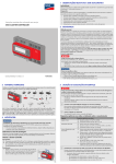
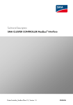
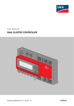
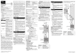
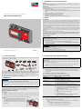
at
1 INFORMATION ON THIS DOCUMENT
Validity
This document is valid for the SMA Cluster Controller (model: CLCON-10 and CLCON-S-10) from hardware
version A1 and from firmware version 1.0.
Target Group
This document is intended for qualified persons. Only persons with the following skills are allowed to perform the
tasks set forth in this document:
• Training in the installation and commissioning of electrical devices
• Training in how to deal with the dangers and risks associated with installing and using electrical devices and
systems
• Training in the installation and configuration of IT systems
• Knowledge of how an inverter works and is operated
• Knowledge of all applicable standards and directives
• Knowledge of and compliance with this document and all safety precautions
Quick Reference Guide for Commissioning
SMA CLUSTER CONTROLLER
2 SAFETY
Intended Use
The Cluster Controller* is a device for monitoring and controlling SMA inverters with Speedwire/Webconnect interface
in decentralized PV systems and large-scale PV power plants. The Cluster Controller is an ITE class A device as per
EN 55022 and is designed for industrial use. The Cluster Controller must only be used in an indoor environment and
must only be used with supported products (for a list of the supported products, see the installation manual on the CD
included in the scope of delivery). Use this product only in accordance with the information provided in the enclosed
documentation and with the locally applicable standards and directives. Any other application may cause personal
injury or property damage.
For safety reasons, it is not permitted to modify the product or install components that are not explicitly recommended or
distributed by SMA** for the product. Unauthorized modifications and installations will void all warranty claims and the
operating permission. Any use of the product other than described in the Intended Use section does not qualify as
appropriate.
The type label must remain permanently attached to the product.
The enclosed documentation is an integral part of this product. Before installing or using the product, read and
observe all instructions, safety precautions and warning messages in this document and in the product
documentation on the enclosed CD.
Safety Precautions
%"/(&3
Danger to life due to electric shock
If overvoltage occurs (e. g. due to lightning) or if the enclosure of the Cluster Controller is not grounded, there
is a danger of electric shock.
• Ensure that the Cluster Controller is integrated in the existing lightning protection.
• Ground the enclosure of the Cluster Controller (see Section Connecting the Grounding Conductor
to the Cluster Controller).
/05*$&
ClusterController-IS-en-12 | Version 1.2
Damage to the devices and cables
The Cluster Controller is not splash water-protected (degree of protection: IP20 (NEMA 1)). Consequently, it
is possible that moisture may penetrate the device.
• Only use the Cluster Controller in a dry, indoor environment.
ENGLISH
* In this document, the SMA Cluster Controller is referred to as Cluster Controller.
** SMA = SMA Solar Technology AG, SMA America LLC, SMA Solar Technology Canada Inc.
3 SCOPE OF DELIVERY
2
5 CONNECTION AND COMMISSIONING
Check the scope of delivery for completeness and any externally visible damage. Contact your distributor if the
scope of delivery is incomplete or damaged.
A) 1 x Cluster Controller, B) 1 x three-pole plug, C) 1 x two-pole plug, D) 2 x five-pole plug, E) 8 x six-pole plug,
F) 2 x eight-pole plug, G) 2 x coding element, H) 20 x cable tie with writing field, I) 8 x shield clamp with ring
terminal lug, K) 1 x ring terminal lug, L) 1 x fastening screw, M) 2 x washer, N) 1 x tooth lock washer,
O) 1 x split lock washer, P) 1 x CD with product documentation, Q) 1 x quick reference guide for commissioning
and supplementary sheet for writing down the connected devices
%"/(&3
Danger to life due to electric shock from faulty connection of the connection cable to the ripple
control receiver
In the event of faulty connection of the connection cable to the ripple control receiver, grid voltage may be
present in the Cluster Controller enclosure.
• Do not connect insulated conductors of the connection cable to line conductors of the ripple control
receiver.
• When connecting, ensure that no bridge is being used in the ripple control receiver.
For a detailed connection description, see the installation manual
This quick reference guide enables the basic commissioning of the Cluster Controller. A detailed
description of all connection possibilities is contained in the installation manual on the CD included in the
scope of delivery.
Note down the connections on the supplementary sheet
Note down the terminal assignment on the supplementary sheet supplied.
Cable Requirements and Information on Cable Routing
Connection
4 MOUNTING
/05*$&
Radio interference in living areas possible due to the Cluster Controller
The Cluster Controller is a device of ITE class A (EN 55022) and can cause radio interference in the living
area.
• Take suitable measures for shielding radio waves when the Cluster Controller is used in the vicinity of
living areas.
Selecting the Mounting Location
Select the mounting location. Observe the mounting location requirements, the minimum clearances and the
permissible mounting position (see installation manual on the CD provided).
Mounting the Cluster Controller
Requirements:
☐ A 35 mm (1.4 in) wide top-hat rail must be available which is mounted securely on the wall or in the switch
cabinet.
☐ In order to mount the Cluster Controller, the top-hat rail must be at least 26 cm (10.3 in) in length. To mount
the top-hat rail power supply unit, the top-hat rail must be correspondingly longer.
Procedure:
• Use the rear-side upper retainers to hook the Cluster Controller into
the upper edge of the top-hat rail and press down in the direction
of the top-hat rail. This will hook the spring-mounted top-hat rail
locking mechanism of the Cluster Controller onto the lower edge of
the top-hat rail.
3
Cable requirements
Grounding
☐ Conductor cross-section: 2.5 mm2 (14 AWG)
☐ Maximum cable length: 30 cm (11 in)
Voltage supply
☐ Number of insulated conductors: at least two
☐ Conductor cross-section: 0.2 mm2 to 2.5 mm2 (32 AWG to 14 AWG)
☐ Maximum cable length: 3 m (9.8 ft)
Inverter (Speedwire) and
local area network (LAN)
☐ Number of insulated conductor pairs and insulated conductor
cross-section: at least 2 x 2 x 0.22 mm2 (at least 2 x 2 x 24 AWG)
☐ External diameter: the maximum external diameter depends on the size
of the cable gland or the conduit (see installation manual of the
Speedwire/Webconnect interface)
☐ Cable type: 100BaseTx, from CAT5 with shielding S-UTP, F-UTP or
higher
☐ Plug type: RJ45 for Cat5, Cat5e, Cat6, Cat6a
Cat7 plugs cannot be used.
☐ Cable length between two nodes: max. 50 m (164 ft) with patch
cable, max. 100 m (328 ft) with installation cable
Interference in data transmission due to unshielded energy cables
Unshielded energy cables generate an electromagnetic field during operation which may induce
interference in network cables during data transmission.
• When laying network cables, observe the following minimum clearances to unshielded energy
cables:
– For installation without separating strip: at least 200 mm (8 in)
– For installation with aluminum separating strip: at least 100 mm (4 in)
– For installation with steel separating strip: at least 50 mm (2 in)
4
Connecting the Cluster Controller to the Voltage Supply
8. Connect the connection point to the utility grid.
☑ The power LED (
) of the Cluster Controller glows red for two seconds, then it permanently glows
green. The status LED (
) glows corresponding to the current device status (see Cluster Controller
installation manual on the CD included in the scope of delivery). The Cluster Controller is ready for
operation after a maximum of one minute.
✖ Is the power LED (
) glowing permanently red, the status LED (
) glowing yellow or red and the
Cluster Controller is not starting?
Possible fault cause: the voltage supply is too low.
• Ensure that the connected voltage supply is sufficient (for requirements for the voltage supply see
the installation manual on the CD provided). If the problem persists, contact the SMA Service Line
(see Section 7).
/05*$&
Damage to the Cluster Controller due to condensation water
If the Cluster Controller is moved from a cold environment to a warm environment, condensation water may
form in the Cluster Controller.
• In the event of large temperature differences, only supply voltage to the Cluster Controller once the
Cluster Controller has reached room temperature.
Connecting the Grounding Conductor to the Cluster Controller
Additionally required material (not included in the scope of delivery):
☐ 1 grounding conductor (see Section Cable Requirements)
Checking and Setting the System Time of the Cluster Controller
Procedure:
1. Remove 10 mm (0.39 in) of the cable sheath from the grounding conductor.
2. Insert the insulated conductors into the ring terminal lug and crimp with a crimping tool.
3. Attach the grounding conductor at the terminal for grounding
(for the position of the terminal, see installation manual on the CD
included in scope of delivery). Observe the following sequence
and hand-tighten the fastening screws (torque: 0.8 Nm
(7.08 in-lb)):
– Fastening screw, split lock washer, washer, ring terminal lug
with grounding conductor, washer, tooth lock washer
Before connecting the Cluster Controller to the Speedwire network and before commissioning the inverters, you
must use the display of the Cluster Controller to check whether the correct system time is displayed on the Cluster
Controller. If the correct system time is not displayed, you must set the correct system time via the user interface of
the Cluster Controller. This avoids inconsistencies in the time settings of the inverters.
Requirement:
☐ The Cluster Controller must be connected to the voltage supply and be in operation (see Section
Connecting the Cluster Controller to the Voltage Supply).
Connecting the Power Supply Unit
Additionally required material (not included in the scope of delivery):
☐ 1 power supply unit (available as an accessory). If the power supply unit available as an accessory is not
used, observe the requirements for the power supply unit (see installation manual on the CD included in the
scope of delivery).
☐ 1 AC connection cable
☐ 1 connection cable for the connection of the power supply unit to the Cluster Controller (see Section Cable
Requirements).
Procedure:
1. Mount the power supply unit (see the manufacturer manual).
2. Connect the connection cable to the power supply unit (see the manufacturer manual). Trim the unused
insulated conductors up to the cable sheath and note down the conductor colors.
3. Connect the connection cable to the three-pole plug. Release conductor entries 2 and 3 with a screwdriver
and insert the insulated conductors into the conductor entries. Observe the pin assignment.
4. Connect the three-pole plug to terminal X1 of the Cluster Controller.
5. Connect the AC connection cable to the power supply unit (see the manufacturer manual).
6.
Procedure:
1. Use one network cable to connect the computer to the network port X13 or X14 of the Cluster Controller.
2. Log into the Cluster Controller:
• Select the display view External communication and read off the IP address of the Cluster Controller.
• Enter the IP address in the address bar of the web browser.
• Log in with the default system password (User = "0000", Installer = "1111").
3. Select the Cluster Controller in the system tree and select the Settings menu in the device menu.
4. Select the Device > Time settings parameter group.
5. Select [Edit].
6. If required, use the Standard/Daylight Saving Time conversion on drop-down list to set automatic
conversion between standard and daylight saving time.
7. In the Set PV system time field, set the current date and time of the PV system.
8. In the drop-down list Time zone, select the time zone in which the system is located.
9. Select [Save].
☑ The PV system time is updated.
10. Select [Logout] in the toolbar.
11. Connect the Cluster Controller to the Speedwire network (see Section Connecting the Cluster Controller
to a Speedwire Network) and make any additional required connections.
%"/(&3
Danger to life due to electric shock
Lethal voltages are present at the connection point of the utility grid.
• Disconnect the connection point from voltage sources and ensure that the connection point is
voltage-free.
7. Connect the other end of the AC connection cable to the voltage supply.
5
Connecting the Cluster Controller to a Speedwire Network
6
Connecting USB Data Carriers to the Cluster Controller
Do not connect the Speedwire network and the local area network (LAN)
The Speedwire network is a separate network managed by the Cluster Controller. If the Speedwire
network and the local area network (LAN) are connected, a disturbance of both networks is likely to
occur.
• In order to ensure correct communication, do not connect the Speedwire network and the local
area network (LAN). The Speedwire bus and the Ethernet bus must not be connected to the same
switch.
Not possible to use USB hubs
The Cluster Controller does not support any USB hubs. You must connect the USB data carrier directly
to the desired USB terminal on the Cluster Controller.
Additionally required material (not included in the scope of delivery):
Observe the configuration of the router and the network switch
Procedure:
☐
1.
For the Speedwire connection, the Cluster Controller uses IP addresses from the Unicast area and also
IP addresses from the Multicast area 239/8 (239.0.0.0 to 239.255.255.255).
• When using a router or network switch, ensure that the router and switch forward the Multicast
telegrams required for the Speedwire connection to all nodes of the Speedwire network
(for information on configuration of the router or switch, see the manufacturer manual).
2.
Requirements:
☐ The nodes in the Speedwire network (e. g. inverters) must be cabled in accordance with one of the possible
network topologies (see the node installation manual and the Technical Information "SMA Speedwire
Fieldbus").
Additionally required material (not included in the scope of delivery):
☐ Depending on the network topology: network cable (see Section Cable Requirements).
Up to two USB data carriers, e.g. two USB sticks (available as an accessory). If the USB data carrier available as
an accessory is not used, observe the requirements for USB data carriers (see installation manual on the CD
included in the scope of delivery).
Connect the USB data carrier to the desired USB terminal of the Cluster Controller.
• To export system data, connect the USB data carrier to the USB terminal 1.
• To transmit update files to the Cluster Controller, connect the USB data carrier to USB terminal 2.
If the USB data carrier is to be removed from the Cluster Controller, wait until the data carrier status LED (
not flashing anymore.
) is
Checking the Connections via the Display
•
You can use the display of the Cluster Controller to check whether the connections have been made correctly and
whether all inverters, sensors and remote terminals have been recorded by the
Cluster Controller (see installation manual on the CD included in the scope of delivery).
6 CONFIGURING THE CLUSTER CONTROLLER
Requirement:
Procedure:
• Connect the network cable to the network port X9 or X10 of the Cluster Controller.
☐
The Cluster Controller and the computer must be located in the same local area network (LAN).
Procedure:
1. Log into the Cluster Controller:
Connecting the Cluster Controller to the Local Area Network
/05*$&
High costs possible through inappropriate Internet rates
Depending on use, the data volume of the Cluster Controller transferred via the Internet can be more than 1
GB per month. The data volume depends, among other things, on the number of inverters, the frequency of
device updates, the frequency of data transfer to the Sunny Portal and the use of FTP push.
• SMA recommends using an Internet flat rate.
2.
3.
• Select the External Communication display view and read out the IP address of the Cluster Controller.
• Enter the IP address in the address bar of the web browser.
• Log in with the default system password (User = "0000", Installer = "1111").
Deactivate the Webconnect function of the inverters (see user manual of the Cluster Controller on the CD included
in the scope of delivery).
Make further desired configurations via the user interface (see user manual on the CD included in the scope of
delivery).
7 CONTACT
Different IP address ranges required for Speedwire network and local network (LAN)
If you have technical problems with our products, contact the SMA Service Line. We require the following information
in order to provide you with the necessary assistance:
• Serial number and firmware version of the Cluster Controller
• Type, serial number, and firmware version of the inverter
• When using a retrofitted Speedwire/Webconnect interface:
Serial number and firmware version of the Speedwire/Webconnect interface
In order to clearly assign the IP addresses in the Speedwire network and in the local network (LAN) from
the perspective of the Cluster Controller to be possible, the IP address ranges of both networks must be
different. By default, the Cluster Controller uses address range 172.22/16 (172.22.0.1 to
172.22.255.255) for the Speedwire network.
• Make sure that different IP address ranges are used for the Speedwire network and the local
network (LAN).
SMA Solar Technology AG
Niestetal, Germany
International SMA Service Line
Toll free worldwide: 00800 SMA SERVICE
(+800 762 7378423)
Additionally required material (not included in the scope of delivery):
☐ 1 network cable (see Section Cable Requirements)
Procedure:
1. Connect the network cable to the network port X13 or X14 of the Cluster Controller.
2. Connect the other end of the patch cable to the desired device in the local area network (LAN).
7
SMA America, LLC
Rocklin, CA, United States/Estados Unidos
+1 877-MY-SMATech (+1 877-697-6283)*
+1 916 625-0870**
SMA Canada, Inc.
Toronto, Canada/Canadá
+1 877-MY-SMATech (+1 877-697-6283)***
* toll free for USA, Canada and Puerto Rico / Llamada gratuita en EE. UU., Canadá y Puerto Rico
** international / internacional
*** toll free for Canada / gratuit pour le Canada
8