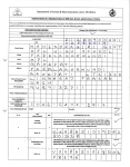
1
Powered by Eaton’s
Cutler-Hammer Technology
N2 and XT BUS Communication
User Manual
March 2006
Supersedes January 2006
VSD IntelliPass
Code No. LIT-1201829
VSD Open
For more information visit: www.johnsoncontrols.com
VSD Enclosed Intellipass w/DX-9100
Powered by Eaton’s
Cutler-Hammer Technology
N2 and XT BUS Communication User Manual
March 2006
Important Notice – Please Read
The product discussed in this literature is subject to terms and conditions outlined in
Johnson Controls selling policies. The sole source governing the rights and remedies of any
purchaser of this equipment is the relevant Johnson Controls selling policy.
NO WARRANTIES, EXPRESS OR IMPLIED, INCLUDING WARRANTIES OF FITNESS FOR A
PARTICULAR PURPOSE OR MERCHANTABILITY, OR WARRANTIES ARISING FROM COURSE
OF DEALING OR USAGE OF TRADE, ARE MADE REGARDING THE INFORMATION,
RECOMMENDATIONS AND DESCRIPTIONS CONTAINED HEREIN. In no event will Johnson
Controls or Eaton Electrical Inc. be responsible to the purchaser or user in contract, in tort
(including negligence), strict liability or otherwise for any special, indirect, incidental or
consequential damage or loss whatsoever, including but not limited to damage or loss of use of
equipment, plant or power system, cost of capital, loss of power, additional expenses in the use
of existing power facilities, or claims against the purchaser or user by its customers resulting
from the use of the information, recommendations and descriptions contained herein.
The information contained in this manual is subject to change without notice.
Cover Photo: Johnson Controls VSD Series Drives.
Code No. LIT-1201829
For more information visit: www.johnsoncontrols.com
i
N2 and XT BUS Communication User Manual
Powered by Eaton’s
Cutler-Hammer Technology
March 2006
Table of Contents
LIST OF FIGURES . . . . . . . . . . . . . . . . . . . . . . . . . . . . . . . . . . . . . . . . . . . . . . . . . . . . . . .
LIST OF TABLES . . . . . . . . . . . . . . . . . . . . . . . . . . . . . . . . . . . . . . . . . . . . . . . . . . . . . . . .
SAFETY . . . . . . . . . . . . . . . . . . . . . . . . . . . . . . . . . . . . . . . . . . . . . . . . . . . . . . . . . . . . . . .
Definitions and Symbols . . . . . . . . . . . . . . . . . . . . . . . . . . . . . . . . . . . . . . . . . . . . .
Hazardous High Voltage . . . . . . . . . . . . . . . . . . . . . . . . . . . . . . . . . . . . . . . . . . . . .
iii
iii
iv
iv
iv
CHAPTER 1 — OVERVIEW . . . . . . . . . . . . . . . . . . . . . . . . . . . . . . . . . . . . . . . . . . . . . . . 1-1
Introduction . . . . . . . . . . . . . . . . . . . . . . . . . . . . . . . . . . . . . . . . . . . . . . . . . . . . . . . 1-1
Specifications . . . . . . . . . . . . . . . . . . . . . . . . . . . . . . . . . . . . . . . . . . . . . . . . . . . . . . 1-1
CHAPTER 2 — BOARD LAYOUT AND CONNECTIONS . . . . . . . . . . . . . . . . . . . . . . . . 2-1
VS-OPTNX Communication Board . . . . . . . . . . . . . . . . . . . . . . . . . . . . . . . . . . . . 2-1
CHAPTER 3 — INSTALLATION . . . . . . . . . . . . . . . . . . . . . . . . . . . . . . . . . . . . . . . . . . . .
Making the Ground Connection . . . . . . . . . . . . . . . . . . . . . . . . . . . . . . . . . . . . . . .
Bus Terminal Resistors . . . . . . . . . . . . . . . . . . . . . . . . . . . . . . . . . . . . . . . . . . . . . .
LED Indications. . . . . . . . . . . . . . . . . . . . . . . . . . . . . . . . . . . . . . . . . . . . . . . . . . . . .
Installing the VS-OPTNX Communication Board . . . . . . . . . . . . . . . . . . . . . . . . .
3-1
3-1
3-3
3-4
3-5
CHAPTER 4 — COMMISSIONING . . . . . . . . . . . . . . . . . . . . . . . . . . . . . . . . . . . . . . . . . . 4-1
Fieldbus Board Parameters . . . . . . . . . . . . . . . . . . . . . . . . . . . . . . . . . . . . . . . . . . . 4-1
RS-485 Communication Parameters. . . . . . . . . . . . . . . . . . . . . . . . . . . . . . . . . . . . 4-1
CHAPTER 5 — JOHNSON CONTROLS METASYS N2 PROTOCOL . . . . . . . . . . . . . . . 5-1
Overview . . . . . . . . . . . . . . . . . . . . . . . . . . . . . . . . . . . . . . . . . . . . . . . . . . . . . . . . . . 5-1
N2 Point Map . . . . . . . . . . . . . . . . . . . . . . . . . . . . . . . . . . . . . . . . . . . . . . . . . . . . . . 5-3
CHAPTER 6 — JOHNSON CONTROLS METASYS XT BUS PROTOCOL . . . . . . . . . . . 6-1
DX-9100 XT Bus . . . . . . . . . . . . . . . . . . . . . . . . . . . . . . . . . . . . . . . . . . . . . . . . . . . . 6-1
XT Bus Point Map. . . . . . . . . . . . . . . . . . . . . . . . . . . . . . . . . . . . . . . . . . . . . . . . . . . 6-8
CHAPTER 7 — COMMUNICATION BOARD FAULT TRACKING . . . . . . . . . . . . . . . . . . 7-1
APPENDIX A — PROCESS DATA . . . . . . . . . . . . . . . . . . . . . . . . . . . . . . . . . . . . . . . . . . A-1
Process Data OUT (Slave ➔ Master). . . . . . . . . . . . . . . . . . . . . . . . . . . . . . . . . . . . A-1
ii
For more information visit: www.johnsoncontrols.com
Code No. LIT-1201829
Powered by Eaton’s
Cutler-Hammer Technology
N2 and XT BUS Communication User Manual
March 2006
List of Figures
Figure 2-1: Option Board VS-OPTNX Communication Board . . . . . . . . . . . . . . . . . . . . . .
Figure 3-1: Cable Stripping . . . . . . . . . . . . . . . . . . . . . . . . . . . . . . . . . . . . . . . . . . . . . . . . . .
Figure 3-2: Inserting the Data Cables . . . . . . . . . . . . . . . . . . . . . . . . . . . . . . . . . . . . . . . . .
Figure 3-3: Grounding the Communication Cable . . . . . . . . . . . . . . . . . . . . . . . . . . . . . . .
Figure 3-4: Stripping the Communication Cables . . . . . . . . . . . . . . . . . . . . . . . . . . . . . . .
Figure 3-5: Grounding the Communication Cable . . . . . . . . . . . . . . . . . . . . . . . . . . . . . . .
Figure 3-6: Using Jumper X4 to Set the Bus Termination . . . . . . . . . . . . . . . . . . . . . . . . .
Figure 3-7: LED Indications on the Communication Board . . . . . . . . . . . . . . . . . . . . . . . .
Figure 4-1: Communication Status . . . . . . . . . . . . . . . . . . . . . . . . . . . . . . . . . . . . . . . . . . .
Figure 6-1: Define VSD Analog Points by Selecting the 6AI,
2AO XT Module . . . . . . . . . . . . . . . . . . . . . . . . . . . . . . . . . . . . . . . . . . . . . . . . . . . . . . .
Figure 6-2: Assign User Names and the Hardware Address for
the XT Module . . . . . . . . . . . . . . . . . . . . . . . . . . . . . . . . . . . . . . . . . . . . . . . . . . . . . . . .
Figure 6-3: Define VSD Digital Points by Selecting the 4DI,
4DO XT Expansion Module . . . . . . . . . . . . . . . . . . . . . . . . . . . . . . . . . . . . . . . . . . . . . .
Figure 6-4: Assign User Names for the XT Expansion Module . . . . . . . . . . . . . . . . . . . . .
Figure 6-5: Define All of the VSD/XT Analog Inputs as “Active” . . . . . . . . . . . . . . . . . . .
Figure 6-6: Define the VSD/XT Active Analog Inputs as Noted in Table 6-1 . . . . . . . . . . .
Figure 6-7: Define the VSD/XT Digital Inputs as Noted in Table 6-3 . . . . . . . . . . . . . . . . .
Figure 6-8: Assign User Names and Define the VSD/XT Analog Outputs
as Noted in Table 6-2 . . . . . . . . . . . . . . . . . . . . . . . . . . . . . . . . . . . . . . . . . . . . . . . . . . .
Figure 6-9: Define the VSD/XT Digital Outputs as ON/OFF Type . . . . . . . . . . . . . . . . . . .
Figure 6-10: Assign User Names for the VSD/XT Digital Outputs
as Noted in Table 6-4 . . . . . . . . . . . . . . . . . . . . . . . . . . . . . . . . . . . . . . . . . . . . . . . . . . .
Figure 6-11: After Saving the File — Download the DX and XT from
the “Action” Menu . . . . . . . . . . . . . . . . . . . . . . . . . . . . . . . . . . . . . . . . . . . . . . . . . . . . .
2-1
3-1
3-1
3-2
3-2
3-3
3-3
3-4
4-3
6-2
6-2
6-3
6-3
6-4
6-4
6-5
6-5
6-6
6-6
6-7
List of Tables
Table 1-1: Specifications . . . . . . . . . . . . . . . . . . . . . . . . . . . . . . . . . . . . . . . . . . . . . . . . . . . .
Table 2-1: VS-OPTNX Bus Connector Signals . . . . . . . . . . . . . . . . . . . . . . . . . . . . . . . . . . .
Table 3-1: Communication Board Status LED (BS) — YELLOW . . . . . . . . . . . . . . . . . . . .
Table 3-2: Fieldbus Status LED (FS) — GREEN . . . . . . . . . . . . . . . . . . . . . . . . . . . . . . . . . .
Table 3-3: Installing the VS-OPTNX Communication Board . . . . . . . . . . . . . . . . . . . . . . .
Table 4-1: Changing the N2/XT Bus Board Commissioning Parameter Values . . . . . . . .
Table 4-2: Communication Message Indications . . . . . . . . . . . . . . . . . . . . . . . . . . . . . . . .
Table 5-1: Analog Inputs (AI) . . . . . . . . . . . . . . . . . . . . . . . . . . . . . . . . . . . . . . . . . . . . . . . .
Table 5-2: Binary Inputs (BI) . . . . . . . . . . . . . . . . . . . . . . . . . . . . . . . . . . . . . . . . . . . . . . . . .
Table 5-3: Analog Outputs (AO) . . . . . . . . . . . . . . . . . . . . . . . . . . . . . . . . . . . . . . . . . . . . . .
Table 5-4: Binary Outputs (BO) . . . . . . . . . . . . . . . . . . . . . . . . . . . . . . . . . . . . . . . . . . . . . . .
Table 5-5: Internal Integers (ADI) . . . . . . . . . . . . . . . . . . . . . . . . . . . . . . . . . . . . . . . . . . . . .
Table 6-1: Analog Inputs (AI) . . . . . . . . . . . . . . . . . . . . . . . . . . . . . . . . . . . . . . . . . . . . . . . .
Table 6-2: Analog Outputs (AO) . . . . . . . . . . . . . . . . . . . . . . . . . . . . . . . . . . . . . . . . . . . . . .
Table 6-3: Digital Inputs (DI) . . . . . . . . . . . . . . . . . . . . . . . . . . . . . . . . . . . . . . . . . . . . . . . . .
Table 6-4: Digital Outputs (DO) . . . . . . . . . . . . . . . . . . . . . . . . . . . . . . . . . . . . . . . . . . . . . . .
Table 7-1: Communication Board Faults . . . . . . . . . . . . . . . . . . . . . . . . . . . . . . . . . . . . . . .
Table 7-2: VSD Response to Faults . . . . . . . . . . . . . . . . . . . . . . . . . . . . . . . . . . . . . . . . . . .
Table A-1: Fieldbus Parameters — M1 ➔ G1.9 . . . . . . . . . . . . . . . . . . . . . . . . . . . . . . . . . .
Code No. LIT-1201829
For more information visit: www.johnsoncontrols.com
1-1
2-1
3-4
3-4
3-5
4-1
4-3
5-3
5-4
5-4
5-5
5-5
6-8
6-8
6-8
6-8
7-1
7-1
A-1
iii
N2 and XT BUS Communication User Manual
Powered by Eaton’s
Cutler-Hammer Technology
March 2006
Safety
Definitions and Symbols
WARNING
This symbol indicates high voltage. It calls your attention to items
or operations that could be dangerous to you and other persons
operating this equipment. Read the message and follow the
instructions carefully.
This symbol is the “Safety Alert Symbol.” It occurs with either of
two signal words: CAUTION or WARNING, as described below.
WARNING
Indicates a potentially hazardous situation which, if not avoided,
can result in serious injury or death.
CAUTION
Indicates a potentially hazardous situation which, if not avoided,
can result in minor to moderate injury, or serious damage to the
product. The situation described in the CAUTION may, if not
avoided, lead to serious results. Important safety measures are
described in CAUTION (as well as WARNING).
Hazardous High Voltage
WARNING
Motor control equipment and electronic controllers are connected
to hazardous line voltages. When servicing drives and electronic
controllers, there may be exposed components with housings or
protrusions at or above line potential. Extreme care should be taken
to protect against shock.
Stand on an insulating pad and make it a habit to use only one
hand when checking components. Always work with another
person in case an emergency occurs. Disconnect power before
checking controllers or performing maintenance. Be sure
equipment is properly grounded. Wear safety glasses whenever
working on electronic controllers or rotating machinery.
iv
For more information visit: www.johnsoncontrols.com
Code No. LIT-1201829
Powered by Eaton’s
Cutler-Hammer Technology
N2 and XT BUS Communication User Manual
March 2006
Chapter 1 — Overview
Introduction
The Johnson Controls VSD Series Drives powered by Cutler-Hammer® technology from
Eaton’s electrical business can be controlled, monitored and programmed from a host
system via Johnson Controls N2 or XT BUS communication protocols with the addition of
the VS-OPTNX RS-485 Communication Option Board.
If you purchase your Communication Board separate from the drive, please note that it must
be installed in slot D or E on the control board of the VSD Series drive.
Specifications
Table 1-1: Specifications
Item
Specification
Communication Board Connections
Interface
VS-OPTNX: Pluggable connector (5.08 mm)
Data Transfer Method
RS-485, half-duplex
Communication Bus
3-wire (Twisted pair + Reference) shield optional Electrical Isolation
500V DC
Communications
Johnson Controls N2 Bus
As described in Metasys N2 System Protocol Specification
Johnson Controls XT Bus
As described in Metasys System 9100 Protocol Specification
Baud Rate
9600 baud
Addresses
1 to 247
Environment
Ambient Operating Temperature
14 to 131°F (-10 to 55°C)
Storage Temperature
-40 to 140°F (-40 to 60°C)
Humidity
<95%, non-condensing
Altitude
Max. 3280 ft. (1000m)
Vibration
0.5G at 9 to 200 Hz
Safety
Standards
Fulfils EN 50178 standard
Certification
CE, UL
Code No. LIT-1201829
The N2/XT Bus is a “daisy chain” communications line. It consists of three wires for the following signals: +, –, and Common. The
+ and – lines carry the actual data signals. The Common line provides a reference so that each connected device is capable of electrically receiving and transmitting data by creating a common voltage reference among all the devices connected together over
the communication bus. Three conductors are required. It is important that the + and – lines are twisted together, which allows
most induced noise (common-mode noise) from external sources to affect both lines equally, thereby canceling the noise. In most
installations, the communication bus works fine with unshielded cable. However, in noisy environments, shielded twisted wire
must be used.
For more information visit: www.johnsoncontrols.com
1-1
N2 and XT BUS Communication User Manual
Powered by Eaton’s
Cutler-Hammer Technology
March 2006
1-2
For more information visit: www.johnsoncontrols.com
Code No. LIT-1201829
Powered by Eaton’s
Cutler-Hammer Technology
N2 and XT BUS Communication User Manual
March 2006
Chapter 2 — Board Layout and Connections
The VS-OPTNX RS-485 Communication Board is connected to the communications bus
through a 5-pin pluggable bus connector.
Communication with the control board of the drive takes place through the standard Interface
Board Connector (see Figure 2-1).
VS-OPTNX Communication Board
Yellow = RS-485 Board Status
Green = Field Bus Status
1
2
3
4
5
X4
X1
Bus Connector
Jumpers
Interface Board Connector
Figure 2-1: Option Board VS-OPTNX Communication Board
Table 2-1: VS-OPTNX Bus Connector Signals
Signal
Connector
Description
SHLD 1
Shield
VP
2
Supply voltage – plus 5V (not used)
-
3
Receive/Transmit data – minus (N2-/RT-)
+
4
Receive/Transmit data – plus (N2+/RT+)
COM
5
Bus Common (REF/COM)
This pin (1) can be used to bypass the cable shield to the next slave.
ON
X4 jumper is the 120Ω termination resistor. Set X4 jumper to ON only if the
Johnson Controls N2 Protocol is selected and the drive is the last device on the
network. N/A for XT bus communication.
X1 jumper has no effect on VS-OPTNX board.
OFF
Code No. LIT-1201829
For more information visit: www.johnsoncontrols.com
2-1
N2 and XT BUS Communication User Manual
Powered by Eaton’s
Cutler-Hammer Technology
March 2006
2-2
For more information visit: www.johnsoncontrols.com
Code No. LIT-1201829
Powered by Eaton’s
N2 and XT BUS Communication User Manual
Cutler-Hammer Technology
March 2006
Chapter 3 — Installation
Making the Communication Bus and Ground Connections
Terminating the Ground Wire
Note: Normally, the option board has already been installed in slot D or E of the control
board. It is not necessary to detach the whole board to connect the communication bus
and ground the bus cable shield. Just detach the terminal block.
1. Strip about 2 in. (5 cm) of the communication cable and cut off the gray cable shield.
Remember to do this for both bus cables (except for the last device). See Figure 3-1.
2. Strip the individual conductors at about 0.2 in (0.5 cm) to fit in the terminals. See Figure
3-1.
Figure 3-1: Cable Stripping
3. Insert the data cables into terminals #3 (-), #4 (+) and #5 (Com.).
1 2 3 4 5
To next
N2/XT Bus
Device
-
+
Com.
From
Previous
N2/XT Bus
Device
Figure 3-2: Inserting the Data Cables
Code No. LIT-1201829
For more information visit: www.johnsoncontrols.com
3-1
N2 and XT BUS Communication User Manual
Powered by Eaton’s
Cutler-Hammer Technology
March 2006
Grounding by Clamping the Cable to the Converter Frame
This method of grounding is the most effective, and especially recommended when the
distances between the devices are relatively short.
Strip the communication cable so that it can be secured to the drive frame with the
grounding clamp.
Figure 3-3: Grounding the Communication Cable
Grounding Only One Point on the Net
In this method of grounding, the shield is connected to ground only at the last device on the
network. Other devices on the network just bypass the shield.
1. Strip about 2 in. (5 cm) of the communication cable and cut off the gray cable shield.
2. Leave no more than 1/4 in. (1 cm) of the cable outside the terminal block and strip the
data cables at about 0.5 cm to fit in the terminals. See Figure 3-4.
1 2 3 4 5
Shield
-
Com.
+
Figure 3-4: Stripping the Communication Cables
3-2
For more information visit: www.johnsoncontrols.com
Code No. LIT-1201829
Powered by Eaton’s
Cutler-Hammer Technology
N2 and XT BUS Communication User Manual
March 2006
3. Secure the communication cable to the drive frame with the grounding clamp as shown
in Figure 3-5.
Figure 3-5: Grounding the Communication Cable
Bus Terminal Resistors
If the VS-OPTNX Option Card is programmed for N2 communication and it is the last device
on the network, the bus termination must be set to ON. Use jumper X4 (set to the ON
position for termination). See Figure 3-6.
ON = Terminated: This is the last device on N2 bus network.
OFF = Not Terminated: At least one other N2 bus network
device is connected past this device.
1
2
3
4
5
X4
X1
Bus Connector
Jumpers
Interface Board Connector
Figure 3-6: Using Jumper X4 to Set the Bus Termination
Code No. LIT-1201829
For more information visit: www.johnsoncontrols.com
3-3
N2 and XT BUS Communication User Manual
Powered by Eaton’s
Cutler-Hammer Technology
March 2006
LED Indications
The two LED indicators next to the connector show the present status of the Communication
Board (yellow) and the Fieldbus Module (green).
Yellow = RS-485 Board Status
Green = Fieldbus Status
Yellow
Green
1
2
3
4
5
X4
X1
Figure 3-7: LED Indications on the Communication Board
Table 3-1: Communication Board Status LED (BS) — YELLOW
LED is:
Meaning:
OFF
Option board not activated
ON
Option board in initialization state waiting for activation command from
the Variable Speed Drive (VSD)
Blinking fast (once/sec)
Option board is activated and in RUN state
Option board is ready for external communication
Blinking slow (once/5 secs)
Option board is activated and in FAULT state
Internal fault of option board
Table 3-2: Fieldbus Status LED (FS) — GREEN
3-4
LED is:
Meaning:
OFF
Fieldbus module is waiting for parameters from the VSD
No external communication
ON
Fieldbus module is activated
Parameters received and module activated
Module is waiting for messages from the bus
Blinking fast (once/sec)
Module is activated and receiving messages from the bus
Blinking slow (once/5 secs)
Module is in FAULT state
No messages from Master within the watchdog time
Bus broken, cable loose or Master off-line
For more information visit: www.johnsoncontrols.com
Code No. LIT-1201829
Powered by Eaton’s
Cutler-Hammer Technology
N2 and XT BUS Communication User Manual
March 2006
Installing the VS-OPTNX Communication Board
Table 3-3: Installing the VS-OPTNX Communication Board
Procedure
Illustration
1. Remove the cable cover.
2. Open the cover of the control unit.
3. Install the VS-OPTNXC2 option board in slot D or E on the
control board of the VSD. Make sure that the grounding
plate (see below) fits tightly in the clamp.
1
2
3
4
5
X4
X1
Grounding Plate
Code No. LIT-1201829
For more information visit: www.johnsoncontrols.com
3-5
N2 and XT BUS Communication User Manual
Powered by Eaton’s
Cutler-Hammer Technology
March 2006
Table 3-3: Installing the VS-OPTNX Communication Board, continued
Procedure
Illustration
4. Make a sufficiently wide opening for your cable by cutting
the cover grid as wide as necessary.
5. Close the cover of the control unit and the cable cover.
3-6
For more information visit: www.johnsoncontrols.com
Code No. LIT-1201829
Powered by Eaton’s
N2 and XT BUS Communication User Manual
Cutler-Hammer Technology
March 2006
Chapter 4 — Commissioning
Fieldbus Board Parameters
The VS-OPTNX RS-485 Communication board is commissioned with the control keypad by
selecting values for the appropriate parameters in the Expander board menu M6.
Expander Board Menu (M6)
The Expander board menu makes it possible for the user, (1) to see what expander boards
are connected to the control board and (2) to view and edit the parameters associated with
the expander board. See the step-by-step procedure to commission the RS-485
communication board below.
RS-485 Communication Parameters
Table 4-1: Changing the N2/XT Bus Board Commissioning Parameter Values
#
Name
Default
Range
Description
1
Communication
Protocol
1
1 – N2 Bus
2 – XT Bus
3 – SA Bus
Metasys N2 bus communication
Metasys DX-9100 XT bus communication
Metasys MS/TP BACnet Communications
(future)
2
Slave Address
1
1…247
3
Communication
Timeout
10
0 – OFF
1 – 300 s
See Communication Timeout on Page 4-2
The parameters of every device must be set before connecting to the bus. The parameter
“SLAVE ADDRESS” must be the same as programmed in the master configuration. (N2
Supervisory System or DX 9100 device.)
Perform the Following Steps to Commission the RS-485 Communication Board
●
From Operate Menu
●
Programing Press
to
●
to M6 (Expander boards / G1-G5)
●
to G6.4 (D:OPTCC / G1-G2)
or G6.5 (E:OPTCC / G1-G2)
●
G6.4.1 (Parameters P1-P3)
or G6.5.1 (Parameters P1-P3)
●
P6.4.1.1 or P6.5.1.1 (Comm. Protocol)
N2
, or
XT
Note: If… G6.4 (Slot D: or E: = OPTC2) and P6.4.1.1 or P6.5.1.1 (Comm. Protocol)
ModBus, or
N2, the RS-485 card in the drive is the VS-OPTC2 comm. card not the
VS-OPTNX comm. card. The RS-485 comm. card can be reprogrammed with the VSOPTNX firmware using the 9000X Load software available on the Johnson Controls
Portal (or the Exchange website). See the notes on Page 4-2 or contact JCI Field
Support Center for further information.
●
P6.4.1.2 or P6.5.1.2 (Slave Address)
●
P6.4.1.3 or P6.5.1.3 (Comm. Timeout)
●
●
Code No. LIT-1201829
1 to 247
0 to 10 seconds
To Main Menu
to M8 (Operate Mode Press
)
For more information visit: www.johnsoncontrols.com
4-1
N2 and XT BUS Communication User Manual
Powered by Eaton’s
Cutler-Hammer Technology
March 2006
Procedure to Check the RS-485 Communication Software Revision
●
From Operate Menu
●
Programing Press
to
●
to M5 (System Menu / S1 – S11)
●
to S5.8 (System Info / I1 – 17)
●
to S5.8.6 (Expander boards / E1 – E5)
●
to E5.8.6.4 (D:OPTCC / E1 – E2)
●
to E5.8.6.4.2 (Program version), or E5.8.6.5.2 (Program version)
or E5.8.6.5 (E:OPTCC / E1 – E2)
10610.6 = VS-OPTNX software (N2/XT) standard for VSD Series drives (No further action
needed).
If the comm. card revision displays …
10605.3 = VS-OPTC2 (pre-release software N2/XT) or …
10514.15 = VS-OPTC2 software (ModBus/N2) standard for Eaton drives (Perform the
following steps)
!
IMPORTANT
The RS-485 card must be in option card slot E when running the
C2toCC.exe program.
1. Run the executable file “C2toCC.exe” that is required to convert the ID of the RS-485
card so the drive will recognize the comm. card as the VS-OPTNX.
2. Download the System Software (SVX00031V015.vcn).
3. Download the JCI Application Wizard software (JCX0001V215.vcn).
4. Download the RS-485 communication card with the N2/XT protocol file (NXOPTC2_
10610V006.vcn).
Following these 5-steps will insure your drive is operating with the latest software revisions.
Note: Skip Steps 2 and 4 if the VSD Series Drive order was placed on/after January 13, 2006.
Communication Timeout
The RS-485 communication board initiates a communication error if communication is
broken for as long as defined by Communication Timeout. Communication Timeout is
disabled when given the value 0.
4-2
For more information visit: www.johnsoncontrols.com
Code No. LIT-1201829
Powered by Eaton’s
Cutler-Hammer Technology
N2 and XT BUS Communication User Manual
March 2006
Communication Status
To see the present status of the communication board, enter the Communication status page
from the Monitor menu (G6.4.2). See Figure 4-1 and Table 4-2.
Monitor
V1
Comm. status
V1
0.841
Good Message Count
Error Message Count
Figure 4-1: Communication Status
Table 4-2: Communication Message Indications
Messages
Indications
Good messages
0 – 999
Number of messages received without communication errors
Error messages
0 – 64
Code No. LIT-1201829
Number of messages received with CRC or parity errors
For more information visit: www.johnsoncontrols.com
4-3
N2 and XT BUS Communication User Manual
Powered by Eaton’s
Cutler-Hammer Technology
March 2006
4-4
For more information visit: www.johnsoncontrols.com
Code No. LIT-1201829
Powered by Eaton’s
Cutler-Hammer Technology
N2 and XT BUS Communication User Manual
March 2006
Chapter 5 — Johnson Controls Metasys N2 Protocol
Overview
The N2 Interface provides:
●
Direct control of Drive (e.g. Run, Stop, Direction, Speed reference, Fault reset)
●
Full access to necessary parameters
●
Monitoring of Drive status (e.g. Output frequency, Output current, Fault code)
●
In stand-alone operation, or if the polling is stopped, the overridden values are released
after 10 minutes.
Analog Input (AI) Features
All Analog Input (AI) points have the following features:
●
Support Change of State (COS) reporting based on high and low warning limits.
●
Support Change of State (COS) reporting based on high and low alarm limits.
●
Support Change of State (COS) reporting based on override status.
●
Always considered reliable and never out of range.
●
Writing of alarm and warning limit values beyond the range that can be held by the
drive’s internal variable will result in having that limit replaced by the “Invalid Float”
value even though the message is acknowledged. The net result will be the inactivation
of the alarm or warning (the same as if the original out of range value was used).
●
The N2 system should be set up to disallow overriding AI points or have an alarm
condition activated when a AI point is overridden. Overriding is supported from the
standpoint that the “Override Active” bit will be set and the value reported to the N2
network will be the overridden value. However, the value in the drive remains
unchanged.
●
Overriding an AI point with a value beyond the limit allowed by the drive’s internal
variable will result in an “Invalid Data” error response and the override status and
value will remain unchanged.
Binary Input (BI) Features
All Binary Input (BI) points have the following features:
●
Support Change of State (COS) reporting based on current state.
●
Support Change of State (COS) reporting based on alarm condition.
●
Support Change of State (COS) reporting based on override status.
●
Always considered reliable.
The N2 system should be set up to disallow overriding BI points or have an alarm condition
activated when a BI point is overridden. Overriding is supported from the standpoint that the
“Override Active” bit will be set and the value reported to the N2 network will be the
overridden value. However, the value in the drive remains unchanged.
Code No. LIT-1201829
For more information visit: www.johnsoncontrols.com
5-1
N2 and XT BUS Communication User Manual
Powered by Eaton’s
Cutler-Hammer Technology
March 2006
Analog Output (AO) Features
All Analog Output (AO) points have the following features:
●
Support Change of State (COS) reporting based on override status.
●
Always considered reliable.
●
Overriding of the AO points is the method used to change a value. Overriding an AO
point with a value beyond the limit allowed by the drive’s internal variable will result in
an “Invalid Data” error response and the override status and value will remain
unchanged. If the overridden value is beyond the drive’s parameter limit but within the
range that will fit in the variable, an acknowledge response is given and the value will
be internally clamped to its limit.
●
An AO point override copies the override value to the corresponding drive parameter.
This is the same as changing the value on the drive keypad. The value is nonvolatile
and will remain in effect when the drive is turned off and back on. It also remains at this
value when the N2 network “Releases” the point. The N2 system always reads the
current parameter value.
Note: The N2 system will not poll the AO point when it is being overridden. In this case, the
N2 system will not notice a change in value if the change is made via the keypad. To
avoid this scenario, set the point up as a “local control” type and release it once it has
been overridden. In this way, the N2 system will monitor the value when not being
overridden.
Binary Output (BO) Features
All Binary Output (BO) points have the following features:
●
Support Change of State (COS) reporting based on override status.
●
Always considered reliable.
●
Overriding BO points control the drive. These points are inputs commands to the drive.
When released, the drive’s internal value remains at its last overridden value.
Internal Integer (ADI) Features
All Internal Integer (ADI) points have the following features:
5-2
●
Do not support Change of State (COS) reporting.
●
Can not be overridden.
For more information visit: www.johnsoncontrols.com
Code No. LIT-1201829
Powered by Eaton’s
Cutler-Hammer Technology
N2 and XT BUS Communication User Manual
March 2006
N2 Point Map
Analog Input (AI) Point Map
Table 5-1: Analog Inputs (AI)
NPT
NPA
Description
Units
Note
AI
1
Speed Setpoint
Hz
2 decimals
AI
2
Output Speed
Hz
2 decimals
AI
3
Motor Speed
Rpm
0 decimal
AI
4
Load (power)
%
1 decimal
AI
5
Megawatt Hours
MWh
Total Counter
AI
6
Motor Current
A
2 decimal
AI
7
Bus Voltage
V
0 decimal
AI
8
Motor Volts
V
1 decimal
AI
9
Heatsink Temperature
°C
0 decimal
AI
10
Motor Torque
%
1 decimal
AI
11
Operating Days
Day
0 decimal
AI
12
Operating Hours
Hour
0 decimal
AI
13
Kilowatt Hours
kWh
Trip Counter
AI
14
Torque Reference
%
1 decimal
AI
15
Motor Temperature Rise
%
1 decimal
AI
16
PID Feedback (Process Variable)
(Dependent on PID Application)
" wc/Pa
" wc/Pa
psi/kPa
°F/°C
%
— Duct Static
— Building Static
— Pressure
— Temperature
— Generic
AI
17
Open (future use)
—
—
AI
18
FBDataOut1Sel —
0 decimal
AI
19
FBDataOut2Sel —
0 decimal
20
FBDataOut3Sel
—
0 decimal
AI
AI
21
FBDataOut4Sel
—
0 decimal
AI
22
FBDataOut5Sel —
0 decimal
23
FBDataOut6Sel
—
0 decimal
FBDataOut7Sel
—
0 decimal
FBDataOut8Sel
—
0 decimal
AI
AI
AI
Code No. LIT-1201829
24
25
These analog inputs are application specific. See Table A-1 on Page A-1.
For more information visit: www.johnsoncontrols.com
5-3
N2 and XT BUS Communication User Manual
Powered by Eaton’s
Cutler-Hammer Technology
March 2006
Binary Input (BI) Point Map
Table 5-2: Binary Inputs (BI)
NPT
NPA
Description
0=
1=
BI
1
Ready
Not Ready
Ready
BI
2
Run
Stop
Run
BI
3
Direction
Clockwise
Counterclockwise
BI
4
Faulted
Not Faulted
Faulted
BI
5
Warning
Not Warning
Warning
BI
6
Ref. Frequency reached
False
True
BI
7
Motor running at zero speed
False
True
BI
8
Digital Input Interlock
False
True
BI
9
Bypass Mode Active
False
True
BI
10
Digital Input Fire Mode
False
True
BI
11
Hand Control Mode
False
True
BI
12
Auto Control Mode
False
True
BI
13
Control Mode OFF
False
True
Analog Output (AO) Point Map
Table 5-3: Analog Outputs (AO)
NPT
NPA
Description
Units
Note
AO
1
Comms Speed
%
2 decimal
AO
2
Current Limit
A
2 decimal
AO
3
Minimum Speed
Hz
2 decimal
AO
4
Maximum Speed
Hz
2 decimal
AO
5
Accel Time
s
1 decimal
AO
6
Decel Time
s
1 decimal
%
2 decimal
%
2 decimal
AO
AO
5-4
7
8
FB PI Setpoint
FB Actual Value
These analog outputs are sent to the drive and require Parameter 1.1.15 St Pt source auto to be set to “Fieldbus” for AO-7 and
Parameter 1.1.17 PI-Input source to be set to “Fieldbus” for AO-8.
For more information visit: www.johnsoncontrols.com
Code No. LIT-1201829
Powered by Eaton’s
Cutler-Hammer Technology
N2 and XT BUS Communication User Manual
March 2006
Binary Output (BO) Point Map
Table 5-4: Binary Outputs (BO)
NPT
NPA
Description
0=
1=
BO
1
Comms Start/Stop
Stop
Start
BO
2
Comms Forward/Reverse
Forward
Reverse
BO
3
Comms Reset Fault
N/A
Reset
BO
4
Enable Bypass
FB FixedControlWord Bit_3 Disable
Enable
BO
5
Activate FB.DI-3
FBFixedControlWord Bit_4 OFF
ON
BO
6
Activate FB.DI-4
FBFixedControlWord Bit_5 OFF
ON
BO
7
Activate FB.DI-5
FBFixedControlWord Bit_6 OFF
ON
BO
8
Activate FB.DI-6
FBFixedControlWord Bit_7 OFF
ON
BO
11
Pass Through RO-1
OFF
ON
BO
12
Pass Through RO-2
OFF
ON
BO
13
Pass Through DO-1
OFF
ON
BO
14
Activate Fire Mode
OFF
ON
BO
15
Comms PM Setback
OFF
ON
These binary outputs are application specific. These can be used to override DI-2 through DI-6 to the “ON” or “Activated” position.
Pass Through Digital and Relay Outputs
If controlling digital or relay outputs through the fieldbus, set parameters P1.3.6 – P1.3.8 “Not
Used” (#0).
Internal Integer (ADI) Point Mapping
Table 5-5: Internal Integers (ADI)
Code No. LIT-1201829
NPT
NPA
ADI
1
Description
Units
Active Fault Code
—
For more information visit: www.johnsoncontrols.com
5-5
N2 and XT BUS Communication User Manual
Powered by Eaton’s
Cutler-Hammer Technology
March 2006
5-6
For more information visit: www.johnsoncontrols.com
Code No. LIT-1201829
Powered by Eaton’s
Cutler-Hammer Technology
N2 and XT BUS Communication User Manual
March 2006
Chapter 6 — Johnson Controls Metasys XT Bus Protocol
DX-9100 XT Bus
The Metasys DX-9100 Extended Digital Controller can be configured to provide precise Direct
Digital Control (DDC) as well as Programmed Logic Control (PLC) for a variety of HVAC
applications. The DX-9100 can be used as a stand-alone controller or it can be connected to a
Metasys Supervisory System over the N2 communication bus. See the Metasys System 9100
Technical Guide (LIT-6364000) for the complete description of the DX-9100 operation.
The XT bus communication protocol was incorporated into the VS-OPTNX communication
card to allow the VSD Series Drive to operate with the Johnson Controls DX-9100 Controller
as part of the Enclosed Drive package solution or to interface with a DX-9100 control panel.
The interface provides the following benefits:
●
Direct control of the drive through the DX-9100 controller (over the XT bus) using the
standard programming tools (GX-9100 Software Configuration and the DX
Commissioning Point Template Program).
●
Full access to necessary parameters for control and monitoring the drive (e.g. Run
Command, Speed Reference, Fault Reset, Output Frequency, Motor Speed, and Fault
Codes).
The DX-9100 control algorithms and input/output point assignments are defined using the
GX-9100 Graphical Configuration Software. (See: GX9100 Software Configuration Guide,
Lit-6364060) This software is also used to identify the “virtual” VSD Series Drive parameters,
just as if you were programming the XT bus to define XT Extension Modules for the purpose
of expanding I/O capability. Simply select the “6AI, 2AO” XT module from the GX-9100
program module drop-down menu (see Figure 6-1), followed by selecting the “4DI, 4DO”
EXP module (see Figure 6-11).
Once the XT modules are selected in the GX-9100 graphical software, refer to the XT bus
point map (Tables 6-1 to 6-4) for the XT input/output definition that aligns with the VSD Series
Drive parameters.
See Tables 14 and 15 in the N2 Integration with the NAE Technical Bulletin (LIT-1201683) for
complete details on mapping DX-9100 points to NAE objects (including tag names, item
descriptions, which points are commandable, etc.).
The “Hardware Address” assigned to the XT Extension Module is the “Slave Address” that
will be entered when programming the RS-485 communication parameters in the VSD Series
drive (see Chapter 4 – Commissioning).
Note: A sample DX-9100/XT configuration file of the virtual XT-9100 extension module and
XP-9102/XP-9104 expansion modules is available for download from the Johnson
Controls portal website at my.johnsoncontrols.com under > Products: Variable Speed
Drives. On ABCS Exchange, visit Exchange Site > Products > Product Families >
Variable Speed Drives.
This will provide the end-user with a starting point for configuring the DX-9100/XT
application using the GX9100 Graphical Programming Tool.
Code No. LIT-1201829
For more information visit: www.johnsoncontrols.com
6-1
N2 and XT BUS Communication User Manual
Powered by Eaton’s
Cutler-Hammer Technology
March 2006
Figure 6-1: Define VSD Analog Points by Selecting the 6AI, 2AO XT Module
Figure 6-2: Assign User Names and the Hardware Address for the XT Module
6-2
For more information visit: www.johnsoncontrols.com
Code No. LIT-1201829
Powered by Eaton’s
Cutler-Hammer Technology
N2 and XT BUS Communication User Manual
March 2006
Figure 6-3: Define VSD Digital Points by Selecting the 4DI, 4DO XT Expansion Module
Figure 6-4: Assign User Names for the XT Expansion Module
Code No. LIT-1201829
For more information visit: www.johnsoncontrols.com
6-3
N2 and XT BUS Communication User Manual
Powered by Eaton’s
Cutler-Hammer Technology
March 2006
Figure 6-5: Define All of the VSD/XT Analog Inputs as “Active”
Figure 6-6: Define the VSD/XT Active Analog Inputs as Noted in Table 6-1
6-4
For more information visit: www.johnsoncontrols.com
Code No. LIT-1201829
Powered by Eaton’s
Cutler-Hammer Technology
N2 and XT BUS Communication User Manual
March 2006
Figure 6-7: Define the VSD/XT Digital Inputs as Noted in Table 6-3
Figure 6-8: Assign User Names and Define the VSD/XT Analog Outputs as Noted in Table 6-2
Code No. LIT-1201829
For more information visit: www.johnsoncontrols.com
6-5
N2 and XT BUS Communication User Manual
Powered by Eaton’s
Cutler-Hammer Technology
March 2006
Figure 6-9: Define the VSD/XT Digital Outputs as ON/OFF Type
Figure 6-10: Assign User Names for the VSD/XT Digital Outputs as Noted in Table 6-4
6-6
For more information visit: www.johnsoncontrols.com
Code No. LIT-1201829
Powered by Eaton’s
Cutler-Hammer Technology
N2 and XT BUS Communication User Manual
March 2006
Figure 6-11: After Saving the File — Download the DX and XT from the “Action” Menu
Code No. LIT-1201829
For more information visit: www.johnsoncontrols.com
6-7
N2 and XT BUS Communication User Manual
Powered by Eaton’s
Cutler-Hammer Technology
March 2006
XT Bus Point Map
Analog Input (AI) Point Map
Table 6-1: Analog Inputs (AI)
NPT/NPA
Description
Units
Default
XTxAI1
Speed Setpoint
%
N.A.
XTxAI2
Output Speed
%
N.A.
XTxAI3
Frequency Output
Hz
N.A.
XTxAI4
Motor Speed
RPM
N.A.
XTxAI5
Fault Code
XTxAI6
Not Used
N.A.
Analog Output (AO) Point Map
Table 6-2: Analog Outputs (AO)
NPT/NPA
Description
Units
Default
XTxAO7
Reference (Speed) Command
%
20%
XTxAO8
Not Used
Digital Input (DI) Point Map
Table 6-3: Digital Inputs (DI)
NPT/NPA
Description
Units
Note
XTxDI1
Drive Running
On/Off
1=On=Drive Running
XTxDI2
Drive Faulted
On/Off
1=On=Faulted
XTxDI3
Hand (Manual) Mode
On/Off
1=On=Hand Mode
XTxDI4
Auto Mode
On/Off
1=On=Auto Mode
Digital Output (DO) Point Map
Table 6-4: Digital Outputs (DO)
NPT/NPA
Description
Units
Note XTxDO1
Run (Start) Command
On/Off
1=On=Run
XTxDO2
Reset Fault Command
On/Off
1=On=Reset Fault
XTxDO3
Bypass Mode
On/Off
1=On=Bypass Enable XTxDO4
Not Used
Default = 0.
Requires the “Run” Command = On to activate the bypass command.
The Reset Fault DO point must be commanded to the OFF state after each occurrence of
resetting a fault condition.
6-8
For more information visit: www.johnsoncontrols.com
Code No. LIT-1201829
Powered by Eaton’s
N2 and XT BUS Communication User Manual
Cutler-Hammer Technology
March 2006
Chapter 7 — Communication Board Fault Tracking
The table below presents the faults related to System Level errors. For more fault code
information, see also VSD Series User Manual (Fault Tracking Section).
Table 7-1: Communication Board Faults
Fault
Code
Fault
Possible cause
Possible solutions
37
Device change
Option board changed
Reset
38
Device added
Option board added
Reset
39
Device removed
Option board removed
Reset
40
Device unknown
Unknown option board
Check the installation.
If installation is correct contact
Johnson Controls Technical
Support.
53
Fieldbus fault
The data connection between the
Modbus Master and the Modbus
option board is broken
Check the installation.
If installation is correct contact
Johnson Controls Technical
Support.
54
Slot fault
Defective option board or slot
Check the board and slot.
Contact Johnson Controls Technical
Support.
You can define with parameters how the AFD shall react to certain faults:
Table 7-2: VSD Response to Faults
Code No. LIT-1201829
Code
Parameter
Min.
Max
P2.7.22
Response to
fieldbus fault
0
P2.7.23
Response to slot 0
fault
Unit
Step
Default
Note
3
1
0
0=No response
1=Warning
2=Fault,stop acc. to 2.4.7
3=Fault,stop by coasting
3
1
0
0=No response
1=Warning
2=Fault,stop acc. to 2.4.7
3=Fault,stop by coasting
For more information visit: www.johnsoncontrols.com
7-1
N2 and XT BUS Communication User Manual
Powered by Eaton’s
Cutler-Hammer Technology
March 2006
7-2
For more information visit: www.johnsoncontrols.com
Code No. LIT-1201829
Powered by Eaton’s
Cutler-Hammer Technology
N2 and XT BUS Communication User Manual
March 2006
Appendix A — Process Data
Process Data OUT (Slave ➔ Master)
The fieldbus master can read the VSD’s actual values using process data variables.
Remote Input, Generic PI, Duct Static, Building Static, Pressure Control and Temperature
Control Applications use process data as follows:
Table A-1: Fieldbus Parameters — M1 ➔ G1.9
Parameter
P1.9.1
FB Data Out1 Sel 0
10000
1
1001
P1.9.2
FB Data Out2 Sel 0
10000
5
1002
P1.9.3
FB Data Out3 Sel 0
10000
8
1003
P1.9.4
FB Data Out4 Sel 0
10000
7
1004
P1.9.5
FB Data Out5 Sel 0
10000
9
1005
P1.9.6
FB Data Out6 Sel 0
10000
20 1006
Min.
Max.
Unit Default
ID
Number Description
Code
Fieldbus process data output 1
selection.
Default = Actual Speed
Fieldbus process data output 2
selection.
Default = Motor Current
Fieldbus process data output 3
selection.
Default = Motor Voltage
Fieldbus process data output 4
selection.
Default = Motor Power
Fieldbus process data output 5
selection.
Default = DC-Link Voltage
Fieldbus process data output 6
selection.
Default = Application Status
Word (Variable:ApplStatusWord)
b0 = Drive Ready
b1 = Run Enable
b2 = Drive Running
b3 = Drive Reversing
b4 = General Fault
b5 = General Warning
b6 = Jogging speed (PM
Setback) active
b7 = Motor Regulator active
b8 = Output speed supervision
indication
b9 = Setpoint speed supervision
indication
b10 = HAND Control indication
b11 = AUTO Control indication
b12 = D-IN Firemode
b13 = Damper control signal
b14 = Bypass mode status
indication
b15 = Bypass running
ID number of parameter or variable to be sent over fieldbus. ID 1 – 20 are Monitoring values, Menu 7 (M7).
Code No. LIT-1201829
For more information visit: www.johnsoncontrols.com
A-1
N2 and XT BUS Communication User Manual
Powered by Eaton’s
Cutler-Hammer Technology
March 2006
Table A-1: Fieldbus Parameters — M1 ➔ G1.9 , continued
Parameter
P1.9.7
FB Data Out7 Sel 0
10000
18 1007
P1.9.8
FB Data Out8 Sel 0
10000
19 1008
Min.
Max.
Unit Default
ID
Number Description
Code
Fieldbus process data output 7
selection.
Default = Active Fault Code
Fieldbus process data output 8
selection.
Default = Active Warning Code
ID number of parameter or variable to be sent over fieldbus. ID 1 – 20 are Monitoring values, Menu 7 (M7).
The VSD Series applications have a selector parameter for every Process Data. The monitoring values and
drive parameters can be selected using the ID number (see VSD Series Drives User Manual, Lit-1201828,
Chapter 15 – Description of Parameters, for further definitions).
A-2
For more information visit: www.johnsoncontrols.com
Code No. LIT-1201829
Powered by Eaton’s
Controls Group
507 E. Michigan Street
P.O. Box 423
Milwaukee, WI 53201
Cutler-Hammer Technology
© 2006 Johnson Controls
All Rights Reserved
Printed in USA
Code No. LIT-1201829/CPG
www.johnsoncontrols.com
March 2006