1
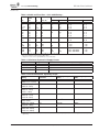
Powered by
Eaton Technology
VSD Series Drives
User Manual
November 2009
Supersedes September 2006
LIT-1201828
For more information visit: www.johnsoncontrols.com
Powered by
VSD Series Drives User Manual
Eaton Technology
November 2009
IMPORTANT NOTICE – PLEASE READ
The product discussed in this literature is subject to terms and conditions outlined in
Johnson Controls Inc. selling policies. The sole source governing the rights and remedies of
any purchaser of this equipment is the relevant Johnson Controls Inc. selling policy.
NO WARRANTIES, EXPRESS OR IMPLIED, INCLUDING WARRANTIES OF FITNESS FOR A
PARTICULAR PURPOSE OR MERCHANTABILITY, OR WARRANTIES ARISING FROM COURSE
OF DEALING OR USAGE OF TRADE, ARE MADE REGARDING THE INFORMATION,
RECOMMENDATIONS AND DESCRIPTIONS CONTAINED HEREIN. In no event will Johnson
Controls Inc. or Eaton Electrical Inc. be responsible to the purchaser or user in contract, in tort
(including negligence), strict liability or otherwise for any special, indirect, incidental or
consequential damage or loss whatsoever, including but not limited to damage or loss of use of
equipment, plant or power system, cost of capital, loss of power, additional expenses in the use
of existing power facilities, or claims against the purchaser or user by its customers resulting
from the use of the information, recommendations and descriptions contained herein.
The information contained in this manual is subject to change without notice.
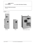
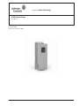
Cover Photo: Johnson Controls VSD Series Drive.
LIT-1201828
For more information visit: www.johnsoncontrols.com
i
VSD Series Drives User Manual
Powered by
Eaton Technology
November 2009
ii
For more information visit: www.johnsoncontrols.com
LIT-1201828
Powered by
VSD Series Drives User Manual
Eaton Technology
November 2009
Table of Contents
LIST OF FIGURES . . . . . . . . . . . . . . . . . . . . . . . . . . . . . . . . . . . . . . . . . . . . . . . . . . . . . . . . .
LIST OF TABLES . . . . . . . . . . . . . . . . . . . . . . . . . . . . . . . . . . . . . . . . . . . . . . . . . . . . . . . . . .
SAFETY ISSUES
Definitions and Symbols. . . . . . . . . . . . . . . . . . . . . . . . . . . . . . . . . . . . . . . . . . . . . . . .
Hazardous High Voltage . . . . . . . . . . . . . . . . . . . . . . . . . . . . . . . . . . . . . . . . . . . . . . . .
Warnings, Cautions and Notices . . . . . . . . . . . . . . . . . . . . . . . . . . . . . . . . . . . . . . . . .
LIT-1201828
v
vii
x
x
xi
CHAPTER 1 — OVERVIEW
How to Use This Manual. . . . . . . . . . . . . . . . . . . . . . . . . . . . . . . . . . . . . . . . . . . . . . . .
Receiving and Inspection . . . . . . . . . . . . . . . . . . . . . . . . . . . . . . . . . . . . . . . . . . . . . . .
Catalog Numbering System . . . . . . . . . . . . . . . . . . . . . . . . . . . . . . . . . . . . . . . . . . . . .
1-1
1-1
1-2
CHAPTER 2 — MOUNTING OPEN TYPE 1, TYPE 12 DRIVES
Space Requirements . . . . . . . . . . . . . . . . . . . . . . . . . . . . . . . . . . . . . . . . . . . . . . . . . . .
Environmental Requirements. . . . . . . . . . . . . . . . . . . . . . . . . . . . . . . . . . . . . . . . . . . .
Standard Mounting Instructions . . . . . . . . . . . . . . . . . . . . . . . . . . . . . . . . . . . . . . . . .
2-1
2-2
2-2
CHAPTER 3 — POWER WIRING
Guidelines . . . . . . . . . . . . . . . . . . . . . . . . . . . . . . . . . . . . . . . . . . . . . . . . . . . . . . . . . . .
UL Compatible Cable Selection and Installation . . . . . . . . . . . . . . . . . . . . . . . . . . . .
Installation Instructions. . . . . . . . . . . . . . . . . . . . . . . . . . . . . . . . . . . . . . . . . . . . . . . . .
Standard Wiring Diagrams and Terminal Locations . . . . . . . . . . . . . . . . . . . . . . . . .
Checking the Cable and Motor Insulation . . . . . . . . . . . . . . . . . . . . . . . . . . . . . . . . . .
3-1
3-2
3-4
3-6
3-9
CHAPTER 4 — CONTROL WIRING
General Information . . . . . . . . . . . . . . . . . . . . . . . . . . . . . . . . . . . . . . . . . . . . . . . . . . .
4-1
CHAPTER 5 — INTELLIPASS BYPASS OPTION
Product Description. . . . . . . . . . . . . . . . . . . . . . . . . . . . . . . . . . . . . . . . . . . . . . . . . . . .
Catalog Number Selection . . . . . . . . . . . . . . . . . . . . . . . . . . . . . . . . . . . . . . . . . . . . . .
IntelliPass Control Wiring Instructions . . . . . . . . . . . . . . . . . . . . . . . . . . . . . . . . . . . .
5-1
5-2
5-16
CHAPTER 6 — MENU INFORMATION
Keypad Operation . . . . . . . . . . . . . . . . . . . . . . . . . . . . . . . . . . . . . . . . . . . . . . . . . . . . .
Main Menu Navigation . . . . . . . . . . . . . . . . . . . . . . . . . . . . . . . . . . . . . . . . . . . . . . . . .
6-1
6-4
CHAPTER 7 — START-UP
Safety Precautions. . . . . . . . . . . . . . . . . . . . . . . . . . . . . . . . . . . . . . . . . . . . . . . . . . . . .
Sequence of Operation . . . . . . . . . . . . . . . . . . . . . . . . . . . . . . . . . . . . . . . . . . . . . . . . .
7-1
7-2
CHAPTER 8 — N2, XT, AND SA BUS COMMUNICATION
CHAPTER 9 — REMOTE INPUT APPLICATION (SVCHS200)
Introduction . . . . . . . . . . . . . . . . . . . . . . . . . . . . . . . . . . . . . . . . . . . . . . . . . . . . . . . . . .
Control Input/Output . . . . . . . . . . . . . . . . . . . . . . . . . . . . . . . . . . . . . . . . . . . . . . . . . . .
Parameter Lists . . . . . . . . . . . . . . . . . . . . . . . . . . . . . . . . . . . . . . . . . . . . . . . . . . . . . . .
9-1
9-2
9-3
CHAPTER 10 — GENERIC PI APPLICATION (SVCHS201)
Introduction . . . . . . . . . . . . . . . . . . . . . . . . . . . . . . . . . . . . . . . . . . . . . . . . . . . . . . . . . .
Control Input/Output . . . . . . . . . . . . . . . . . . . . . . . . . . . . . . . . . . . . . . . . . . . . . . . . . . .
Parameter Lists . . . . . . . . . . . . . . . . . . . . . . . . . . . . . . . . . . . . . . . . . . . . . . . . . . . . . . .
10-1
10-2
10-3
CHAPTER 11 — DUCT STATIC APPLICATION (SVCHS202)
Introduction . . . . . . . . . . . . . . . . . . . . . . . . . . . . . . . . . . . . . . . . . . . . . . . . . . . . . . . . . .
Control Input/Output . . . . . . . . . . . . . . . . . . . . . . . . . . . . . . . . . . . . . . . . . . . . . . . . . . .
Parameter Lists . . . . . . . . . . . . . . . . . . . . . . . . . . . . . . . . . . . . . . . . . . . . . . . . . . . . . . .
11-1
11-2
11-3
For more information visit: www.johnsoncontrols.com
iii
VSD Series Drives User Manual
Powered by
Eaton Technology
November 2009
Table of Contents, continued
CHAPTER 12 — BUILDING STATIC APPLICATION (SVCHS203)
Introduction . . . . . . . . . . . . . . . . . . . . . . . . . . . . . . . . . . . . . . . . . . . . . . . . . . . . . . . . . .
Control Input/Output . . . . . . . . . . . . . . . . . . . . . . . . . . . . . . . . . . . . . . . . . . . . . . . . . . .
Parameter Lists. . . . . . . . . . . . . . . . . . . . . . . . . . . . . . . . . . . . . . . . . . . . . . . . . . . . . . . .
12-1
12-2
12-3
CHAPTER 13 — PRESSURE CONTROL APPLICATION (SVCHS204)
Introduction . . . . . . . . . . . . . . . . . . . . . . . . . . . . . . . . . . . . . . . . . . . . . . . . . . . . . . . . . .
Control Input/Output . . . . . . . . . . . . . . . . . . . . . . . . . . . . . . . . . . . . . . . . . . . . . . . . . . .
Parameter Lists. . . . . . . . . . . . . . . . . . . . . . . . . . . . . . . . . . . . . . . . . . . . . . . . . . . . . . . .
13-1
13-2
13-3
CHAPTER 14 — TEMPERATURE CONTROL APPLICATION (SVCHS205)
Introduction . . . . . . . . . . . . . . . . . . . . . . . . . . . . . . . . . . . . . . . . . . . . . . . . . . . . . . . . . .
Control Input/Output . . . . . . . . . . . . . . . . . . . . . . . . . . . . . . . . . . . . . . . . . . . . . . . . . . .
Parameter Lists. . . . . . . . . . . . . . . . . . . . . . . . . . . . . . . . . . . . . . . . . . . . . . . . . . . . . . . .
14-1
14-2
14-3
CHAPTER 15 — DESCRIPTION OF PARAMETERS
Parameters by ID Number . . . . . . . . . . . . . . . . . . . . . . . . . . . . . . . . . . . . . . . . . . . . . . . 15-1
Keypad Control Parameters . . . . . . . . . . . . . . . . . . . . . . . . . . . . . . . . . . . . . . . . . . . . . 15-28
APPENDIX A — TECHNICAL DATA
Specifications . . . . . . . . . . . . . . . . . . . . . . . . . . . . . . . . . . . . . . . . . . . . . . . . . . . . . . . . .
Power Ratings. . . . . . . . . . . . . . . . . . . . . . . . . . . . . . . . . . . . . . . . . . . . . . . . . . . . . . . . .
Power Loss and Switching Frequency . . . . . . . . . . . . . . . . . . . . . . . . . . . . . . . . . . . . .
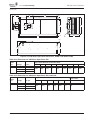
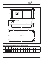
Dimensions . . . . . . . . . . . . . . . . . . . . . . . . . . . . . . . . . . . . . . . . . . . . . . . . . . . . . . . . . . .
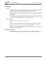
EMC Capability . . . . . . . . . . . . . . . . . . . . . . . . . . . . . . . . . . . . . . . . . . . . . . . . . . . . . . . . .
Declaration of Conformity . . . . . . . . . . . . . . . . . . . . . . . . . . . . . . . . . . . . . . . . . . . . . . . .
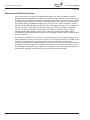
Warranty and Liability Information. . . . . . . . . . . . . . . . . . . . . . . . . . . . . . . . . . . . . . . . .
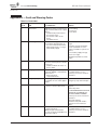
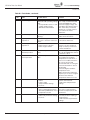
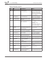
APPENDIX B — FAULT AND WARNING CODES
APPENDIX C — ACCESSORIES
RS-232 Cables Used with VS Drives . . . . . . . . . . . . . . . . . . . . . . . . . . . . . . . . . . . . . . .
A-1
A-3
A-4
A-8
A-15
A-15
A-16
C-1
APPENDIX D — WIRING DIAGRAMS
iv
For more information visit: www.johnsoncontrols.com
LIT-1201828
Powered by
VSD Series Drives User Manual
Eaton Technology
November 2009
List of Figures
Figure 2-1: Mounting Space Requirements . . . . . . . . . . . . . . . . . . . . . . . . . . . . . . . . . . . .
Figure 3-1: Input Power and Motor Cable Stripping and Wire Lengths . . . . . . . . . . . . . .
Figure 3-2: . . . . . . . . . . . . . . . . . . . . . . . . . . . . . . . . . . . . . . . . . . . . . . . . . . . . . . . . . . . . . . .
Figure 3-3: Principle Wiring Diagram of VSD Series Power Unit,
FR4, FR5 and FR6 . . . . . . . . . . . . . . . . . . . . . . . . . . . . . . . . . . . . . . . . . . . . . . . . . . . . .
Figure 3-4: . . . . . . . . . . . . . . . . . . . . . . . . . . . . . . . . . . . . . . . . . . . . . . . . . . . . . . . . . . . . . . .
Figure 3-5: Option Board A9 Location and Settings . . . . . . . . . . . . . . . . . . . . . . . . . . . . . .
Figure 4-1: Option Board Slots . . . . . . . . . . . . . . . . . . . . . . . . . . . . . . . . . . . . . . . . . . . . . . .
Figure 4-2: Option Board A2 Terminal Locations . . . . . . . . . . . . . . . . . . . . . . . . . . . . . . . .
Figure 4-3: Positive/Negative Logic . . . . . . . . . . . . . . . . . . . . . . . . . . . . . . . . . . . . . . . . . . .
Figure 5-1: Identification of NEMA Type 1 Components . . . . . . . . . . . . . . . . . . . . . . . . . .
Figure 5-2: VSD Series IntelliPass/IntelliDisconnect Drive Dimensions . . . . . . . . . . . . . .
Figure 5-3: VSD Series IntelliPass with Three Contactors . . . . . . . . . . . . . . . . . . . . . . . . .
Figure 5-4: Identification of NEMA Type 12 and NEMA Type 3R Components . . . . . . . .
Figure 5-5: VSD Series Enclosed Drive Dimensions . . . . . . . . . . . . . . . . . . . . . . . . . . . . .
Figure 5-6: . . . . . . . . . . . . . . . . . . . . . . . . . . . . . . . . . . . . . . . . . . . . . . . . . . . . . . . . . . . . . . .
Figure 5-7: Schematic for Static Checks (Sample for Frames 4 and 5) . . . . . . . . . . . . . . .
Figure 5-8: Option Board B5 Wiring Diagram . . . . . . . . . . . . . . . . . . . . . . . . . . . . . . . . . . .
Figure 5-9: Option Board B5 Terminal Location . . . . . . . . . . . . . . . . . . . . . . . . . . . . . . . . .
Figure 5-10: Enable Bypass . . . . . . . . . . . . . . . . . . . . . . . . . . . . . . . . . . . . . . . . . . . . . . . . .
Figure 6-1: Keypad and Display . . . . . . . . . . . . . . . . . . . . . . . . . . . . . . . . . . . . . . . . . . . . . .
Figure 6-2: Operate Menu Navigation . . . . . . . . . . . . . . . . . . . . . . . . . . . . . . . . . . . . . . . . .
Figure 6-3: Main Menu Navigation . . . . . . . . . . . . . . . . . . . . . . . . . . . . . . . . . . . . . . . . . . .
Figure 6-4: Parameter Menu Structure Example . . . . . . . . . . . . . . . . . . . . . . . . . . . . . . . .
Figure 6-5: Keypad Control Menu . . . . . . . . . . . . . . . . . . . . . . . . . . . . . . . . . . . . . . . . . . . .
Figure 6-6: Active Fault Display Example . . . . . . . . . . . . . . . . . . . . . . . . . . . . . . . . . . . . . .
Figure 6-7: Sample Fault History Display . . . . . . . . . . . . . . . . . . . . . . . . . . . . . . . . . . . . . .
Figure 6-8: System Menu Keypad Structure . . . . . . . . . . . . . . . . . . . . . . . . . . . . . . . . . . . .
Figure 6-9: Expander Board Menu Structure . . . . . . . . . . . . . . . . . . . . . . . . . . . . . . . . . . .
Figure 6-10: Digital Inputs — DI-1, DI-2, DI-3 Status . . . . . . . . . . . . . . . . . . . . . . . . . . . . . .
Figure 6-11: Digital Inputs — DI-4, DI-5, DI-6 Status . . . . . . . . . . . . . . . . . . . . . . . . . . . . . .
Figure 6-12: Digital and Relay Outputs — DO-1, RO-1, RO-2 Status . . . . . . . . . . . . . . . . .
Figure 7-1: Start-Up Wizard Navigation (1 of 3) . . . . . . . . . . . . . . . . . . . . . . . . . . . . . . . . .
Figure 7-2: Start-Up Wizard Navigation (2 of 3) . . . . . . . . . . . . . . . . . . . . . . . . . . . . . . . . .
Figure 7-3: Start-Up Wizard Navigation (3 of 3) . . . . . . . . . . . . . . . . . . . . . . . . . . . . . . . . .
Figure 7-4: Remote Input Start-Up Wizard . . . . . . . . . . . . . . . . . . . . . . . . . . . . . . . . . . . . .
Figure 15-1: AI-1 No Signal Inversion . . . . . . . . . . . . . . . . . . . . . . . . . . . . . . . . . . . . . . . . .
Figure 15-2: AI-1 Signal Inversion . . . . . . . . . . . . . . . . . . . . . . . . . . . . . . . . . . . . . . . . . . . .
Figure 15-3: AI-1 No Signal Filtering . . . . . . . . . . . . . . . . . . . . . . . . . . . . . . . . . . . . . . . . . .
Figure 15-4: Analog Input AI-2 Scaling . . . . . . . . . . . . . . . . . . . . . . . . . . . . . . . . . . . . . . . .
Figure 15-5: Setpoint Scaling . . . . . . . . . . . . . . . . . . . . . . . . . . . . . . . . . . . . . . . . . . . . . . . .
Figure 15-6: Sensor Scaling . . . . . . . . . . . . . . . . . . . . . . . . . . . . . . . . . . . . . . . . . . . . . . . . .
Figure 15-7: Analog Output Filtering . . . . . . . . . . . . . . . . . . . . . . . . . . . . . . . . . . . . . . . . . .
Figure 15-8: Analog Output Invert . . . . . . . . . . . . . . . . . . . . . . . . . . . . . . . . . . . . . . . . . . . .
Figure 15-9: Analog Output Scaling . . . . . . . . . . . . . . . . . . . . . . . . . . . . . . . . . . . . . . . . . .
Figure 15-10: Output Frequency Supervision . . . . . . . . . . . . . . . . . . . . . . . . . . . . . . . . . . .
Figure 15-11: Acceleration/Deceleration (S-shaped) . . . . . . . . . . . . . . . . . . . . . . . . . . . . .
Figure 15-12: Example of Prohibit Frequency Area Setting . . . . . . . . . . . . . . . . . . . . . . .
Figure 15-13: Ramp Speed Scaling between Prohibit Frequencies . . . . . . . . . . . . . . . . .
Figure 15-14: Linear and Squared V/Hz Ratio . . . . . . . . . . . . . . . . . . . . . . . . . . . . . . . . . . .
Figure 15-15: Programmable V/Hz Curve . . . . . . . . . . . . . . . . . . . . . . . . . . . . . . . . . . . . . .
Figure 15-16: Motor Thermal Current IT Curve . . . . . . . . . . . . . . . . . . . . . . . . . . . . . . . . .
LIT-1201828
For more information visit: www.johnsoncontrols.com
2-1
3-4
3-5
3-6
3-8
3-8
4-1
4-2
4-2
5-4
5-4
5-7
5-9
5-9
5-12
5-15
5-16
5-17
5-17
6-1
6-1
6-5
6-6
6-7
6-8
6-10
6-11
6-19
6-20
6-21
6-21
7-4
7-5
7-6
7-7
15-4
15-4
15-5
15-5
15-6
15-6
15-7
15-8
15-9
15-11
15-13
15-14
15-15
15-17
15-17
15-21
v
VSD Series Drives User Manual
Powered by
Eaton Technology
November 2009
List of Figures, continued
Figure 15-17: Motor Temperature Calculation . . . . . . . . . . . . . . . . . . . . . . . . . . . . . . . . . .
Figure 15-18: Stall Characteristics Settings . . . . . . . . . . . . . . . . . . . . . . . . . . . . . . . . . . . . .
Figure 15-19: Stall Time Count . . . . . . . . . . . . . . . . . . . . . . . . . . . . . . . . . . . . . . . . . . . . . . .
Figure 15-20: Setting of Minimum Load . . . . . . . . . . . . . . . . . . . . . . . . . . . . . . . . . . . . . . .
Figure 15-21: Underload Time Counter Function . . . . . . . . . . . . . . . . . . . . . . . . . . . . . . . .
Figure 15-22: Auto Acceleration/Deceleration (S-shaped) . . . . . . . . . . . . . . . . . . . . . . . . .
Figure A-1: Power Loss as Function of Switching Frequency:
1 – 3 hp 230V, 1-1/2 – 7-1/2 hp 480V . . . . . . . . . . . . . . . . . . . . . . . . . . . . . . . . . . . . . . .
Figure A-2: Power Loss as Function of Switching Frequency:
5 – 10 hp 230V, 10 – 20 hp 480V . . . . . . . . . . . . . . . . . . . . . . . . . . . . . . . . . . . . . . . . . .
Figure A-3: Power Loss as Function of Switching Frequency:
15 – 20 hp 230V, 25 – 40 hp 480V . . . . . . . . . . . . . . . . . . . . . . . . . . . . . . . . . . . . . . . . .
Figure A-4: Power Loss as Function of Switching Frequency:
25 – 40 hp 230V, 50 – 75 hp 480V . . . . . . . . . . . . . . . . . . . . . . . . . . . . . . . . . . . . . . . . .
Figure A-5: Power Loss as Function of Switching Frequency:
50 – 75 hp 230V, 100 – 150 hp 480V . . . . . . . . . . . . . . . . . . . . . . . . . . . . . . . . . . . . . . .
Figure A-6: Power Loss as Function of Switching Frequency:
200 – 250 hp 480V . . . . . . . . . . . . . . . . . . . . . . . . . . . . . . . . . . . . . . . . . . . . . . . . . . . . .
Figure A-7: TYPE 1 and TYPE 12 VSD Series Open Drive Dimensions,
FR4, FR5 and FR6 . . . . . . . . . . . . . . . . . . . . . . . . . . . . . . . . . . . . . . . . . . . . . . . . . . . . . .
Figure A-8: VSD Series Open Drive Dimensions, TYPE 1 and TYPE 12
with Flange Kit, FR4, FR5 and FR6 . . . . . . . . . . . . . . . . . . . . . . . . . . . . . . . . . . . . . . . .
Figure A-9: VSD Series Open Drive Dimensions, TYPE 1 and TYPE 12, FR7 . . . . . . . . . .
Figure A-10: VSD Series Open Drive Dimensions, TYPE 1 and TYPE 12, FR8 . . . . . . . . .
Figure A-11: VSD Series Open Drive Dimensions, TYPE 1 and TYPE 12,
with Flange Kit, FR7 and FR8 . . . . . . . . . . . . . . . . . . . . . . . . . . . . . . . . . . . . . . . . . . . .
Figure A-12: VSD Series Open Drive Dimensions, OPEN 1 and OPEN 12 FR9 . . . . . . . . .
Figure A-13: VSD Series Open Drive Dimensions, TYPE 1 and TYPE 12 FR9
with Flange Kit . . . . . . . . . . . . . . . . . . . . . . . . . . . . . . . . . . . . . . . . . . . . . . . . . . . . . . . .
Figure C-1: RS-232 Cable for Parameter Setting or
Software Downloading by Using PC . . . . . . . . . . . . . . . . . . . . . . . . . . . . . . . . . . . . . .
Figure C-2: Connection of Cable Used with Keypad . . . . . . . . . . . . . . . . . . . . . . . . . . . . . .
Figure C-3: RS-232 Cable . . . . . . . . . . . . . . . . . . . . . . . . . . . . . . . . . . . . . . . . . . . . . . . . . . . .
Figure D-1: VSD Series IntelliPass with Three Contactors . . . . . . . . . . . . . . . . . . . . . . . . .
Figure D-2: VSD Series IntelliPass Disconnect . . . . . . . . . . . . . . . . . . . . . . . . . . . . . . . . . .
vi
For more information visit: www.johnsoncontrols.com
15-22
15-23
15-23
15-24
15-25
15-27
A-5
A-5
A-6
A-6
A-7
A-7
A-8
A-9
A-10
A-11
A-12
A-13
A-14
C-1
C-1
C-2
D-1
D-2
LIT-1201828
Powered by
VSD Series Drives User Manual
Eaton Technology
November 2009
List of Tables
Table 1-1: VSD Series Open Drives Selection Chart . . . . . . . . . . . . . . . . . . . . . . . . . . . . .
Table 2-1: Space Requirements for Mounting a VSD Series Drive . . . . . . . . . . . . . . . . . .
Table 2-2: Cooling Airflow Requirements . . . . . . . . . . . . . . . . . . . . . . . . . . . . . . . . . . . . . .
Table 3-1: Cable Spacings . . . . . . . . . . . . . . . . . . . . . . . . . . . . . . . . . . . . . . . . . . . . . . . . . .
Table 3-2: Cable and Fuse Sizes — 208 – 240V Ratings . . . . . . . . . . . . . . . . . . . . . . . . .
Table 3-3: Cable and Fuse Sizes — 380 – 500V Ratings . . . . . . . . . . . . . . . . . . . . . . . . .
Table 3-4: Cable and Fuse Sizes — 525 – 690V Ratings . . . . . . . . . . . . . . . . . . . . . . . . .
Table 3-5: Maximum Symmetrical Supply Current . . . . . . . . . . . . . . . . . . . . . . . . . . . . . .
Table 3-6: Power Connection Tightening Torque . . . . . . . . . . . . . . . . . . . . . . . . . . . . . . . .
Table 3-7: Power and Motor Cable Stripping Lengths . . . . . . . . . . . . . . . . . . . . . . . . . . . .
Table 3-8: Control Wiring Instructions — NEMA Type 1/12 Open Drives . . . . . . . . . . .
Table 4-1: Option Board A2 Terminal Descriptions . . . . . . . . . . . . . . . . . . . . . . . . . . . . . .
Table 5-1: VSD Series IntelliPass/IntelliDisconnect Drives Selection Chart . . . . . . . . . . .
Table 5-2: VSD Series Enclosed Drives Selection Chart . . . . . . . . . . . . . . . . . . . . . . . . . .
Table 5-3: Options List . . . . . . . . . . . . . . . . . . . . . . . . . . . . . . . . . . . . . . . . . . . . . . . . . . . . .
Table 5-4: Option Notes . . . . . . . . . . . . . . . . . . . . . . . . . . . . . . . . . . . . . . . . . . . . . . . . . . . .
Table 5-5: VSD Series NEMA Type 1 IntelliPass/IntelliDisconnect Drive
Dimensions . . . . . . . . . . . . . . . . . . . . . . . . . . . . . . . . . . . . . . . . . . . . . . . . . . . . . . . . . .
Table 5-6: Bypass Power Wiring Instructions —
NEMA Type 1 IntelliPass/IntelliDisconnect Drive . . . . . . . . . . . . . . . . . . . . . . . . . . . .
Table 5-7: VSD Series NEMA Type 12 Enclosed IntelliPass Drive Dimensions . . . . . . . .
Table 5-8: VSD Series NEMA Type 3R Enclosed IntelliPass Drive Dimensions . . . . . . . .
Table 5-9: Bypass Power Wiring Instructions — Enclosed NEMA Type 12/3R . . . . . . . .
Table 5-10: Static Checks of Converter . . . . . . . . . . . . . . . . . . . . . . . . . . . . . . . . . . . . . . . .
Table 5-11: Static Checks of Inverter . . . . . . . . . . . . . . . . . . . . . . . . . . . . . . . . . . . . . . . . . .
Table 5-12: Static Checks of DC Bus . . . . . . . . . . . . . . . . . . . . . . . . . . . . . . . . . . . . . . . . . .
Table 5-13: Option Board B5 Terminal Descriptions . . . . . . . . . . . . . . . . . . . . . . . . . . . . .
Table 6-1: LCD Status Indicators . . . . . . . . . . . . . . . . . . . . . . . . . . . . . . . . . . . . . . . . . . . . .
Table 6-2: LED Status Indicators . . . . . . . . . . . . . . . . . . . . . . . . . . . . . . . . . . . . . . . . . . . . .
Table 6-3: Navigation Buttons . . . . . . . . . . . . . . . . . . . . . . . . . . . . . . . . . . . . . . . . . . . . . . .
Table 6-4: Fault Types . . . . . . . . . . . . . . . . . . . . . . . . . . . . . . . . . . . . . . . . . . . . . . . . . . . . . .
Table 6-5: Fault Time Data . . . . . . . . . . . . . . . . . . . . . . . . . . . . . . . . . . . . . . . . . . . . . . . . . .
Table 6-6: Total Counters . . . . . . . . . . . . . . . . . . . . . . . . . . . . . . . . . . . . . . . . . . . . . . . . . . .
Table 6-7: Trip Counters . . . . . . . . . . . . . . . . . . . . . . . . . . . . . . . . . . . . . . . . . . . . . . . . . . .
Table 6-8: Software Information . . . . . . . . . . . . . . . . . . . . . . . . . . . . . . . . . . . . . . . . . . . . .
Table 6-9: Application Information . . . . . . . . . . . . . . . . . . . . . . . . . . . . . . . . . . . . . . . . . . .
Table 6-10: Hardware Information . . . . . . . . . . . . . . . . . . . . . . . . . . . . . . . . . . . . . . . . . . . .
Table 6-11: Expander Board Information . . . . . . . . . . . . . . . . . . . . . . . . . . . . . . . . . . . . . .
Table 6-12: Drive Output Phase Current Measurement . . . . . . . . . . . . . . . . . . . . . . . . . . .
Table 6-13: Monitoring Menu Items — Generic PI Application Example . . . . . . . . . . . . .
Table 6-14: Operate Menu Items — Generic PI Application Example . . . . . . . . . . . . . . .
Table 9-1: Remote Input Application Default I/O Configuration . . . . . . . . . . . . . . . . . . . .
Table 9-2: Quick Setup Parameters — M1 ➔ G1.1 . . . . . . . . . . . . . . . . . . . . . . . . . . . . . .
Table 9-3: Input Signals — M1 ➔ G1.2 . . . . . . . . . . . . . . . . . . . . . . . . . . . . . . . . . . . . . . . .
Table 9-4: Output Signals — M1 ➔ G1.3 . . . . . . . . . . . . . . . . . . . . . . . . . . . . . . . . . . . . . . .
Table 9-5: Drive Control Parameters — M1 ➔ G1.4 . . . . . . . . . . . . . . . . . . . . . . . . . . . . . .
Table 9-6: Prohibit Frequencies — M1 ➔ G1.5 . . . . . . . . . . . . . . . . . . . . . . . . . . . . . . . . . .
Table 9-7: Motor Control Parameters — M1 ➔ G1.6 . . . . . . . . . . . . . . . . . . . . . . . . . . . . .
Table 9-8: Protections — M1 ➔ G1.7 . . . . . . . . . . . . . . . . . . . . . . . . . . . . . . . . . . . . . . . . . .
LIT-1201828
For more information visit: www.johnsoncontrols.com
1-2
2-1
2-2
3-1
3-2
3-2
3-3
3-3
3-3
3-4
3-5
4-2
5-2
5-3
5-3
5-3
5-4
5-5
5-9
5-9
5-10
5-14
5-14
5-15
5-16
6-2
6-2
6-3
6-9
6-9
6-16
6-17
6-17
6-17
6-18
6-18
6-18
6-20
6-21
9-2
9-3
9-5
9-8
9-10
9-11
9-12
9-13
vii
VSD Series Drives User Manual
Powered by
Eaton Technology
November 2009
List of Tables, continued
Table 9-9: Fieldbus Parameters — M1 ➔ G1.8 . . . . . . . . . . . . . . . . . . . . . . . . . . . . . . . . . .
Table 9-10: Preset Speeds — M1 ➔ G1.10 . . . . . . . . . . . . . . . . . . . . . . . . . . . . . . . . . . . . . .
Table 9-11: Keypad Control Parameters — M2 . . . . . . . . . . . . . . . . . . . . . . . . . . . . . . . . . .
Table 9-12: Monitoring Menu . . . . . . . . . . . . . . . . . . . . . . . . . . . . . . . . . . . . . . . . . . . . . . . .
Table 10-1: Generic PI Application Default I/O Configuration . . . . . . . . . . . . . . . . . . . . . .
Table 10-2: Quick Setup Parameters — M1 ➔ G1.1 . . . . . . . . . . . . . . . . . . . . . . . . . . . . . .
Table 10-3: Input Signals — M1 ➔ G1.2 . . . . . . . . . . . . . . . . . . . . . . . . . . . . . . . . . . . . . . . .
Table 10-4: Output Signals — M1 ➔ G1.3 . . . . . . . . . . . . . . . . . . . . . . . . . . . . . . . . . . . . . .
Table 10-5: Drive Control Parameters — M1 ➔ G1.4 . . . . . . . . . . . . . . . . . . . . . . . . . . . . .
Table 10-6: Prohibit Frequencies — M1 ➔ G1.5 . . . . . . . . . . . . . . . . . . . . . . . . . . . . . . . . .
Table 10-7: Motor Control Parameters — M1 ➔ G1.6 . . . . . . . . . . . . . . . . . . . . . . . . . . . . .
Table 10-8: Protections — M1 ➔ G1.7 . . . . . . . . . . . . . . . . . . . . . . . . . . . . . . . . . . . . . . . . .
Table 10-9: Fieldbus Parameters — M1 ➔ G1.8 . . . . . . . . . . . . . . . . . . . . . . . . . . . . . . . . .
Table 10-10: PI-Control Parameters — M1 ➔ G1.9 . . . . . . . . . . . . . . . . . . . . . . . . . . . . . . .
Table 10-11: Preset Speeds — M1 ➔ G1.10 . . . . . . . . . . . . . . . . . . . . . . . . . . . . . . . . . . . . .
Table 10-12: Keypad Control Parameters — M2 . . . . . . . . . . . . . . . . . . . . . . . . . . . . . . . . .
Table 10-13: Monitoring Menu . . . . . . . . . . . . . . . . . . . . . . . . . . . . . . . . . . . . . . . . . . . . . . .
Table 11-1: Duct Static Application Default I/O Configuration . . . . . . . . . . . . . . . . . . . . .
Table 11-2: Quick Setup Parameters — M1 ➔ G1.1 . . . . . . . . . . . . . . . . . . . . . . . . . . . . . .
Table 11-3: Input Signals — M1 ➔ G1.2 . . . . . . . . . . . . . . . . . . . . . . . . . . . . . . . . . . . . . . . .
Table 11-4: Output Signals — M1 ➔ G1.3 . . . . . . . . . . . . . . . . . . . . . . . . . . . . . . . . . . . . . .
Table 11-5: Drive Control Parameters — M1 ➔ G1.4 . . . . . . . . . . . . . . . . . . . . . . . . . . . . .
Table 11-6: Prohibit Frequencies — M1 ➔ G1.5 . . . . . . . . . . . . . . . . . . . . . . . . . . . . . . . . .
Table 11-7: Motor Control Parameters — M1 ➔ G1.6 . . . . . . . . . . . . . . . . . . . . . . . . . . . . .
Table 11-8: Protections — M1 ➔ G1.7 . . . . . . . . . . . . . . . . . . . . . . . . . . . . . . . . . . . . . . . . .
Table 11-9: Fieldbus Parameters — M1 ➔ G1.8 . . . . . . . . . . . . . . . . . . . . . . . . . . . . . . . . .
Table 11-10: PI-Control Parameters — M1 ➔ G1.9 . . . . . . . . . . . . . . . . . . . . . . . . . . . . . . .
Table 11-11: Preset Speeds — M1 ➔ G1.10 . . . . . . . . . . . . . . . . . . . . . . . . . . . . . . . . . . . . .
Table 11-12: Keypad Control Parameters — M2 . . . . . . . . . . . . . . . . . . . . . . . . . . . . . . . . .
Table 11-13: Monitoring Menu . . . . . . . . . . . . . . . . . . . . . . . . . . . . . . . . . . . . . . . . . . . . . . .
Table 12-1: Building Static Application Default I/O Configuration . . . . . . . . . . . . . . . . . .
Table 12-2: Quick Setup Parameters — M1 ➔ G1.1 . . . . . . . . . . . . . . . . . . . . . . . . . . . . . .
Table 12-3: Input Signals — M1 ➔ G1.2 . . . . . . . . . . . . . . . . . . . . . . . . . . . . . . . . . . . . . . . .
Table 12-4: Output Signals — M1 ➔ G1.3 . . . . . . . . . . . . . . . . . . . . . . . . . . . . . . . . . . . . . .
Table 12-5: Drive Control Parameters — M1 ➔ G1.4 . . . . . . . . . . . . . . . . . . . . . . . . . . . . .
Table 12-6: Prohibit Frequencies — M1 ➔ G1.5 . . . . . . . . . . . . . . . . . . . . . . . . . . . . . . . . .
Table 12-7: Motor Control Parameters — M1 ➔ G1.6 . . . . . . . . . . . . . . . . . . . . . . . . . . . . .
Table 12-8: Protections — M1 ➔ G1.7 . . . . . . . . . . . . . . . . . . . . . . . . . . . . . . . . . . . . . . . . .
Table 12-9: Fieldbus Parameters — M1 ➔ G1.8 . . . . . . . . . . . . . . . . . . . . . . . . . . . . . . . . .
Table 12-10: PI-Control Parameters — M1 ➔ G1.9 . . . . . . . . . . . . . . . . . . . . . . . . . . . . . . .
Table 12-11: Preset Speeds — M1 ➔ G1.10 . . . . . . . . . . . . . . . . . . . . . . . . . . . . . . . . . . . . .
Table 12-12: Keypad Control Parameters — M2 . . . . . . . . . . . . . . . . . . . . . . . . . . . . . . . . .
Table 12-13: Monitoring Menu . . . . . . . . . . . . . . . . . . . . . . . . . . . . . . . . . . . . . . . . . . . . . . .
Table 13-1: Pressure Control Application Default I/O Configuration . . . . . . . . . . . . . . . .
Table 13-2: Quick Setup Parameters — M1 ➔ G1.1 . . . . . . . . . . . . . . . . . . . . . . . . . . . . . .
Table 13-3: Input Signals — M1 ➔ G1.2 . . . . . . . . . . . . . . . . . . . . . . . . . . . . . . . . . . . . . . . .
Table 13-4: Output Signals — M1 ➔ G1.3 . . . . . . . . . . . . . . . . . . . . . . . . . . . . . . . . . . . . . .
Table 13-5: Drive Control Parameters — M1 ➔ G1.4 . . . . . . . . . . . . . . . . . . . . . . . . . . . . .
Table 13-6: Prohibit Frequencies — M1 ➔ G1.5 . . . . . . . . . . . . . . . . . . . . . . . . . . . . . . . . .
Table 13-7: Motor Control Parameters — M1 ➔ G1.6 . . . . . . . . . . . . . . . . . . . . . . . . . . . . .
viii
For more information visit: www.johnsoncontrols.com
9-14
9-15
9-16
9-16
10-2
10-3
10-5
10-8
10-10
10-11
10-12
10-13
10-14
10-16
10-16
10-17
10-17
11-2
11-3
11-5
11-8
11-10
11-11
11-12
11-13
11-14
11-16
11-16
11-17
11-18
12-2
12-3
12-5
12-8
12-10
12-11
12-12
12-13
12-14
12-16
12-16
12-17
12-18
13-2
13-3
13-5
13-8
13-10
13-11
13-12
LIT-1201828
Powered by
VSD Series Drives User Manual
Eaton Technology
November 2009
List of Tables, continued
Table 13-8: Protections — M1 ➔ G1.7 . . . . . . . . . . . . . . . . . . . . . . . . . . . . . . . . . . . . . . . . .
Table 13-9: Fieldbus Parameters — M1 ➔ G1.8 . . . . . . . . . . . . . . . . . . . . . . . . . . . . . . . . .
Table 13-10: PI-Control Parameters — M1 ➔ G1.9 . . . . . . . . . . . . . . . . . . . . . . . . . . . . . . .
Table 13-11: Preset Speeds — M1 ➔ G1.10 . . . . . . . . . . . . . . . . . . . . . . . . . . . . . . . . . . . .
Table 13-12: Keypad Control Parameters — M2 . . . . . . . . . . . . . . . . . . . . . . . . . . . . . . . . .
Table 13-13: Monitoring Menu . . . . . . . . . . . . . . . . . . . . . . . . . . . . . . . . . . . . . . . . . . . . . . .
Table 14-1: Temperature Control Application Default I/O Configuration . . . . . . . . . . . .
Table 14-2: Quick Setup Parameters — M1 ➔ G1.1 . . . . . . . . . . . . . . . . . . . . . . . . . . . . .
Table 14-3: Input Signals — M1 ➔ G1.2 . . . . . . . . . . . . . . . . . . . . . . . . . . . . . . . . . . . . . . .
Table 14-4: Output Signals — M1 ➔ G1.3 . . . . . . . . . . . . . . . . . . . . . . . . . . . . . . . . . . . . . .
Table 14-5: Drive Control Parameters — M1 ➔ G1.4 . . . . . . . . . . . . . . . . . . . . . . . . . . . . .
Table 14-6: Prohibit Frequencies — M1 ➔ G1.5 . . . . . . . . . . . . . . . . . . . . . . . . . . . . . . . . .
Table 14-7: Motor Control Parameters — M1 ➔ G1.6 . . . . . . . . . . . . . . . . . . . . . . . . . . . .
Table 14-8: Protections — M1 ➔ G1.7 . . . . . . . . . . . . . . . . . . . . . . . . . . . . . . . . . . . . . . . . .
Table 14-9: Fieldbus Parameters — M1 ➔ G1.8 . . . . . . . . . . . . . . . . . . . . . . . . . . . . . . . . .
Table 14-10: PI-Control Parameters — M1 ➔ G1.9 . . . . . . . . . . . . . . . . . . . . . . . . . . . . . . .
Table 14-11: Preset Speeds — M1 ➔ G1.10 . . . . . . . . . . . . . . . . . . . . . . . . . . . . . . . . . . . .
Table 14-12: Keypad Control Parameters — M2 . . . . . . . . . . . . . . . . . . . . . . . . . . . . . . . . .
Table 14-13: Monitoring Menu . . . . . . . . . . . . . . . . . . . . . . . . . . . . . . . . . . . . . . . . . . . . . . .
Table 15-1: Selections for IDs 112, 113, 114 and 115 . . . . . . . . . . . . . . . . . . . . . . . . . . . . .
Table 15-2: Analog Output Scaling . . . . . . . . . . . . . . . . . . . . . . . . . . . . . . . . . . . . . . . . . . .
Table 15-3: Output Signals Via DO-1 and Output Relays RO-1 and RO-2 . . . . . . . . . . . .
Table 15-4: Size-Dependent Switching Frequencies . . . . . . . . . . . . . . . . . . . . . . . . . . . . .
Table 15-5: Fieldbus Parameters . . . . . . . . . . . . . . . . . . . . . . . . . . . . . . . . . . . . . . . . . . . . .
Table 15-6: Preset Speeds . . . . . . . . . . . . . . . . . . . . . . . . . . . . . . . . . . . . . . . . . . . . . . . . . .
Table A-1: VSD Series Drive Specifications . . . . . . . . . . . . . . . . . . . . . . . . . . . . . . . . . . . .
Table A-2: 230V VT Output Power Ratings . . . . . . . . . . . . . . . . . . . . . . . . . . . . . . . . . . . . .
Table A-3: 480V VT Output Power Ratings . . . . . . . . . . . . . . . . . . . . . . . . . . . . . . . . . . . . .
Table A-4: 575V VT Output Power Ratings . . . . . . . . . . . . . . . . . . . . . . . . . . . . . . . . . . . . .
Table A-5: VSD Series Open Drive Dimensions . . . . . . . . . . . . . . . . . . . . . . . . . . . . . . . .
Table A-6: Dimensions for VSD Series Open Drive, FR4, FR5 and FR6
with Flange Kit . . . . . . . . . . . . . . . . . . . . . . . . . . . . . . . . . . . . . . . . . . . . . . . . . . . . . . .
Table A-7: Dimensions for the Flange Opening, FR4 to FR6 . . . . . . . . . . . . . . . . . . . . . . .
Table A-8: VSD Series Open Drive Dimensions, FR7 . . . . . . . . . . . . . . . . . . . . . . . . . . . . .
Table A-9: VSD Series Open Drive Dimensions, FR8 . . . . . . . . . . . . . . . . . . . . . . . . . . . . .
Table A-10: Dimensions for VSD Series Open Drive, FR7 and FR8
with Flange Kit . . . . . . . . . . . . . . . . . . . . . . . . . . . . . . . . . . . . . . . . . . . . . . . . . . . . . . .
Table A-11: Dimensions for the Flange Opening, FR7/FR8 . . . . . . . . . . . . . . . . . . . . . . . .
Table A-12: Dimensions for VSD Series Open Drive, FR9 . . . . . . . . . . . . . . . . . . . . . . . . .
Table A-12: Dimensions for VSD Series Open Drive, FR9, continued . . . . . . . . . . . . . . .
Table A-13: Dimensions for VSD Series Open Drive, FR9 with Flange Kit . . . . . . . . . . . .
Table B-1: Fault Codes . . . . . . . . . . . . . . . . . . . . . . . . . . . . . . . . . . . . . . . . . . . . . . . . . . . . .
LIT-1201828
For more information visit: www.johnsoncontrols.com
13-13
13-14
13-16
13-16
13-17
13-18
14-2
14-3
14-5
14-8
14-10
14-11
14-12
14-13
14-14
14-16
14-16
14-17
14-18
15-2
15-8
15-9
15-18
15-26
15-28
A-1
A-3
A-3
A-4
A-8
A-9
A-9
A-10
A-11
A-12
A-12
A-13
A-13
A-14
B-1
ix
VSD Series Drives User Manual
Powered by
Eaton Technology
November 2009
Safety Issues
Definitions and Symbols
WARNING
This symbol indicates high voltage. It calls your attention to items
or operations that could be dangerous to you and other persons
operating this equipment. Read the message and follow the
instructions carefully.
This symbol is the “Safety Alert Symbol.” It occurs with either of
two signal words: WARNING or CAUTION as described below.
WARNING
Indicates a potentially hazardous situation which, if not avoided,
can result in serious injury or death.
CAUTION
Indicates a potentially hazardous situation which, if not avoided,
can result in minor to moderate injury, or serious damage to the
equipment. The situation described in the CAUTION may, if not
avoided, lead to serious results. Important safety measures are
described in CAUTION (as well as WARNING).
Hazardous High Voltage
WARNING
Motor control equipment and electronic controllers are connected
to hazardous line voltages. When servicing drives and electronic
controllers, there may be exposed components with housings or
protrusions at or above line potential. Extreme care should be taken
to protect against shock.
• Stand on an insulating pad and make it a habit to use only one
hand when checking components.
• Always work with another person in case an emergency occurs.
• Disconnect power before checking controllers or performing
maintenance.
• Be sure equipment is properly grounded.
• Wear safety glasses whenever working on electronic controllers
or rotating machinery.
x
For more information visit: www.johnsoncontrols.com
LIT-1201828
Powered by
VSD Series Drives User Manual
Eaton Technology
November 2009
Warnings, Cautions and Notices
Read this manual thoroughly and make sure you understand the procedures before you
attempt to install, set up or operate this Johnson Controls VSD Series Variable Speed Drive
powered by Cutler-Hammer® technology from Eaton’s electrical business.
Warnings
WARNING
Be sure to ground the unit following the instructions in this manual.
Ungrounded units may cause electric shock and/or fire.
WARNING
This equipment should be installed, adjusted, and serviced by
qualified electrical maintenance personnel familiar with the
construction and operation of this type of equipment and the
hazards involved. Failure to observe this precaution could result in
death or severe injury.
WARNING
Components within the VSD Series power unit are live when the
drive is connected to power. Contact with this voltage is extremely
dangerous and may cause death or severe injury.
WARNING
Line terminals (L1, L2, L3), motor terminals (U, V, W) and the DClink/brake resistor terminals (-/+) are live when the drive is
connected to power, even if the motor is not running. Contact with
this voltage is extremely dangerous and may cause death or severe
injury.
WARNING
Even though the control I/O-terminals are isolated from line
voltage, the relay outputs and other I/O-terminals may have
dangerous voltage present even when the drive is disconnected
from power. Contact with this voltage is extremely dangerous and
may cause death or severe injury.
WARNING
The VSD Series drive has a large capacitive leakage current during
operation, which can cause enclosure parts to be above ground
potential. Proper grounding, as described in this manual, is
required. Failure to observe this precaution could result in death or
severe injury.
WARNING
Before applying power to the VSD Series drive, make sure that the
front and cable covers are closed and fastened to prevent exposure
to potential electrical fault conditions. Failure to observe this
precaution could result in death or severe injury.
LIT-1201828
For more information visit: www.johnsoncontrols.com
xi
VSD Series Drives User Manual
Powered by
Eaton Technology
November 2009
WARNING
An upstream disconnect/protective device must be provided as
required by the National Electric Code (NEC). Failure to follow this
precaution may result in death or severe injury.
WARNING
Before opening the VSD Series drive covers:
• Disconnect all power to the VSD Series drive.
• Wait a minimum of 5 (five) minutes after all the lights on the
keypad are off. This allows time for the DC bus capacitors to
discharge.
• A hazardous voltage may still remain in the DC bus capacitors
even if the power has been turned off. Confirm that the
capacitors have fully discharged by measuring their voltage
using a multimeter set to measure DC voltage.
Failure to follow the above precautions may cause death or severe
injury.
WARNING
The VSD Series output terminals U, V and W correspond to a phase
rotation of ABC. If the input terminals L1, L2 and L3 have not been
wired for ABC, the motor rotation will be different when powered
from the bypass instead of the VSD Series drive which can result in
personal injury and equipment damage. In this situation the input
line wiring must be changed to correspond to ABC rotation.
Cautions
CAUTION
Do not perform any Megger or voltage withstand tests on any part
of the VSD Series drive or its components. Improper testing may
result in damage.
CAUTION
Prior to any tests or measurements of the motor or the motor cable,
disconnect the motor cable at the VSD Series output terminals (U,
V, W) to avoid damaging the VSD Series drive during the motor or
cable testing.
CAUTION
Do not touch any components on the circuit boards. Static voltage
discharge may damage the components.
CAUTION
Any electrical or mechanical modification to this equipment
without prior written consent of Johnson Controls will void all
warranties and may result in a safety hazard in addition and
voiding of the UL listing.
xii
For more information visit: www.johnsoncontrols.com
LIT-1201828
Powered by
VSD Series Drives User Manual
Eaton Technology
November 2009
CAUTION
Install the VSD Series drive on flame-resistant material such as a
steel plate to reduce the risk of fire.
CAUTION
Install the VSD Series drive on a perpendicular surface that is able
to support the weight of the drive and is not subject to vibration, to
lessen the risk of the drive falling and being damaged and/or
causing personal injury.
CAUTION
Prevent foreign material such as wire clippings or metal shavings
from entering the drive enclosure, as this may cause arcing
damage and fire.
CAUTION
Install the VSD Series drive in a well-ventilated room that is not
subject to temperature extremes, high humidity, or condensation,
and avoid locations that are directly exposed to sunlight, or have
high concentrations of dust, corrosive gas, explosive gas,
inflammable gas, grinding fluid mist, etc. Improper installation may
result in a fire hazard.
Motor and Equipment Safety
CAUTION
Before starting the motor, check that the motor is mounted properly
and aligned with the driven equipment. Ensure that starting the
motor will not cause personal injury or damage equipment
connected to the motor.
CAUTION
Set the maximum motor speed (frequency) in the VSD Series drive
according to the requirements of the motor and the equipment
connected to it. Incorrect maximum frequency settings can cause
motor or equipment damage and the potential for personal injury.
CAUTION
Before reversing the motor rotation, ensure that this will not cause
personal injury or equipment damage.
CAUTION
Make sure that no power factor correction capacitors are connected
to the VSD Series output or the motor terminals to prevent VSD
Series drive malfunction and potential damage.
CAUTION
Make sure that the VSD Series output terminals (U, V, W) are not
connected to the utility line power as severe damage to the VSD
Series drive and personal injury may occur.
LIT-1201828
For more information visit: www.johnsoncontrols.com
xiii
VSD Series Drives User Manual
Powered by
Eaton Technology
November 2009
xiv
For more information visit: www.johnsoncontrols.com
LIT-1201828
Powered by
VSD Series Drives User Manual
Eaton Technology
November 2009
Chapter 1 — Overview
This chapter describes the purpose and contents of this manual, the receiving inspection
recommendations and the Johnson Controls VSD Series Open Drive catalog numbering
system.
How to Use This Manual
The purpose of this manual is to provide you with information necessary to install, set and
customize parameters, start up, troubleshoot and maintain the Johnson Controls VSD Series
drive powered by Cutler-Hammer® technology from Eaton’s electrical business. To provide
for safe installation and operation of the equipment, read the safety guidelines at the
beginning of this manual and follow the procedures outlined in the following chapters before
connecting power to the VSD Series drive. Keep this operating manual handy and distribute
to all users, technicians and maintenance personnel for reference.
Chapter 1 – Overview
Chapter 2 – Mounting
Chapter 3 – Power Wiring
Chapter 4 – Control Wiring
Chapter 5 – IntelliPass Bypass Option
Chapter 6 – Menu Information
Chapter 7 – Start-Up
Chapter 8 – Johnson Controls Metasys N2 Protocol
Chapter 9 to 14 – Applications
Chapter 15 – Description of Parameters
Appendix A – Technical Data
Appendix B – Fault and Warning Codes
Appendix C – Accessories
Receiving and Inspection
The VSD Series AC drive has met a stringent series of factory quality requirements before
shipment. It is possible that packaging or equipment damage may have occurred during
shipment. After receiving your VSD Series drive, please check for the following:
●
Check to make sure that the package(s) includes the VSD Series drive, the User Manual,
rubber conduit covers, screws, conduit plate and ground straps.
●
Inspect the unit to ensure it was not damaged during shipment.
●
Make sure that the part number indicated on the nameplate corresponds with the
Catalog Number on your order.
If shipping damage has occurred, please contact and file a claim with the carrier involved
immediately.
If the delivery does not correspond to your order, please contact your Johnson Controls
representative.
Note: Do not destroy the packing. The template printed on the protective cardboard can be
used for marking the mounting points of the VSD Series on the wall or cabinet.
LIT-1201828
For more information visit: www.johnsoncontrols.com
1-1
VSD Series Drives User Manual
Powered by
Eaton Technology
November 2009
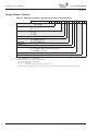
Catalog Numbering System
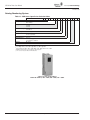
Table 1-1: VSD Series Open Drives Selection Chart
Code Number
Base Product
VS = Variable Speed Drive Prefix
Horsepower (VT) 001 = 1.0 hp to
250 = 250 hp Voltage 2 = 230V (or 208V)
4 = 480V
5 = 575V
Enclosure Rating
1 = TYPE 1
2 = TYPE 12
Enclosure Style
0 = None (Open Drive)
Revision #
A = Rev 1 (Americas)
C = Rev 1 (Canada)
V
S
0
A
-
N
0
0
0
0
Separator (–)
Communications 0 = None
N = N2/XT/SA Bus Comm (N2 by default)
L = LONWORKS® Network
Option 1
00 = None
Option 2
00 = None
All horsepower ratings are Variable Torque (VT).
3 to 200 @ 575V; 1-1/2 to 250 hp @ 480V; 1 to 100 hp @ 230V.
Voltage Ratings: 230V = 208 – 240V; 480V = 380 – 500V; 575V = 525 – 690V.
N2/XT Communications selectable on drive keypad.
SA = Sensor Actuator Bus for FEC Interface.
Johnson Controls Open Drive
TYPE 1 & TYPE 12, 208 – 240V, 380 – 500V, 525 – 690V
1-2
For more information visit: www.johnsoncontrols.com
LIT-1201828
Powered by
VSD Series Drives User Manual
Eaton Technology
November 2009
Chapter 2 — Mounting Open TYPE 1, TYPE 12 Drives
VSD Series open drives may be mounted side-by-side or stacked vertically, as outlined in the
following section.
Note: See Chapter 5 for mounting TYPE 1, TYPE 12 and TYPE 3R IntelliPass drives.
Space Requirements
To ensure proper air circulation and cooling, follow the guidelines below.
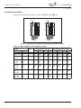
Table 2-1: Space Requirements for Mounting a VSD Series Drive
Approximate Dimensions in Inches (mm) Drive Type
Variable Torque Rating
A
230V, 1 – 3 hp
480V, 1-1/2 – 7-1/2 hp
B
C
D
0.8 (20)
0.8 (20)
3.9 (100)
2.0 (50)
230V, 5 – 10 hp
480V, 10 – 20 hp
0.8 (20)
0.8 (20)
4.7 (120)
2.4 (60)
230V, 15 – 20 hp
480V, 25 – 40 hp
575V, 3 – 30 hp
1.2 (30)
1.2 (30)
6.3 (160)
3.1 (80)
230V, 25 – 40 hp
480V, 50 – 75 hp
575V, 40 – 50 hp
3.1 (80)
3.1 (80)
11.8 (300)
3.9 (100)
230, 50 – 75 hp
480V, 100 – 150 hp
575V, 60 – 100 hp
3.1 (80)
3.1 (80)
11.8 (300)
7.9 (200)
230V, 100 hp
480V, 200 – 250 hp
575V, 125 – 200 hp
2.0 (50)
3.1 (80)
15.7 (400)
9.8 (250)
13.8 (350)
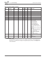
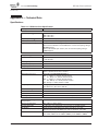
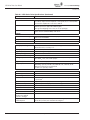
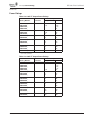
A2
5.9 (150)
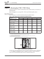
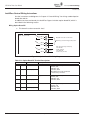
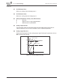
Dimensions represent the minimum clearance needed when mounting a drive. See Figure 2-1 below.
A = clearance around the VSD Series drive.
A2 = clearance needed to change the fan without disconnecting the motor cables.
B = distance between adjacent VSD Series drives or between the VSD Series drive and an enclosure wall.
C = clearance above the VSD Series drive.
D = clearance below the VSD Series drive.
Minimum clearance below the VSD Series drive needed to change the fan.
C
B
B
A
A2
A
A2
D2
Figure 2-1: Mounting Space Requirements
If several units are mounted above each other, the clearance between the drives should equal
C + D (see Table 2-1 and Figure 2-1 above). In addition, the outlet air used for cooling the
lower unit must be directed away from the inlet air used by the upper unit.
LIT-1201828
For more information visit: www.johnsoncontrols.com
2-1
VSD Series Drives User Manual
Powered by
Eaton Technology
November 2009
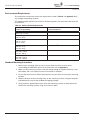
Environmental Requirements
Ensure that the environment meets the requirements listed in Table A-1 of Appendix A for
any storage or operating situation.
The following table specifies the minimum airflow required in the area where the drive will
be mounted.
Table 2-2: Cooling Airflow Requirements
Drive Type
Variable Torque Ratings
Cooling Air Required
230V, 1 – 3 hp
480V, 1-1/2 – 7-1/2 hp
41 cfm (70 m3/h)
230V, 5 – 10 hp
480V, 10 – 20 hp
112 cfm (190 m3/h)
230V, 15 – 20 hp
480V, 25 – 40 hp
575V, 3 – 30 hp
250 cfm (425 m3/h)
230V, 25 – 40 hp
480V, 50 – 75 hp
575V, 40 – 50 hp
250 cfm (425 m3/h)
230V, 50 – 75 hp
480V, 100 – 150 hp
575V, 60 – 100 hp
383 cfm (650 m3/h)
230V, 100 hp
480V, 200 – 250 hp
575V, 125 – 200 hp
765 cfm (1300 m3/h)
Standard Mounting Instructions
1. Measure the mounting space to ensure that it allows for the minimum space
surrounding the VSD Series drive. Drive dimensions are in Appendix A.
2. Make sure the mounting surface is flat and strong enough to support the drive, is not
flammable, and is not subject to excessive motion or vibration.
3. Ensure that the minimum airflow requirements for your drive are met at the mounting
location.
4. Mark the location of the mounting holes on the mounting surface, using the template
provided on the cover of the cardboard shipping package.
5. Using fasteners appropriate to your drive and mounting surface, securely attach the
drive to the mounting surface using all 4 screws or bolts.
2-2
For more information visit: www.johnsoncontrols.com
LIT-1201828
Powered by
VSD Series Drives User Manual
Eaton Technology
November 2009
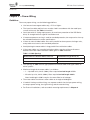
Chapter 3 — Power Wiring
Guidelines
To ensure proper wiring, use the following guidelines:
●
Use heat-resistant copper cables only, +75°C or higher.
●
The input line cable and line fuses must be sized in accordance with the rated input
current of the unit. See Tables 3-2 and 3-5.
●
Consistent with UL listing requirements, for maximum protection of the VSD Series
drive, UL recognized fuses type RK should be used.
●
If motor temperature sensing is used for overload protection, the output wire size may
be selected based on the motor specifications.
●
If three or more shielded cables are used in parallel for the output on the larger units,
every cable must have its own overload protection.
●
Avoid placing the motor cables in long parallel lines with other cables.
●
If the motor cables run in parallel with other cables, note the minimum distances
between the motor cables and other cables given in Table 3-1 below:
Table 3-1: Cable Spacings
Minimum Distance Between Cables in Feet (m)
Shielded Cable Length in Feet (m)
1 (0.3)
≤164 (50)
3.3 (1.0)
≤656 (200)
●
The spacings of Table 3-1 also apply between the motor cables and signal cables of
other systems.
●
Maximum length of the motor cables is as follows:
– 1 – 2 hp 230V units, 328 ft. (100m); filters required on lead length ≥175 ft.
– All other hp units, 984 ft. (300m); filters required on lead length ≥200 ft.
Note: Lead lengths ≥500 ft. require sine wave filter for all voltages.
LIT-1201828
●
The motor cables should cross other cables at an angle of 90 degrees.
●
If conduit is being used for wiring, use separate conduits for the input power wiring,
the output power wiring, the signal wiring, and the control wiring.
●
For Frame 4 installations, refer to conduit mounting requirements in Chapter 4.
For more information visit: www.johnsoncontrols.com
3-1
VSD Series Drives User Manual
Powered by
Eaton Technology
November 2009
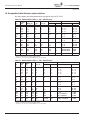
UL Compatible Cable Selection and Installation
Use only copper wire with temperature rating of at least 167°F (75°C).
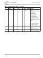
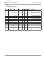
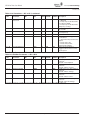
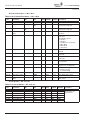
Table 3-2: Cable and Fuse Sizes — 208 – 240V Ratings Wire Size
Terminal Size
hp
Frame
Size
NEC Il (A)
Il (A)
Fuse (A) Power
Ground
Power
Ground
1
1-1/2
2
3
FR4
FR4
FR4
FR4
4.2
6
6.8
9.6
4.8
6.6
7.8
11
10
10
10
15
14
14
14
14
14
14
14
14
16 – 12
16 – 12
16 – 12
16 – 12
16 – 14
16 – 14
16 – 14
16 – 14
5
7-1/2
10
FR5
FR5
FR5
15.2
22
28
17.5
25
31
20
30
40
12
10
8
12
10
8
16 – 8
16 – 8
16 – 8
16 – 8
16 – 8
16 – 8
15
20
FR6
FR6
42
54
48
61
60
80
4
2
8
6
14 – 0
14 – 0
10 – 2
10 – 2
25
30
40
FR7
FR7
FR7
68
80
104
75
88
114
100
110
125
2
1
1/0
6
6
4
14 – 0
14 – 0
14 – 0
10 – 00
10 – 00
10 – 00
50
60
75
FR8
FR8
FR8
130
154
192
140
170
205
175
200
250
3/0
4/0
300
2
0
2/0
4-3/0
000-350 MCM
000-350 MCM
4-000
4-000
4-000
100
FR9
248
261
300
2 x 4/0
3/0
2*000-350 MCM
4-000
If power cubes are used, a UL recognized RK fuse is recommended.
Based on maximum environment of 104°F (40°C).
If bypass is used, a UL recognized RK5 fuse is recommended.
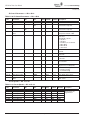
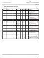
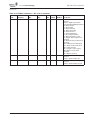
Table 3-3: Cable and Fuse Sizes — 380 – 500V Ratings Terminal Size
Frame
Size
NEC Il
(A)
Il
(A)
Fuse (A) Power
Ground
Power
Ground
1-1/2
2
3
5
7-1/2
FR4
FR4
FR4
FR4
FR4
3
3.4
4.8
7.6
11
3.3
4.3
5.6
7.6
12
10
10
10
10
15
14
14
14
14
12
14
14
14
14
14
16 – 12
16 – 12
16 – 12
16 – 12
16 – 12
16 – 14
16 – 14
16 – 14
16 – 14
16 – 14
10
15
20
FR5
FR5
FR5
14
21
27
16
23
31
20
30
35
10
10
8
12
10
8
16 – 8
16 – 8
16 – 8
16 – 8
16 – 8
16 – 8
25
30
40
FR6
FR6
FR6
34
40
52
38
46
61
50
60
80
6
4
2
8
8
6
14 – 0
14 – 0
14 – 0
10 – 2
10 – 2
10 – 2
50
60
75
FR7
FR7
FR7
65
77
96
72
87
105
100
110
125
2
1
1/0
6
6
4
14 – 0
14 – 0
14 – 0
10 – 00
10 – 00
10 – 00
100
125
150
FR8
FR8
FR8
124
156
180
140
170
205
175
200
250
3/0
4/0
300
2
0
2/0
4 – 3/0
000 – 350 MCM
000 – 350 MCM
4 – 000
4 – 000
4 – 000
200
250
FR9
FR9
240
302
261
300
350
400
350
2 X 250
3/0
300
2*000 – 350 MCM
2*000 – 350 MCM
4 – 000
4 – 000
3-2
Wire Size
hp
If power cubes are used, a UL recognized RK fuse is recommended.
Based on maximum environment of 104°F (40°C).
If bypass is used, a UL recognized RK5 fuse is recommended.
For more information visit: www.johnsoncontrols.com
LIT-1201828
Powered by
VSD Series Drives User Manual
Eaton Technology
November 2009
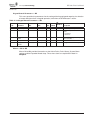
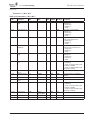
Table 3-4: Cable and Fuse Sizes — 525 – 690V Ratings Wire Size
Terminal Size
hp
Frame
Size
Il
(A)
Fuse (A) Power
Ground
Power
Ground
3
5
7-1/2
10
FR6
FR6
FR6
FR6
4.5
7.5
10
13.5
10
10
10
15
14
14
14
12
14
14
14
14
14 – 0
14 – 0
14 – 0
14 – 0
14 – 2
14 – 2
14 – 2
14 – 2
15
20
25
30
FR6
FR6
FR6
FR6
18
22
27
34
20
30
35
40
10
10
8
8
12
10
8
8
14 – 0
14 – 0
14 – 0
14 – 0
14 – 2
14 – 2
14 – 2
14 – 2
45
50
FR7
FR7
41
52
50
60
6
4
8
6
14 – 0
14 – 0
10 – 0
10 – 0
60
75
100
FR8
FR8
FR8
62
80
100
80
100
125
2
1
1/0
6
6
6
4 – 3/0
4 – 3/0
4 – 3/0
4 – 3/0
4 – 3/0
4 – 3/0
125
150
200
FR9
FR9
FR9
125
144
208
175
200
250
3/0
4/0
350
6
2
1/0
4 – 3/0
2x3/0 – 350 MCM
2x3/0 – 350 MCM
4 – 3/0
4 – 3/0
4 – 3/0
If power cubes are used, a UL recognized RK fuse is recommended.
Based on maximum environment of 104°F (40°C).
If bypass is used, a UL recognized RK5 fuse is recommended.
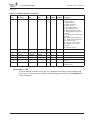
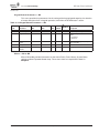
Table 3-5: Maximum Symmetrical Supply Current
Product
Voltage
Maximum RMS Symmetrical Amperes on Supply Circuit
1 – 75 hp
230
100,000A
1-1/2 – 250 hp
480
100,000A
3 – 200 hp
575
100,000A
Table 3-6: Power Connection Tightening Torque
Rating
Frame Size
Tightening Torque
(in-lbs)
Tightening Torque
(Nm)
230V, 1 – 3 hp
480V, 1-1/2 – 7-1/2 hp
230V, 5 – 10 hp
480V, 10 – 20 hp
230V, 15 – 20 hp
480V, 25 – 40 hp
575V, 3 – 30 hp
230V, 25 – 40 hp
480V, 50 – 75 hp
575V, 40 – 50 hp
230, 50 – 75 hp
480V, 100 hp
FR4
5
0.6
FR5
13
1.5
FR6
35
4
FR7
88
10
FR8
170/80 20/9 480V, 125 – 150 hp
575V, 60 – 100 hp
FR8
354/195 40/22 230V, 100 hp
480V, 200 – 250 hp
575V, 125 – 200 hp
FR9
354/195 40/22 LIT-1201828
The isolation standoff of the bus bar will not withstand the listed tightening torque. Use a wrench to apply a counter torque when
tightening.
For more information visit: www.johnsoncontrols.com
3-3
VSD Series Drives User Manual
Powered by
Eaton Technology
November 2009
Installation Instructions
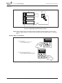
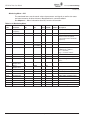
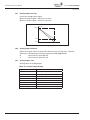
Strip the motor and power cables as shown in Figure 3-1 and Table 3-7.
Ground
Ground
A1
C1
A2
C2
B1
D1
B2
D2
Power
Motor
Figure 3-1: Input Power and Motor Cable Stripping and Wire Lengths
Table 3-7: Power and Motor Cable Stripping Lengths
Product
Horsepower Voltage
3-4
Frame
Size
Power Wiring in Inches (mm)
Motor Wiring in Inches (mm)
A1
B1
C1
D1
A2
B2
C2
D2
1–3
1-1/2 – 7-1/2
230
480
FR4
0.59
(15)
1.38
(35)
0.39
(10)
0.79
(20)
0.28
(7)
1.97
(50)
0.28
(7)
1.38
(35)
5 – 10
10 – 20
230
480
FR5
0.79
(20)
1.57
(40)
0.39
(10)
1.18
(30)
0.79
(20)
2.36
(60)
0.39
(10)
1.57
(40)
15 and 20
25 – 40
3 – 30
230
480
575
FR6
0.79
(20)
3.54
(90)
0.59
(15)
2.36
(60)
0.79
(20)
3.54
(90)
0.59
(15)
2.36
(60)
25 – 40
50 – 75
40 – 50
230
480
575
FR7
0.98
(25)
4.72
(120)
0.98
(25)
4.72
(120)
0.98
(25)
4.72
(120)
0.98
(25)
4.72
(120)
50 – 75
100 – 150
60 – 100
230
480
575
FR8
1.1
(28)
9.45
(240)
1.1
(28)
9.45
(240)
1.1
(28)
9.45
(240)
1.1
(28)
9.45
(240)
100
200 – 250
125 – 200
230
480
575
FR9
1.1
(28)
11.61
(295)
1.1
(28)
11.61
(295)
1.1
(28)
11.61
(295)
1.1
(28)
11.61
(295)
For more information visit: www.johnsoncontrols.com
LIT-1201828
Powered by
VSD Series Drives User Manual
Eaton Technology
November 2009
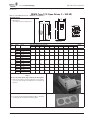
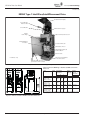
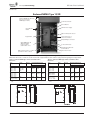
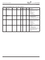
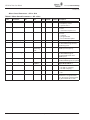
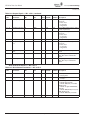
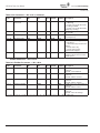
NEMA Type 1/12 Open Drives (1 – 250 HP)
Table 3-8: Control Wiring Instructions — NEMA Type 1/12 Open Drives
Mounting Drive
W1
W2
1. Mount Drive
(See Table below for dimensions.)
R2
D1
R1
D2
H1
H2
H3
D3
R2
Knockouts
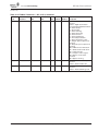
Figure 3-2:
VSD Series Open Drive Dimensions
Frame
Size
FR4
FR5
FR6
FR7
FR8
FR9
FR10
Voltage
hp (VT)
230V
3/4 – 3
480V
1–5
230V
5 – 7-1/2
480V
7-1/2 – 15
230V
10 – 15
480V
20 – 30
575V
2 – 25
230V
20 – 30
480V
40 – 60
575V
30 – 40
480V
75 – 125
575V
50 – 75
480V
150 – 200
575V
100 – 150
480V
250 – 350
575V
200 – 300
Approximate Dimensions in Inches (mm)
Weight
Lbs. (kg)
H1
H2
H3
D1
D2
D3
W1
W2
R1 dia.
R2 dia.
12.9
(327)
12.3
(313)
11.5
(292)
7.5
(190)
2.5
(64)
5.0
(126)
5.0
(128)
3.9
(100)
.5
(13)
.3
(7)
11
(5)
16.5
(419)
16.0
(406)
15.4
(391)
8.4
(214)
2.7
(68)
5.8
(148)
5.7
(144)
3.9
(100)
.5
(13)
.3
(7)
17.9
(8.1)
22.0
(558)
21.3
(541)
20.4
(519)
9.3
(237)
2.7
(68)
6.7
(171)
7.7
(195)
5.8
(148)
.7
(18)
.4
(9)
40.8
(18.5)
24.8
(630)
24.2
(614)
23.3
(591)
10.1
(257)
2.7
(68)
7.5
(189)
9.3
(237)
7.5
(190)
.7
(18)
.4
(9)
77.2
(35)
29.7
(755)
28.8
(732)
28.4
(721)
11.3
(288)
1.3
(34)
11.0
(279)
11.2
(285)
10.0
(255)
.7
(18)
.4
(9)
127.8
(58)
45.3
(1150)
44.1
(1120)
—
14.3
(362)
5.4
(137)
8.8
(224)
18.9
(480)
15.7
(400)
.7
(18)
.4
(9)
321.9
(146)
44
(1120)
33.5
(850)
—
23.6
(600)
NA
NA
23.6
(600)
16.7
(425)
.9
(23)
.47
(12)
550.7
(250)
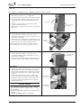
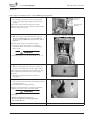
Power Wiring
Notice
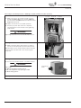
Do not discard the plastic bag containing the wiring plate.
2. Remove the bottom cover by rotating the cover toward
you on the base hinges, then lifting the cover away from
the base.
Power Wiring
3. Locate the plastic bag shipped with the drive containing
the wiring plate, and remove the wiring plate.
LIT-1201828
For more information visit: www.johnsoncontrols.com
3-5
VSD Series Drives User Manual
Powered by
Eaton Technology
November 2009
Standard Wiring Diagrams and Terminal Locations
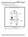
Power and Motor Wiring Terminal Schematics for VSD Series Drives
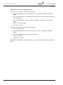
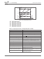
The following wiring diagrams show the line and motor connections of the drive.
Power
Board
VT
230V
480V
575V
1 - 20 hp
1-1/2 - 40 hp
3 - 30 hp
Control
Board
L1
L2
B+
L3
R- U
V
W
B-
Note:
Integrated Brake
Chopper Circuit Not
Included on 575V units.
R+
Brake
Option
L1 L2 L3
See
Note
(Line)
Separate Conduit
Motor
3~
(Load)
Separate Conduit
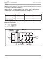
Figure 3-3: Principle Wiring Diagram of VSD Series Power Unit,
FR4, FR5 and FR6
Note: When using a 1-phase supply, for units rated for such, connect the input power to
terminals L1 and L2. Refer to Tables A-2 and A-3 in Appendix A.
3-6
For more information visit: www.johnsoncontrols.com
LIT-1201828
Powered by
VSD Series Drives User Manual
Eaton Technology
November 2009
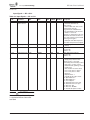
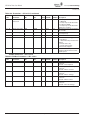
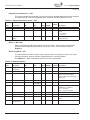
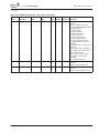
Table 3-8: Control Wiring Instructions — NEMA Type 1/12 Open Drives (Continued)
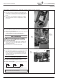
Power Wiring
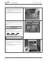
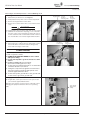
4. If conduit is being used, attach the wiring plate to it.
5. Pass the motor and input power wires/cables through the
holes of the wiring plate.
6. If shielded cable is used, connect the shields of the input
line power cable and the motor cable to the motor and
power ground terminals of the VSD Series drive.
Power Wiring/Grounding
7. Wire power terminals, motor terminals, and grounding
terminals per diagram. Power and Motor leads must be in
separate conduit.
Note: Do not wire motor loads to B- B+ R-. This will cause
damage.
GROUND WIRING
●
●
●
●
Run motor cables in separate conduit.
DO NOT RUN CONTROL WIRES in same conduit
Cables sized per NEC.
Provide low impedance ground between drive and
motor.
Utility
Drive
Motor Ground
(Inside Motor Conduit Box)
IMPORTANT: Improper grounding could result in damage to the
motor and/or drive and could void warranty
Control Wiring
8. Wire the control terminals following the details for the
specific option boards shown on the following pages.
Note: For ease of access, the option board terminal blocks can
be unplugged for wiring.
Note: If using conduit or Seal Tite for control wiring for Frame
4, you must order NEMA Type 12 kit.
LIT-1201828
For more information visit: www.johnsoncontrols.com
3-7
VSD Series Drives User Manual
Powered by
Eaton Technology
November 2009
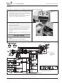
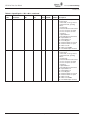
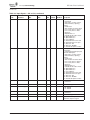
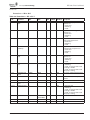
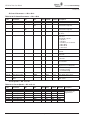
Table 3-8: Control Wiring Instructions — NEMA Type 1/12 Open Drives (Continued)
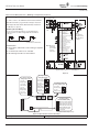
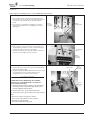
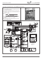
Control Wiring
Incoming Power
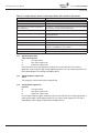
9. Wire control to the OPTA9 Control Board and OPTA2.
Note: Drive default is programmed for Damper Interlock.
Note: Option Boards OPTC2 (N2/XT/SA Bus) and OPTC4
(LonWorks) are optional.
Optional
CB
Mandatory Ground Wiring
Be sure to pull low impendance ground wiring from
customer power to drive and ground wire from drive
to motor.
Utility
Drive
Motor Ground
(Inside Motor Conduit Box)
Note: Must pull
dedicated
ground wire
to drive
and motor.
I/O Connection
●
●
●
Run 110 Vac and 24 Vdc Control wiring in separate
conduit.
Communication wire to be shielded.
RS-232 Keypad cable less than 20 feet.
1
2
3
4
5
6
7
8
9
10
11
12
13
14
15
16
17
18
19
20
+1DV
Vin+
GND
Lin+
Lin–
24Vout
GND
DIN1
DIN2
DIN3
CMA
24Vout
GND
DIN4
DIN5
DIN6
CMB
Lout+
Lout–
DO1
Reference Output
X1
A
B
C
D
Analog Input Voltage
(Range 0-10V DC)
I/O Ground
Analog Input Current
(Range 4-20mA)
X2
A
B
C
D
Control Voltage Output
X3
I/O Ground
Start/Stop
External Fault
Run Permisive Damper Interlock
DIN1-DIN3 Common
Control Voltage Output
I/O Ground
Speed Select 1
Fire Mode
Bypass Overload Fault
DIN4-DIN6 Common
X6
A
Output Frequency
B
C
Analog Output
D
Digital Output Ready
Note:
See Figure 3
for Dip X1, X2,
X3, X6 Switch
settings.
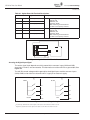
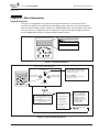
Note: Optional Communication Cards can be
supplied with the Drive or as a Field Option.
Figure 3-4:
X1 Jumper Setting
Analog Input 1 (AI1)
ABC D
0 to 10V*
Voltage Input
ABC D
0 to 20 mA
Current Input
0 to 10V
ABC D
(Differential)
Voltage Input
-10 to 10V
Voltage Input
ABC D
X2 Jumper Setting
Analog Input 2 (AI2)
0 to 20 mA* A B C D
Current Input
ABC D
0 to 10V
Voltage Input
X6 Jumper Setting
Analog Output 1 (A01)
0 to 10V
ABC D
(Differential)
Voltage Input
ABC D
0 to 20 mA*
Current Output
ABC D
-10 to 10V
Voltage Input
ABC D
0 to 10V
Voltage Output
ABC D ABC D
X1
X2
ABC D
X6
X3 Jumper Setting
CMA and CMB Grounding
CMB Connected to Ground*
CMA Connected to Ground
X3
CMB Isolated from Ground
CMA Isolated from Ground
CMB and CMA Internally
Connected and Isolated
from Ground
* Designates Default Jumper Settings
Figure 3-5: Option Board A9 Location and Settings
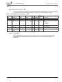
Start-Up Wizard
3-8
See Page 7-4, Start-Up Wizard
For more information visit: www.johnsoncontrols.com
LIT-1201828
Powered by
VSD Series Drives User Manual
Eaton Technology
November 2009
Checking the Cable and Motor Insulation
1. Check the motor cable insulation as follows:
●
Disconnect the motor cable from terminals U, V and W of the VSD Series drive and
from the motor.
●
Measure the insulation resistance of the motor cable between each phase conductor
as well as between each phase conductor and the protective ground conductor.
●
The insulation resistance must be >1MΩ.
2. Check the input power cable insulation as follows:
●
Disconnect the input power cable from terminals L1, L2 and L3 of the VSD Series
drive and from the utility line feeder.
●
Measure the insulation resistance of the input power cable between each phase
conductor as well as between each phase conductor and the protective ground
conductor.
●
The insulation resistance must be >1MΩ.
3. Check the motor insulation as follows:
LIT-1201828
●
Disconnect the motor cable from the motor and open any bridging connections in
the motor connection box.
●
Measure the insulation resistance of each motor winding. The measurement voltage
must equal at least the motor nominal voltage but not exceed 1000V.
●
The insulation resistance must be >1MΩ.
For more information visit: www.johnsoncontrols.com
3-9
VSD Series Drives User Manual
Powered by
Eaton Technology
November 2009
3-10
For more information visit: www.johnsoncontrols.com
LIT-1201828
Powered by
VSD Series Drives User Manual
Eaton Technology
November 2009
Chapter 4 — Control Wiring
General Information
The control unit of the VSD Series drive consists of the control board and various option
boards that plug into the five slot connectors (A to E) of the control board.
Galvanic isolation of the control terminals is provided as follows:
●
Control connections are isolated from power, and the GND terminals are permanently
connected to ground.
●
Digital inputs are galvanically isolated from the I/O ground.
●
Relay outputs are double-isolated from each other at 300V AC.
Option Board General Information
The VSD Series drives can accommodate a wide selection of expander and adapter boards to
customize the drive for your application needs.
The drive’s control unit is designed to accept a total of five option boards. Option boards are
available for normal analog and digital inputs and outputs, for communication and for
additional application-specific hardware.
The VSD Series factory installed standard option board configuration includes an A9 I/O
board and an A2 relay output board, which are installed in slots A and B. For information on
additional option boards, see the VSD Series drives option board manuals.
Note: If your VSD Series drive has been shipped with a factory installed IntelliPass bypass,
the B5 option board is installed in slot C.
B
C
D
E
A
Figure 4-1: Option Board Slots
LIT-1201828
For more information visit: www.johnsoncontrols.com
4-1
VSD Series Drives User Manual
Powered by
Eaton Technology
November 2009
Table 4-1: Option Board A2 Terminal Descriptions
Terminal
Signal
Description and Parameter Reference
Run
Switching Capacity:
24V DC / 8A
250V AC / 8A
125V DC / 0.4Az
Min switching load: 5V/10 mA
Continuous Capacity: <2 Arms
Fault
Switching Capacity:
24V DC / 8A
250V AC / 8A
125V DC / 0.4A
Min switching load: 5V/10 mA
Continuous Capacity: <2 Arms
21
RO-1/1
Normally Closed (NC)
22
RO-1/2
Common
23
RO-1/3
Normally Open (NO)
24
RO-2/1
Normally Closed (NC)
25
RO-2/2
Common
26
RO-2/3
Normally Open (NO)
21 22 23
24 25 26
Figure 4-2: Option Board A2 Terminal Locations
Inverting the Digital Input Signal
The active signal level depends on which potential the common inputs CMA and CMB
(terminals 11 and 17) are connected to. The alternatives are either 24V DC or ground (0V). See
Figure 4-3.
The 24V DC control voltage and the ground for the digital inputs and the common inputs
(CMA, CMB) can be either the internal 24V DC supply or an external supply.
1
2
24V DC
Ground
Ground
DI-1
DI-1
DI-2
DI-2
DI-3
DI-3
CMA
+24V
CMA
Figure 4-3: Positive/Negative Logic
4-2
Positive logic (24V DC is the active signal) = the input is active when the switch is closed.
Negative logic (0V is the active signal) = the input is active when the switch is closed.
For more information visit: www.johnsoncontrols.com
LIT-1201828
Powered by
VSD Series Drives User Manual
Eaton Technology
November 2009
Chapter 5 — IntelliPass Bypass Option
Product Description
The Johnson Controls VSD Series IntelliPass Drive is powered by the Cutler-Hammer®
tradition of providing a premier intelligent drive integrated with a reliable bypass
configuration, by taking advantage of the enclosed control and circuit breaker expertise of
Eaton’s electrical business.
The IntelliPass bypass is a two- or three-contactor design utilizing the Cutler-Hammer
24V DC series of contactors and power supplies. The features, function and form allow the
drive and bypass to become an integrated design, enabling Johnson Controls to introduce
the world’s smallest drive and bypass package. The IntelliPass drive comes standard with a
Cutler-Hammer protective disconnect integrated into the drive and bypass design.
IntelliPass 2 & 3 Contactor
Bypass Drive
208V, 1-1/2 – 60 hp
230V, 1 – 75 hp
480V, 1 – 150 hp
575V, 3 – 100 hp
208V, 1 – 30 hp
230V, 1 – 30 hp
480V, 1 – 75 hp
IntelliPass TYPE 3R, 2 & 3 Contactor
Bypass Drive
208V, 1-1/2 – 60 hp
230V, 1 – 75 hp
480V, 1 – 150 hp
575V, 3 – 100 hp
LIT-1201828
IntelliPass TYPE 12, 2 & 3 Contactor
Bypass Drive
DX-9100 TYPE 1, 2 & 3 Contactor
Bypass Drive
208V, 1-1/2 – 60 hp
230V, 1 – 75 hp
480V, 1 – 150 hp
575V, 3 – 100 hp
For more information visit: www.johnsoncontrols.com
5-1
VSD Series Drives User Manual
Powered by
Eaton Technology
November 2009
Catalog Number Selection
Table 5-1: VSD Series IntelliPass/IntelliDisconnect Drives Selection Chart
Base Product
Code Number
VS = Variable Speed
Drive Prefix
V
S
1
1
A
-
N
Horsepower (VT) 001 = 1.0 hp to
075 = 75 hp Voltage
1 = 208V
2 = 230V
4 = 480V
Enclosure Rating
Enclosure Style
1 = TYPE 1
1 = IntelliPass
4 = IntelliDisconnect
Revision #
A = Rev 1 (Americas)
Separator (–)
Communications 0 = None
N = N2/XT/SA Bus Comm (N2 by default)
L = LONWORKS® Network
Option 1
See Options List Option 2
See Options List 5-2
All horsepower ratings are Variable Torque (VT).
1 – 30 hp 208/230V AC; 1 – 75 hp 480V AC
N2/XT Communications selectable on drive keypad.
SA = Sensor Actuator Bus for FEC Interface.
Options List: 00 = None
P6 = 3rd Contactor Drive Isolation (IntelliPass only)
Note: All VSD Series IntelliPass Drives incorporate two factory installed Auxiliary Contacts (formerly the “K9” option).
For more information visit: www.johnsoncontrols.com
LIT-1201828
Powered by
VSD Series Drives User Manual
Eaton Technology
November 2009
Table 5-2: VSD Series Enclosed Drives Selection Chart
Base Product
Horsepower (VT) Voltage
Enclosure Rating
Enclosure Style
Revision Number
Separator (–)
Communications Option 1
Option 2
Code Number
V S
VS = Variable Speed Drive
Prefix
001 = 1.0 hp to
150 = 150 hp 1 = 208V
2 = 230V
4 = 480V
5 = 575V
1 = TYPE 1
2 = TYPE 12
3 = TYPE 3R
2 = Enclosed IntelliPass
3 = Enclosed Drive w/Disconnect (IntelliDisconnect)
A = Rev 1 (Americas)
-
0 = None
N = N2/XT/SA Bus Comm (N2 by default)
L = LONWORKS® Network
See Options List
See Options List
All horsepower ratings are Variable Torque (VT).
1 to 60 hp @ 208V; 1 to 75 hp @ 230V; 1 to 150 hp @ 480V; 3 to 100 hp @ 575V
N2/XT/SA Communications selectable on drive keypad.
SA = Sensor Actuator Bus for FEC Interface.
Table 5-3: Options List
Option
Description
00
P3
None
Line Fuses (formerly Drive Isolation Fusing) — Provides high-level fault protection of the
input power circuit from the load side of the fuses to the input side of the power transistors.
The option consists of three 200 kA fuses, which are factory mounted in the enclosure.
Third Contactor Drive Isolation — Provides load side isolation to the drive in the event of an
SCR or DC Bus failure, allowing the drive to go into bypass without tripping the circuit
breaker. Typically used in critical applications or when required in a specification.
Line Fuses & Third Contactor
Space Heater w/Transformer — Prevents condensation from forming in the enclosure when
the drive is inactive or in storage. Includes a thermostat for variable temperature control.
P6 P9 SA
IntelliPass only.
Table 5-4: Option Notes
All VSD Series IntelliPass Drives incorporate two factory-installed Auxiliary Contacts
(formerly the K9 option).
P3
Line Fuses
Line Fuses, on load side of breaker in both drive and bypass modes
Always included in the part number for 575V Enclosed IntelliPass Drives
P9
Line Fuses &
Mutually exclusive from Option P3 (Line Fuses) in 575V Enclosed
Third Contactor IntelliPass Drives
SA
Space Heater
Only available for TYPE 3R (Enclosure Rating 3).
w/Transformer
LIT-1201828
For more information visit: www.johnsoncontrols.com
5-3
VSD Series Drives User Manual
Powered by
Eaton Technology
November 2009
NEMA Type 1 IntelliPass/IntelliDisconnect Drive
Circuit Breaker Endplate
Circuit Breaker
Extension Bar
Circuit Breaker
24V DC Power Supply *
Ribbon
Cable Hinge
Optional 3rd Input Contactor *
Output & Bypass
Contactor*
Contactor Overload *
Manual/Auto Reset *
24V DC Motor Overload
Terminal Block *
Ground Studs
* IntelliPass only.
Drive Enclosure Endplate
(located at bottom)
Optional 3rd Contactor S1 Switch *
(provided for drive isolation)
Figure 5-1: Identification of NEMA Type 1 Components
Table 5-5: VSD Series NEMA Type 1 IntelliPass/IntelliDisconnect Drive
Dimensions
Drive
Horsepower (VT)
Frame
Size
Approximate
Dimensions in
Inches (mm)
Approx.
Weight
in lbs. (kg)
A
B
C
Distance
Between
Drives in
Inches (mm) D
208V, 1 – 3 hp
230V, 1 – 3 hp
480V, 1 – 7-1/2 hp
FR4
5.04
(128)
18.25
(464)
13.24
(336)
21 (9.5)
5.3 (134.6)
208V, 5 – 7-1/2 hp
230V, 5 – 10 hp
480V, 10 – 20 hp
FR5
5.50
(140)
23.25
(591)
13.24
(336)
35 (15.9)
5.7 (144.8)
208V, 10 – 20 hp
230V, 15 and 20 hp
480V, 25 – 40 hp
FR6
7.50
(191)
29.38
(746)
15.25
(387)
67 (30.4)
7.5 (190.5)
208V, 25 and 30 hp
230V, 25 and 30 hp
480V, 50 – 75 hp
FR7
9.10
(231)
37.53
(953)
15.25
(387)
108 (49.0)
9.0 (228.6)
If mounting two or more IntelliPass Drives next to each other, make sure to use the
proper spacing between the drives for hinged door operation.
Figure 5-2: VSD Series IntelliPass/IntelliDisconnect Drive Dimensions
5-4
For more information visit: www.johnsoncontrols.com
LIT-1201828
Powered by
VSD Series Drives User Manual
Eaton Technology
November 2009
Table 5-6: Bypass Power Wiring Instructions — NEMA Type 1 IntelliPass/IntelliDisconnect Drive
Mounting Drive
1. Mount drive per dimensions. (See Page 5-4)
2. Verify that the main power source is removed upstream.
3. Using a flat-blade screwdriver, remove the four screws
securing the outer cover of the drive and remove the
cover.
4. Using the same screwdriver, remove the two center
screws securing the side cover.
5. Make sure there is adequate room, and open the hinged
side cover.
Outer Cover
Two Screws on
Side Cover
Power Wiring
6. Using a flat-blade screwdriver, remove the screws
securing the endplate at the bottom of the drive enclosure,
and remove the endplate.
7. Using a Greenlee conduit cutter (recommended), cut one
or more holes in the endplate, located at the bottom of the
drive’s enclosure, for the motor and power leads.
Bottom
Endplate
Note: If bringing the power leads in through the top of the
drive’s enclosure, go to step 8. If not, proceed to step 10.
Power Wiring
8. Using a flat-blade screwdriver, remove the screws
securing the endplate for the circuit breaker enclosure,
and remove the endplate.
9. Using a Greenlee conduit cutter (recommended), cut one
hole in the circuit breaker endplate for the power leads.
Power Wiring
10. Calibrate the circuit breaker amperage, so it is 1.25 times
the amperage on the motor nameplate, by turning the
red set screw located below the circuit breaker extension
bar. See the circuit breaker user’s manual supplied with
the drive.
11. Connect the incoming power leads to circuit breaker
terminals labeled L1, L2 and L3. Cables sized per NEC.
12. Using the torque wrench, tighten each terminal to the
torque value found in the appropriate user’s manual
supplied with the drive.
POWER WIRING
●
●
●
●
Run cabling in separate metal conduit or wiring tray.
DO NOT RUN CONTROL WIRING with incoming
power wiring.
Provide low impedance ground connection to drive
chassis.
DO NOT CONNECT to B+, B-, R terminals.
LIT-1201828
Circuit Breaker
Endplate
Incoming
Power Leads
Circuit Breaker
Terminals
Circuit Breaker
Set Screw
Circuit Breaker
Extension Bar
For more information visit: www.johnsoncontrols.com
5-5
VSD Series Drives User Manual
Powered by
Eaton Technology
November 2009
Table 5-6: Bypass Power Wiring Instructions — NEMA Type 1 IntelliPass/IntelliDisconnect Drive (Continued)
Motor Wiring
13. Use your first and second fingers and simultaneously
push down to release the two orange retaining clips (one
on each side of the 24V DC motor overload terminal
block).
14. If necessary, use a flat-blade screwdriver to carefully
remove the terminal block in a straight plane to avoid
damaging it.
Motor Wiring
15. Connect the motor leads to the motor overload terminals
labeled 1TA, 1TB and 1TC.
16. Using the appropriate metric Allen wrench (2.5 mm, 3 mm
or 4 mm), tighten each overload terminal per the
specifications in the contactor user’s manual.
MOTOR WIRING
Motor
Overload
Terminals
Motor
Leads
An SAE allen wrench will damage the terminals,
and the motor overload will need to be replaced
(not covered by warranty).
17. Using the torque wrench, tighten each terminal to the
torque value found in the appropriate user’s manual
supplied with the drive.
18. Reinsert the motor overload terminal block.
Grounding
19. Use a flat-blade screwdriver to connect the motor ground
wire to the ground stud (located at either the top or
bottom of the drive’s enclosure). (Mandatory) Ground
connection main power ground must be connected to
other ground screws.
Motor
Ground
Stud
GROUND WIRING
●
●
●
●
Run motor cables in separate conduit.
DO NOT RUN CONTROL WIRES in same conduit
Cables sized per NEC.
Provide low impedance ground between drive and
motor.
Utility
Drive
Motor Ground
(Inside Motor Conduit Box)
IMPORTANT: Improper grounding could result in damage to the
motor and/or drive and could void warranty
5-6
For more information visit: www.johnsoncontrols.com
LIT-1201828
Powered by
VSD Series Drives User Manual
Eaton Technology
November 2009
Table 5-6: Bypass Power Wiring Instructions — NEMA Type 1 IntelliPass/IntelliDisconnect Drive (Continued)
Setting Overload
Auto/Manual
Reset
20. Lift to open the cover on the motor overload, and use a
1/8" flat-blade screwdriver to set the overload amperage to
match the value on the motor nameplate.
21. Turn the auto/manual reset (factory default is manual) on
the motor overload 90° to the auto position.
Control Wiring
22. Use a flat-blade screwdriver to carefully remove the lowvoltage I/O terminal block.
23. Insert the incoming control leads into the terminal block.
Refer to the electrical schematic supplied with the drive.
24. Reinsert the I/O terminal block into the control board.
25. Verify that all other wires to the terminal block are
connected.
26. Terminate control wiring to the OPTA9 and OPTA2 board
(Terminals 1 – 26).
CONTROL WIRING
●
●
●
Run 110 Vac and 24 Vdc control wiring in separate
conduit.
Communication wire must be shielded.
RS-232 keypad cable must be less then 25 feet.
Drive
Ground
Optional
Customer
Ground
Motor
Ground
Note: See Figure 3
for Dip X1, X2,
X3, X6 Switch
settings.
Optional
Drive
Ground
Start/Stop
Speed Select 1
Fire Mode
Bypass Overload Fault
Note: Optional COMM cards can be supplied
Note: with the drive or as a field option.
Figure 5-3: VSD Series IntelliPass with Three Contactors
LIT-1201828
For more information visit: www.johnsoncontrols.com
5-7
VSD Series Drives User Manual
Powered by
Eaton Technology
November 2009
Table 5-6: Bypass Power Wiring Instructions — NEMA Type 1 IntelliPass/IntelliDisconnect Drive (Continued)
Static Check
L1, L2, L3
B-, B+, BT
T1, T2, T3
27. Make sure power is off, and perform static checks as
described in Table 5-10 (for the converter), Table 5-11
(for the inverter) and Table 5-12 (for the DC bus). Refer to
Page 5-14, Static Check.
Note: Static check shown is for L3 and B+ terminals.
28. Once the pre-power static checks are completed,
reinstall the drive’s outer and side covers, tightening
all the screws.
WARNING
High Voltage is present on L1, L2, L3, B-, B+, BT, T1, T2, T3.
Starting Drive
29. Make sure that the drive’s 3rd contactor S1 switch, if
present, is in the ON position (shown in OFF position).
Note: The bypass mode operates with the switch in the OFF
position, however the drive will not run. Yet the keypad
will operate.
Starting Drive
30. Turn the circuit breaker handle in a clockwise direction.
WARNING
Circuit Breaker
Handle
High Voltage
●
●
●
Always work with another person.
Be sure equipment is properly grounded.
Wear safety glasses.
Start-Up Wizard
5-8
See Page 7-4, Start-Up Wizard
For more information visit: www.johnsoncontrols.com
LIT-1201828
Powered by
VSD Series Drives User Manual
Eaton Technology
November 2009
Enclosed NEMA Type 12/3R
Optional NEMA Type 3R Hood
(Hood not present on
NEMA Type 12 drive)
Power Ground Stud
Circuit Breaker
24V DC Power Supply
Circuit Breaker
Handle
Optional 3rd Input Contactor
Space Heater (not on
electrical schematic)
Keypad Cable
Output & Bypass Contactor
50 hp NEMA Type 3R
480V AC Variable
Frequency Drive
(behind drive cover)
Contactor Overload
24V DC Motor Overload
Terminal Block
Optional 3rd Contactor S1 Switch
(provided for drive isolation)
Motor Ground Stud
Figure 5-4: Identification of NEMA Type 12 and NEMA Type 3R Components
Note: You will need to consult the electrical schematic supplied with the drive and the appropriate wiring diagram in Appendix D.
Table 5-7: VSD Series NEMA Type 12 Enclosed IntelliPass Drive
Dimensions
Drive
Horsepower (VT)
Frame
Size
Enclosure
Box
Table 5-8: VSD Series NEMA Type 3R Enclosed IntelliPass Drive
Dimensions
Approximate Dimensions in
Inches (mm)
A
B
C
208V, 1 – 15 hp
230V, 1 – 15 hp
480V, 1 – 30 hp
575V, 3 – 30 hp
FR4 – FR6
FR4 – FR6
FR4 – FR6
FR6
A
16.92
(429.8)
29.00
(736.6)
18.60
(472.4)
208V, 20 – 30 hp
230V, 20 – 30 hp
480V, 40 – 75 hp
575V, 40 – 50 hp
FR6 – FR7
B
20.92
(531.3)
40.00
(1016.0)
19.10
(485.1)
208V, 40 – 60 hp
230V, 40 – 60 hp
480V, 100 – 150 hp
FR8
C
30.92
(785.3)
52.00
(1320.8)
19.10
(485.1)
Floor Stands available on Box C only and can be purchased and shipped separately
as kit.
Drive
Horsepower (VT)
Frame
Size
Enclosure
Box
Approximate Dimensions in
Inches (mm)
A
B
C
208V, 1 – 15 hp
230V, 1 – 15 hp
480V, 1 – 30 hp
575V, 3 – 30 hp
FR4 – FR6
A
21.05
(534.7)
33.00
(838.2)
19.57
(497.0)
208V, 20 – 30 hp
230V, 20 – 30 hp
480V, 40 – 75 hp
575V, 40 – 50 hp
FR6 – FR7
B
26.31
(668.3)
46.09
(1170.7)
20.07
(509.9)
208V, 40 – 60 hp
230V, 40 – 60 hp
480V, 100 – 150 hp
FR8
C
37.73
(958.3)
58.09
(1475.5)
20.08
(510.0)
Floor Stands available on Box C only and can be purchased and shipped separately
as kit.
NEMA Type 12
Figure 5-5: VSD Series Enclosed Drive Dimensions
LIT-1201828
For more information visit: www.johnsoncontrols.com
5-9
VSD Series Drives User Manual
Powered by
Eaton Technology
November 2009
Table 5-9: Bypass Power Wiring Instructions — Enclosed NEMA Type 12/3R
Mounting Drive
1.
2.
3.
4.
Keypad Cable
Mount drive per dimensions. (See Page 5-9.)
Verify that the main power source is removed upstream.
Remove the keypad cable from the drive.
Remove the screws from the drive cover, and remove the
cover.
Circuit
Breaker
Extension Bar
Circuit
Breaker
Set Screw
CAUTION
The circuit breaker extension bar is sharp and can cause injury.
5. Calibrate the circuit breaker amperage, so it is 1.25 times
the value on the motor nameplate, by turning the red set
screw located below the circuit breaker extension bar. See
the circuit breaker user’s manual supplied with the drive.
Power and Ground Wiring
6. Using a Greenlee conduit cutter (recommended), cut three
holes in the drive’s enclosure for the incoming power,
motor and low-voltage control leads.
Incoming
Power Leads
Power
Ground Wire
POWER WIRING
Note: Power, motor and control leads must each be
located in separate conduit.
● DO NOT RUN CONTROL WIRING in same conduit
with power wiring.
● Provide low impedance ground connection to drive
chassis.
● DO NOT CONNECT B+, B-, R terminal.
(Reserved for Braking Resistor only.)
7. Connect the incoming power leads to circuit breaker
terminals labeled L1, L2 and L3.
8. Using the torque wrench, tighten each terminal to
the torque value found in the appropriate user’s
manual supplied with the drive.
9. Connect the power ground wire to the ground stud.
Connect motor ground to ground stud.
Setting Space Heater
10. If applicable, set the space heater. See the space heater
user’s manual supplied with the drive.
Note: The space heater is used to prevent condensation from
damaging the equipment when the drive is not operating
(OFF).
5-10
For more information visit: www.johnsoncontrols.com
Space Heater
Temperature
Setting
LIT-1201828
Powered by
VSD Series Drives User Manual
Eaton Technology
November 2009
Table 5-9: Bypass Power Wiring Instructions — Enclosed NEMA Type 12/3R (Continued)
Motor Wiring
11. Use your first and second fingers and simultaneously
push down to release the two orange retaining clips (one
on each side of the 24V DC motor overload terminal
block).
12. If necessary, use a flat-blade screwdriver to carefully
remove the terminal block in a straight plane to avoid
damaging it.
Orange
Retaining Clips
Bypass
Contactor
Assembly
Setting Motor Overload
13. Lift to open the cover on the motor overload, and use a
1/8" flat-blade screwdriver to set the overload amperage
to match the value on the motor nameplate.
14. Turn the auto/manual reset (factory default is manual) on
the motor overload 90° to the auto position.
Auto/Manual
Reset
Bypass
Contactor
Assembly
Motor Wiring
15. Connect the motor leads to the motor overload terminals
labeled 1TA, 1TB and 1TC.
16. Using the appropriate metric Allen wrench (2.5 mm, 3 mm
or 4 mm), tighten each overload terminal per the
specifications in the contactor user’s manual.
Motor Leads
Motor
Overload
Terminals
MOTOR WIRING
An SAE allen wrench will damage the terminals,
and the motor overload will need to be replaced
(not covered by warranty).
17. Using the torque wrench, tighten each terminal to
the torque value found in the appropriate user’s
manual supplied with the drive.
18. Reinsert the motor overload terminal block.
19. Connect the motor ground wire to the ground stud.
Motor
Ground
Stud
Note:
●
●
●
●
Run motor cables in separate conduit.
Do not run control wires in same conduit.
Size motor leads per NEC.
Provide low impedance ground.
LIT-1201828
For more information visit: www.johnsoncontrols.com
5-11
VSD Series Drives User Manual
Powered by
Eaton Technology
November 2009
Table 5-9: Bypass Power Wiring Instructions — Enclosed NEMA Type 12/3R (Continued)
Control Wiring
20. Use a flat-blade screwdriver to carefully remove the lowvoltage I/O terminal block.
21. Reinsert the I/O terminal block into the control board.
22. Terminate control wiring to the OPTA9 and OPTA2 board
(Terminals 1 – 26).
Note: Use 1/8" flat-blade.
CAUTION
●
●
●
Run 110 Vac and 24 Vdc control wiring in separate
conduit.
Communication wire to be shielded.
RS-232 keypad cable must be less then 25 feet (to
prevent nuisance trips).
Optional Spacer Heater
R
(DC 2)
Drive
Ground
Motor
Ground
FAN
Space Heater
(Optional)
Customer
Ground
Drive
Ground
Start/Stop
Speed Select 1
Fire Mode
Bypass Overload Fault
Note: See Figure 3
for Dip X1, X2,
X3, X6 Switch
settings.
Note: Optional COMM cards can be supplied
Note: supplied with the drive or as a field option.
Figure 5-6:
5-12
For more information visit: www.johnsoncontrols.com
LIT-1201828
Powered by
VSD Series Drives User Manual
Eaton Technology
November 2009
Table 5-9: Bypass Power Wiring Instructions — Enclosed NEMA Type 12/3R (Continued)
Static Check
High-Voltage
Faceplate
23. Use a Phillips screwdriver to remove all the faceplate
screws on the high-voltage faceplate, and remove the
faceplate.
Note: Location of the screws may vary from the drive
illustrated. There may be screws securing a bottom faceplate,
which also need to be removed.
Static Check
Optional Bottom
Faceplate
L1, L2, L3
B-, B+, BT
T1, T2, T3
24. Make sure power is off, and perform static checks as
described in Table 5-10 (for the converter), Table 5-11
(for the inverter) and Table 5-12 (for the DC bus). Refer to
Page 5-14.
Note: Static check shown is for L3 and B+ terminals.
25. Once the pre-power static checks are completed,
reinstall the drive’s outer and side covers, tightening
all the screws.
WARNING
High Voltage is present on L1, L2, L3, B-, B+, BT, T1, T2, T3.
Starting Drive
26. Make sure that the drive’s 3rd contactor S1 switch, if
present, is in the ON position (shown in OFF position).
Note: The bypass mode operates with the switch in the OFF
position, however the drive will not run. Yet the keypad
will operate.
27. Reinsert the keypad cable and control board on
small drives.
Starting Drive
28. Close the drive door, and turn the circuit breaker handle in
a clockwise direction.
29. Go to Appendix E for keypad operation.
Note: If the circuit breaker latch is locked, use a flat-blade
screwdriver to turn the screw to release the handle.
WARNING
High Voltage
●
●
●
Always work with another person.
Be sure equipment is properly grounded.
Wear safety glasses.
Start-Up Wizard
LIT-1201828
See Page 7-4, Start-Up Wizard
For more information visit: www.johnsoncontrols.com
5-13
VSD Series Drives User Manual
Powered by
Eaton Technology
November 2009
Static Checking
Static checking tests the integrity of the power-carrying components (diodes, capacitors
and IGBTs) within the drive assembly. Performing these static checks ensures that no
damage occurred during shipping or installation that could cause a failure when the drive
is powered.
Make sure there is no power to the drive before proceeding with any of the static checks.
After checking each set of terminals, zero out the multimeter by touching the metal tips of
the red (positive) and black (negative) leads to each other.
Note: Set the multimeter to the diode function, and check each power terminal
consecutively with each DC bus terminal as indicated in Table 5-10.
Table 5-10: Static Checks of Converter
DC Bus Terminal
B+ (1st Overload Check)
Insert red (+) multimeter lead.
B- (2nd Overload Check)
Insert black (-) multimeter lead.
B- (1st Voltage Check)
Insert red (+) multimeter lead.
B+ (2nd Voltage Check)
Insert black (-) multimeter lead.
Power Terminal
L1
L2
L3
Multimeter
Reading
Insert black (-)
multimeter lead.
Insert black (-)
multimeter lead.
Insert black (-)
multimeter lead.
.OL
Insert red (+)
multimeter lead.
Insert red (+)
multimeter lead.
Insert red (+)
multimeter lead.
.OL
Insert black (-)
multimeter lead.
Insert black (-)
multimeter lead.
Insert black (-)
multimeter lead.
.25 – .55V DC
(±10%)
Insert red (+)
multimeter lead.
Insert red (+)
multimeter lead.
Insert red (+)
multimeter lead.
.25 – .55V DC
(±10%)
Note: Set the multimeter to the diode function, and check each motor terminal
consecutively with each DC bus terminal as indicated in Table 5-11.
Table 5-11: Static Checks of Inverter
DC Bus Terminal
Motor Terminal on Contactor if Bypass or Output Contactor
T1
T2
T3
Multimeter
Reading
B+ (1st Overload Check)
Insert red (+) multimeter lead.
B- (2nd Overload Check)
Insert black (-) multimeter lead.
B- (1st Voltage Check)
Insert red (+) multimeter lead.
B+ (2nd Voltage Check)
Insert black (-) multimeter lead.
Insert black (-)
multimeter lead.
Insert black (-)
multimeter lead.
Insert black (-)
multimeter lead.
.OL
Insert red (+)
multimeter lead.
Insert red (+)
multimeter lead.
Insert red (+)
multimeter lead.
.OL
Insert black (-)
multimeter lead.
Insert black (-)
multimeter lead.
Insert black (-)
multimeter lead.
.25 – .40V DC (±10%)
Insert red (+)
multimeter lead.
Insert red (+)
multimeter lead.
Insert red (+)
multimeter lead.
.25 – .40V DC (±10%)
5-14
For more information visit: www.johnsoncontrols.com
LIT-1201828
Powered by
VSD Series Drives User Manual
Eaton Technology
November 2009
Note: Set the multimeter to the ohm function, and check the power gµround terminal and
DC bus terminals as indicated in Table 5-12.
Note: Frame 6 and larger use a “Hybrid” rectifier section. “Shown in Service Manual.”
Readings will be different when taking measurements from (B+) DC.
Table 5-12: Static Checks of DC Bus
DC Bus Terminal
DC Bus Terminal (B-)
Ground Terminal (Power)
Multimeter Reading
B+ (Overload Check)
Insert red (+) multimeter lead.
B+ (1st Ohm Check)
Insert black (-) multimeter lead.
B- (2nd Ohm Check)
Insert black (-) multimeter lead.
Insert black (-) multimeter lead.
Not used.
.OL
Not used.
Insert red (+) multimeter lead.
O.L
Not used.
Insert red (+) multimeter lead.
O.L
Figure 5-7 is a detailed schematic to aid in performing the static checks.
Continuity Test to Ground
Test
L1, L2, L3 to ground.
T1, T2, T3 to ground.
This should read .OL ohms.
Figure 5-7: Schematic for Static Checks (Sample for Frames 4 and 5)
LIT-1201828
For more information visit: www.johnsoncontrols.com
5-15
VSD Series Drives User Manual
Powered by
Eaton Technology
November 2009
IntelliPass Control Wiring Instructions
Use the instructions and diagrams in Chapter 4 “Control Wiring” for wiring standard option
boards A9 and A2.
In addition to these two boards, the IntelliPass Bypass includes option board B5, which is
described in the following section.
Wiring Option Board B5
●
This board is to be mounted in slot C.
Basic Relay Board B5
RO-1/1
22
RO-1/2
23
RO-2/1
25
RO-2/2
26
RO-3/1
28
RO-3/2
29
Drive Run
Only RO-1 Turns On for Drive Run
Both Relays Turn On in Bypass Operation
Bypass
Overload
Reset
Max. Current/Voltage Switching:
<8A / 24V DC
<0.4A / 125V DC
<8A / 250V AC
Continuously <2 Arms
Figure 5-8: Option Board B5 Wiring Diagram
Table 5-13: Option Board B5 Terminal Descriptions
Terminal
5-16
Signal
Description and Parameter Reference
22
RO-1/1 Common
23
RO-1/2 Normally Open
25
RO-2/1 Common
26
RO-2/2 Normally Open
28
RO-3/1 Common
29
RO-3/2 Normally Open
Drive Run
Switching Capacity:
24V DC / 8A
250V AC / 8A
125V DC / 0.4A
Min Switching Load: 5V/10 mA
Continuously: <2 Arms
Bypass
Switching Capacity:
24V DC / 8A
250V AC / 8A
125V DC / 0.4A
Overload Reset
Switching Capacity:
24V DC / 8A
250V AC / 8A
125V DC / 0.4A
For more information visit: www.johnsoncontrols.com
LIT-1201828
Powered by
VSD Series Drives User Manual
Eaton Technology
November 2009
22 23
25 26
28 29
Figure 5-9: Option Board B5 Terminal Location
Note: Once selected, bypass operation will be controlled through keypad, I/O terminal or
fieldbus. Bypass option is automatically available when B5 option board is installed in
Slot C.
Enabling Bypass in Hand Mode
STOP
RUN
88888
To enable the bypass:
1. Press HOA to select Hand Mode.
2. Press the BYPASS button.
I/O Term
Keypad
READY
Bus/comm
FAULT
ALARM
Hand
Off
Auto
run
ready
ByPass Mode
when flashing
fault
START
bypass
STOP
reset
HOA
STOP
RUN
88888
The display will ask “Activate Bypass”.
3. Press the ENTER key to accept the change.
4. Press START to operate driver in bypass.
I/O Term
Keypad
READY
Bus/comm
FAULT
ALARM
Hand
enter
Off
Auto
run
ready
ByPass Mode
when flashing
fault
START
bypass
STOP
reset
HOA
enter
Figure 5-10: Enable Bypass
LIT-1201828
For more information visit: www.johnsoncontrols.com
5-17
VSD Series Drives User Manual
Powered by
Eaton Technology
November 2009
Additional Instructions for Keypad Operation
Procedure to run in bypass operation from keypad.
1. Press the BYPASS button: “Activate Bypass? Press ENTER” will appear on keypad
display.
2. Press the HOA button to select desired control location, e.g. HAND. Bypass mode LED
will start flashing.
3. Press the START button: “Motor Running in BYPASS!” will appear on the keypad
display.
●
Motor is running in bypass.
●
Run LED is lit solid.
Procedure to return to drive operation from keypad.
1. Press the STOP button.
2. Press the BYPASS button: “Return to Drive? Press Enter!” will appear on keypad
display.
3. Press the ENTER button to return to drive operation.
●
Bypass is disabled.
●
Ready LED is lit solid.
BYPASS will be disabled in all control sources only when B5 option board is removed from
Slot C.
5-18
For more information visit: www.johnsoncontrols.com
LIT-1201828
Powered by
VSD Series Drives User Manual
Eaton Technology
November 2009
Chapter 6 — Menu Information
Keypad Operation
The menu is navigated by using the left and right arrow buttons. If a reference level is
available for setting, the up and down arrow buttons adjust the value. To exit the Operate
Menu to access the other menus, depress the ENTER button for 2 seconds. While in the other
menus, if there is no keypad activity, the display will return to the Operate Menu after one
minute. Figure 6-2 illustrates the Operate Menu button function.
Figure 6-1: Keypad and Display
One Touch Operate Menu Navigation
Note!
HOA OFF-MODE OR HAND-MODE
• Up and down arrows are used to
adjust speed setpoint
Freq Ref Up
Monitor Display
Navigation Left
Monitor Display
Navigation Right
HOA AUTO-MODE
• Up and down arrows are used to
adjust PI-Setpoint
Freq Ref Down
Password ?
Exit Operate Menu by navigating
to Programming display and
pressing ENTER button or simply
press ENTER button 1 second.
Acknowledgement password
value if defined.
Programming Menu *
M1 Parameters
M2 Keypad Control
M3 Active Faults
M4 Fault History
M5 System Menu
Note!
While in Programming
Menu the display will
automatically return to
default Operate Menu
display after 1 minute
of inactivity. (Time can
be adjusted with
Parameter P5.6.3).
M6 Expander Boards
M7 Monitor
Return to Operate
or time delay
* See User Manual (LIT-1201828) for complete parameter list.
Figure 6-2: Operate Menu Navigation
LIT-1201828
For more information visit: www.johnsoncontrols.com
6-1
VSD Series Drives User Manual
Powered by
Eaton Technology
November 2009
Table 6-1: LCD Status Indicators
Indicator
Description
Run
Indicates that the VSD Series drive is running and controlling the load in Drive or
Bypass.
Counterclockwise Operation
The output phase rotation is BAC, corresponding to counterclockwise rotation of
most motors.
Clockwise Operation
The output phase rotation is ABC, corresponding to clockwise rotation of
most motors.
Stop
Indicates that the VSD Series drive is stopped and not controlling the load.
Ready
Indicates that the VSD Series drive is ready to be started.
Alarm
Indicates that there is one or more active drive alarm(s).
Fault
Indicates that there is one or more active drive fault(s).
I/O Terminal
Indicates that the I/O terminal has been chosen for control of start/stop – signals.
Keypad
Indicates that the keypad has been chosen for control of start/stop – signals.
Bus/Communications
Indicates that the communications bus has been chosen for control of start/stop –
signals.
Hand
Indicates that HAND has been chosen in the HOA control mode.
Off
Indicates that the VSD Series drive is not ready to operate. (Ready-indicator is OFF).
Auto
Indicates that AUTO has been chosen in the HOA control mode.
Table 6-2: LED Status Indicators
6-2
Indicator
Description
ready
Ready — Steady Illumination
Indicates that the VSD Series drive is ready to be started.
Ready — Flashing
Indicates that the VSD Series drive is in Bypass Mode.
run
Run — Steady Illumination
Indicates that the VSD Series drive or bypass is operating and controlling the load.
Run — Flashing
Indicates that the VSD Series drive or bypass is going to start. (Waiting for the Interlock
signal or delay time expiration.)
fault
Fault
Indicates that there is one or more active drive fault(s).
For more information visit: www.johnsoncontrols.com
LIT-1201828
Powered by
VSD Series Drives User Manual
Eaton Technology
November 2009
Table 6-3: Navigation Buttons
Button
Description
Start
This button operates as START button for normal operation when the “Keypad”
is selected as the active control.
Enter
• confirmation of selections
• leave the operating mode, if pressed ≥ 2 seconds (leaving the operating menu
can be password protected)
• reset the “Fault History” menu, if pressed 2 – 3 seconds while in the “Fault
History” menu
Stop/Reset
This button has four integrated functions.
• motor STOP from the keypad
• used to reset the active fault
• reactivates “Start-Up Wizard” if pressed ≥ 5 seconds (Text “Start-Up Wizard
Activated!” will appear on keypad display.
• cancel “Start-Up Wizard” setup
Bypass
Switches between the drive and bypass modes only when IntelliPass bypass is
installed.
HOA
Steps through Hand, Off and Auto control modes. Press “Enter” to select mode.
If “Enter” is not pressed within 5 seconds, control mode will remain in previous
control mode.
Left Arrow
• navigation button, movement to left
• in programming mode, exit parameter group mode
• in parameter edit mode, exits mode, backs up one step
• cancels edited parameter (exit from a parameter edit mode)
Right Arrow
• navigation button, movement to right
• enter parameter group mode
• enter parameter mode from group mode
• set parameter to edit mode (= parameter value is blinking)
Up and Down Arrows
• move either up or down the parameter group list in order to select the desired
group
• move either up or down the parameter list in order to select the desired
parameter in the group
• increase/decrease the reference value of the selected parameter
LIT-1201828
For more information visit: www.johnsoncontrols.com
6-3
VSD Series Drives User Manual
Powered by
Eaton Technology
November 2009
Main Menu Navigation
The data on the control keypad are arranged in menus and submenus.
The first menu level consists of menus M1 to M8 and is called the Main menu. These menus
and their submenus are illustrated in Figure 6-2.
Navigation Tips
●
To navigate within one level of menu, use the up and down arrows.
●
To move deeper into the menu structure and back out, use the right and left arrows.
●
To edit a parameter, navigate to show that parameter’s value, and press the right arrow
button to enter the edit mode. In edit mode, the parameter value will flash.
●
When in edit mode, the parameter value can be changed by pressing the up or down
arrow keys.
●
When in edit mode, pressing the right arrow a second time will allow you to edit the
parameter value digit by digit.
●
To confirm the parameter change you must press the ENTER key. The value will not
change unless the ENTER button is pushed.
Note: For special navigation tips for M8, see Page 6-21.
6-4
For more information visit: www.johnsoncontrols.com
LIT-1201828
Powered by
VSD Series Drives User Manual
Eaton Technology
November 2009
P5.6.1
Default Page
+ M1 Programming 햲
1
G1.1 Quick Setup
...
G1.x Field Bus
+ M2 Keypad Control
2
R2.1 Speed Setpoint
P2.2 Keypad Direction
...
P2.5 PI-StPt Default
+ M3 Active Faults
Menu Navigation:
Up Arrow — The up arrow
advances to the next
menu item.
For example, pressing the
up arrow once will
advance from M1 to M2.
Down Arrow — The down
arrow backs up to the
previous menu item.
For example, pressing the
down arrow once will back
up from M2 to M1.
Right Arrow — The right
arrow will advance to the
next level in the menu.
For example, pressing the
right arrow once will
advance from M2 to R2.1.
Left Arrow — The left
arrow will back up one
level in the menu
structure.
For example, pressing the
left arrow once will back
up from R2.1 to M2.
3
A3.1 Active Fault 1
T3.1.1 Operation Days
...
T3.1.13 Zero Speed
...
A3.x Active Fault x
+ M4 Fault History
4
H4.1 Most Recent Fault
T4.1.1 Operation Days
...
T4.1.13 Zero Speed
...
H4.1.x Oldest Saved Fault
+ M5 System Menu
S5.1
S5.2
S5.3
S5.4
S5.5
S5.6
S5.7
S5.8
5
Language
Application
Copy Parameters
Compare Parameters
Security
Keypad Settings
Hardware Settings
System Information
+ M6 Expander Boards
6
G6.1 Slot A Board
...
G6.5 Slot E Board
+ M7 Monitor
7
V7.1 Output Frequency
V7.2 Actual Speed
...
G7.26 Multimonitor 햲
+ M8 Operate Mode 햳
8
O1 Output Frequency
O2 Actual Speed
...
Ox . . .
Figure 6-3: Main Menu Navigation
LIT-1201828
Menu application dependent.
For navigation of Operate Menu (M8), see Figure 6-2 on Page 6-1.
For more information visit: www.johnsoncontrols.com
6-5
VSD Series Drives User Manual
Powered by
Eaton Technology
November 2009
Parameter Menu (M1)
The Parameter Menu is a single or multi-level menu dependent upon the application in
use, arranged by the parameter group items. Figure 6-4 illustrates this for the Generic
PI application. Parameters and parameter groups are explained in further detail in
Chapters 9 – 15.
M1 Programming Menu
+ G1.1 Quick Setup
P1.1.1 Minimum Frequency
P1.1.2 Maximum Frequency
...
P1.1.26 PI-Contr. I-Time
+ G1.2 Input Signals
P1.2.1 Start Mode
P1.2.2 Intlk Timeout
...
P1.2.15 Setpoint Scale Max
+ G1.3 Output Signals
P1.3.1 (A) AO-1 Function
P1.3.2 (A) AO-1 Filter
...
P1.3.21 Start Relay OFF Delay
+ G1.4 Drive Control
P1.4.1 Start Function
P1.4.2 Stop Function
P1.4.3 Brake Choppper
+ G1.5 Prohibit Frequency
P1.5.1 Range 1 Low Limit
...
P1.5.13 PH Acc/Dec Ramp
+ G1.6 Motor Control
P1.6.1 Motor Control Mode
P1.6.2 V/Hz Optimization
...
P1.6.12 Identification
+ G1.7 Protections
P1.7.1 Input Phase Supv
P1.7.2 4 mA Fault Response
...
P1.7.19 Automatic Restart
+ G1.8 Fieldbus
P1.8.1 FB Data Out 1
P1.8.2 FB Data Out 2
...
P1.8.8 FB Data Out 8
+ G1.9 PI-Control
P1.9.1 Setpoint Min
P1.9.2 Setpoint Max
...
P1.9.14 Auto S-Curve Time
+ G1.10 Preset Speed
P1.10.1 Preset Speed 1
P1.10.2 Preset Speed 2
...
P1.10.7 Preset Speed 7
Figure 6-4: Parameter Menu Structure Example
6-6
Not available in Remote Input Application.
For more information visit: www.johnsoncontrols.com
LIT-1201828
Powered by
VSD Series Drives User Manual
Eaton Technology
November 2009
Keypad Control Menu (M2)
In the Keypad Control Menu, you can set the frequency reference, choose the motor
direction for keypad operation, and determine if the STOP button will be active at all
times. See Figure 6-5.
M2 Keypad Control
R2.1 Speed Setpoint
P2.2 Keypad Direction
...
P2.5 PI-StPt Default
Figure 6-5: Keypad Control Menu
R2.1
Speed
Setpoint
Range: 0 — Max. Frequency
Units: %
Speed Setpoint
This displays and allows the operator to edit the keypad speed setpoint. A change
takes place immediately. This reference value will not influence the output
frequency unless the keypad has been selected as the active control place.
P2.2
Keypad
Direction
Range: Forward, Reverse
Default: Forward
Keypad Direction
This allows the operator to change the rotation direction of the motor. This setting
will not influence the rotation direction of the motor unless the keypad has been
selected as the active control place.
P2.3
Stop Button
Active
Range: Yes, No
Default: Yes
StopButtonActive
By default, pushing the STOP button will always stop the motor regardless of the
selected control place. If this parameter is set to No, the STOP button will stop the
motor only when the keypad has been selected as the active control place. The
Start Command must be toggled or re-issued to restart the drive.
R2.4
PI Setpoint
Range: Application Dependent
Default: Application
Dependent
PI Setpoint
PI regulators setpoint. Parameter not available in Remote Input Application.
P2.5
PI Setpoint
Default
LIT-1201828
Range: Application Dependent
Default: Application
Dependent
PI StPt Default
PI regulators default setpoint. This parameter is set in Start-Up Wizard. Parameter
not available in Remote Input Application.
For more information visit: www.johnsoncontrols.com
6-7
VSD Series Drives User Manual
Powered by
Eaton Technology
November 2009
Active Faults Menu (M3)
When a fault occurs, the drive stops. The sequence indication F1, the fault code, a short
description of the fault and the fault type symbol will appear on the display. In addition, the
indication FAULT or ALARM is displayed and, in case of a FAULT, the red LED on the keypad
starts to blink. If several faults occur simultaneously, the sequence of active faults can be
browsed with the Browser buttons. See Figure 6-6.
The active faults memory can store the maximum of 10 faults in the sequential order of
appearance. The fault remains active until it is cleared with the STOP/RESET button or with a
reset signal from the I/O terminal. Upon fault reset the display will be cleared and will return
to the same state it was before the fault trip.
51
F
Ext Fault
T1
T13
Figure 6-6: Active Fault Display Example
CAUTION
Remove any External Start signals or permissives before resetting
the fault to prevent an unintentional restart of the drive, which
could result in personal injury or equipment damage.
6-8
For more information visit: www.johnsoncontrols.com
LIT-1201828
Powered by
VSD Series Drives User Manual
Eaton Technology
November 2009
Fault Type
Range: A, F, AR, FT
Fault Type
There are four different types of faults. These faults and their definitions are given in
Table 6-4.
Table 6-4: Fault Types
Fault Code
Fault Time
Data Record
Fault
Type
Fault Name
Description
A
Alarm
This type of fault is a sign of an unusual operating
condition. It does not cause the drive to stop, nor does it
require any special actions. The “A fault” remains in the
display for about 30 seconds.
F
Fault
An “F fault” is a kind of fault that makes the drive stop.
Actions need to be taken in order to restart the drive.
AR
Auto-Restart
Fault
If an “AR fault” occurs the drive will also stop
immediately. The fault is reset automatically and the drive
tries to restart the motor. If the restart is not successful, a
fault trip (FT) occurs.
FT
Fault Trip
If the drive is unable to restart the motor after an AR fault,
an FT fault occurs. The effect of the “FT fault” is the same
as that of the F fault — the drive is stopped.
Range: 1 – 81
Fault codes indicate the cause of the fault. A list of fault codes, their descriptions,
and possible solutions can be found in Appendix B — Fault and Warning Codes.
Range: T.1 – T.13
In this menu, important data recorded at the time the fault is available. This feature
is intended to help the user or the service person to determine the cause of fault.
Table 6-5 indicates the information that is recorded.
Table 6-5: Fault Time Data
Data
Units
Description
D
Counted operation days (Fault 43: Additional code)
hh:mm:ss
(d)
Counted operation hours
(Fault 43: Counted operation days)
T.3
Hz
hh:mm:ss
Output frequency
(Fault 43: Counted operation hours)
T.4
T.5
T.6
T.7
T.8
A
V
%
%
V
Motor current
Motor voltage
Motor power
Motor torque
DC bus voltage
T.9
T.10
T.11
T.12
T.13
°C
—
—
—
—
Unit temperature
Run status
Direction
Warnings
Zero speed
T.1 T.2
Real time record.
If real time is set, T.1 and T.2 will appear as follows:
LIT-1201828
T.1
yyyy-mm-dd
Counted operation days (Fault 43: Additional code)
T.2
hh:mm:ss.sss
Counted operation hours (Fault 43: Counted operation days)
For more information visit: www.johnsoncontrols.com
6-9
VSD Series Drives User Manual
Powered by
Eaton Technology
November 2009
Fault History Menu (M4)
All faults are stored in the Fault History Menu, which can be viewed by using the Browser
buttons. Additionally, the Fault time data record pages are accessible for each fault as in the
Active Faults Menu described above. See Figure 6-7.
The drive’s memory can store a maximum of 30 faults, in the order of appearance. If there are
30 uncleared faults in the memory, the next occurring fault will erase the oldest fault from the
memory.
11
F
Output Phase
T1
T13
Figure 6-7: Sample Fault History Display
Note: Pressing the ENTER button for 3 seconds will clear the entire fault history.
6-10
For more information visit: www.johnsoncontrols.com
LIT-1201828
Powered by
VSD Series Drives User Manual
Eaton Technology
November 2009
System Menu (M5)
The controls associated with the general use of the drive, such as application selection,
customized parameter sets or information about the hardware and software are located in
the System Menu. Password protection can be activated by parameter S5.5.1.
Descriptions of the system menu parameters are illustrated in Figure 6-8.
+ S5.1 Language Selection*
+ S5.2 Application Selection*
+ S5.3 Copy Parameters
S5.3.1
S5.3.2
S5.3.3
S5.3.4
Parameter Sets
Upload to Keypad
Download from Keypad
Automate Backup
S5.4 Parameter Comparison
+ S5.5 Security
S5.5.1
P5.5.2
P5.5.3
P5.5.4
Password
Parameter Lock
Start-Up Wizard
Multimonitor Items
+ S5.6 Keypad Settings
P5.6.1
P5.6.2
P5.6.3
P5.6.4
P5.6.5
Default Page
Default Page/Operating Menu
Timeout Time
Contrast Adjustment
Backlight Time
+ S5.7 Hardware Settings
P5.7.1
P5.7.2
P5.7.3
P5.7.4
Internal Brake Resistor
Fan Control
HMI Acknowledge Timeout
HMI Number of Retries
+ S5.8 System Information*
+
+
+
+
+
+
+
S5.8.1 Total Counters
C5.8.1.1 MWh Counter
C5.8.1.2 Power On Day Counter
C5.8.1.3 Power On Hour Counter
S5.8.2 Trip Counters
T5.8.2.1 MWh Counter
T5.8.2.2 Clear MWh Trip Counter
T5.8.2.3 Power On Day Counter
T5.8.2.4 Power On Hour Counter
T5.8.2.5 Clear Operating Time Counter
S5.8.3 Software Information
I5.8.3.1 Software Package
I5.8.3.2 System Software Version
I5.8.3.3 Firmware Interface
I5.8.3.4 System Load
S5.8.4 Applications
A5.8.4.# Name of Application
D5.8.4.#.1 Application ID
D5.8.4.#.2 Version
D5.8.4.#.3 Firmware Interface
S5.8.5 Hardware
I5.8.5.1 Power Unit Type
I5.8.5.2 Nominal Unit Voltage
E5.8.5.3 Brake Chopper
E5.8.5.4 Brake Resistor
E5.8.5.5 Power Unit Serial Number
S5.8.6 Expander Boards
S5.8.7 Debug Menu
+ S5.9 Power Monitor*
+ S5.11 Power Multimonitor*
*When 9000X Drive tool is used, these menus
are not displayed in parameter tree.
Figure 6-8: System Menu Keypad Structure
LIT-1201828
For more information visit: www.johnsoncontrols.com
6-11
VSD Series Drives User Manual
Powered by
Eaton Technology
November 2009
System Menu Parameters
S5.1
Language
Selection
Range: English (Spanish, French, Portuguese)
Default: English
Language
This parameter offers the ability to control the drive through the keypad in the
language of your choice. Currently available language: English.
S5.2
Application
Selection
Available in the future.
Default: Remote Input
Application
This parameter sets the active application.
When changing applications, you will be asked if you want the parameters of the
new application to be uploaded to the keypad. If you wish to load the new
application parameters, push the ENTER button. Pushing any other button saves the
parameters of the previously used application in the keypad.
System Menu Copy Parameter Options (S5.3)
The parameter copy function is used when the operator wants to copy one or all parameter
groups from one drive to another. All the parameter groups are first uploaded to the keypad,
then the keypad is connected to another drive and then the parameter groups are
downloaded to it (or possibly back to the same drive).
Note: Before any parameters can successfully be copied from one drive to another, the drive
must be stopped when the parameters are downloaded to it.
S5.3.1
Parameter
Sets
S5.3.2
Upload to
Keypad
S5.3.3
Download
from Keypad
6-12
Range: 0 – 4
Parameter Sets
This parameter allows you to reload the factory default parameter values, and to
store and load two customized parameter sets.
0 Load Factory defaults
1 Store Set 1
2 Load Set 1
3 Store Set 2
4 Load Set 2
Up to keypad
This function uploads all existing parameter groups to the keypad.
Range: 0 – 3
Default: 0 (All parameters)
Down from keypad
This function downloads one or all parameter groups from the keypad to the drive.
0 All parameters
1 All, no motor
2 Application parameters
For more information visit: www.johnsoncontrols.com
LIT-1201828
Powered by
VSD Series Drives User Manual
Eaton Technology
November 2009
S5.3.4
Automatic
Backup
Range: Yes, No
Default: Yes
Auto.backup
This parameter activates and deactivates the parameter backup function. When the
Parameter backup function is activated, the keypad makes a copy of the parameters
and settings in the currently active application. When applications are changed, you
will be asked if you wish the parameters of the new application to be uploaded to
the keypad. For this to happen, push the ENTER button. If you wish to keep the copy
of the parameters of the previously used application saved in the keypad push any
other button.
Note: Parameters saved in the parameter settings of S5.3.1 will be deleted when
applications are changed. If you want to transfer the parameters from one
application to another you have to upload them to the keypad first.
System Menu Parameter Comparison Options (S5.4)
S5.4
Parameter
Comparison
Parameter Comparison
With the Parameter Comparison function, you can compare the actual parameter
values to the values of your customized parameter sets and those loaded to the
control keypad.
The actual parameter values are first compared to those of the customized
parameter Set1. If no differences are detected, a “0” is displayed on the lowermost
line of the keypad.
If any of the parameter values differ from those of the Set1 parameters, the number of
the deviations is displayed together with symbol P (e.g. P1 ➠ P5 = five deviating values).
By pressing the right arrow button once again you will see both the actual value and
the value it was compared to. In this display, the value on the Description line (in the
middle) is the default value, and the one on the value line (lowermost line) is the
edited value. You can also edit the actual value by pushing the Right Arrow button.
Actual values can also be compared to Set2, Factory Settings and the Keypad Set values.
Security Menu Parameter Options (S5.5)
Note: The Security submenu is protected with a password. Store the password in a safe place.
LIT-1201828
S5.5.1
Password
Range: 0 – 65535
Default: 0 = Not in use
Password
The application selection can be protected against unauthorized changes with the
Password function. When the password function is enabled, the user will be
prompted to enter a password before application changes, parameter value
changes, or password changes. Password can also be used to prevent user from
exiting the operating menu.
By default, the password function is not in use. If you want to activate the password,
change the value of this parameter to any number between 1 and 65535. The
password will be activated after the Timeout time (Timeout Time) has expired.
To deactivate the password, reset the parameter value to 0. Back door password is
2277.
P5.5.2
Parameter
Lock
Range: ChangeEnable, ChangeDisabl
Default: ChangeDisabl
Parameter Lock
This function allows the user to prohibit changes to the parameters. If the parameter
lock is activated the text *locked* will appear on the display if you try to edit a
parameter value.
Note: This function does not prevent unauthorized editing of parameter values.
For more information visit: www.johnsoncontrols.com
6-13
VSD Series Drives User Manual
Powered by
Eaton Technology
November 2009
P5.5.3
Start-Up
Wizard
Range: Yes, No
Default: No
Start-up Wizard
The Start-Up Wizard facilitates commissioning the drive. If selected active, the StartUp Wizard prompts the operator for the language and application desired and then
advances through the start-up parameter list. After completion it allows the user to
repeat the Start-Up Wizard or return to the default page, the Operate Menu. The
Start-Up Wizard in always active for the initial power up of the drive.
This feature can also be selected by pressing the STOP/RESET button for 5 seconds.
Display will then show “Start-Up Wizard Activated”. Unit must then be powered
down and “SUW” will be displayed on powerup.
Yes = Startup Wizard turns on every time power turns on.
P5.5.4
Multimonitor
Items
Range: ChangeEnable, ChangeDisabl
Default: ChangeEnable
Multimon.items
The keypad display can display three actual monitored values at the same time. This
parameter determines if the operator is allowed to replace the values being
monitored with other values.
Keypad Settings (S5.6)
There are five parameters (Default Page to Backlight Time) associated with the keypad
operation:
6-14
P5.6.1
Default Page
Range: 0 – 8
Default: 0
Default page
This parameter sets the view the display shows when entering the Programming
Mode. See Figure 6-3 on Page 6-5.
0,1 M1 Programming
2 M2 Keypad Control
3 M3 Active Faults
4 M4 Fault History
5 M5 System Menu
6 M6 Expander Boards
7 M7 Monitor
8 M8 Operate Mode
P5.6.2
Default Page
in the
Operating
Menu
Range: 0 – 16
Default: 0
Default page/OM
Here you can set the location in the Operating menu to which the display
automatically moves as the set Timeout Time expires, or when the keypad power is
switched on. See Table 6-14 on Page 6-21.
0,1 O1 Output Frequency
2 O2 Actual Speed
3 O3 Speed Setpoint
...
16 O16 Multimonitor
P5.6.3
Timeout Time
Range: 0 – 65,535
Default: 60
Units: Seconds
Timeout time
The Timeout Time setting defines the time after which the keypad display returns to
the Default Page.
Note: If the Default Page value is 0 the Timeout Time setting has no effect.
For more information visit: www.johnsoncontrols.com
LIT-1201828
Powered by
VSD Series Drives User Manual
Eaton Technology
November 2009
P5.6.4
Contrast
Adjustment
P5.6.5
Backlight
Time
Default: 18
Contrast adjustment
If the display is not clear, you can adjust the keypad contrast with this parameter.
Range: 1 – 65,535 or Forever
Default: 10
Units: Minutes
Backlight time
This parameter determines how long the backlight stays on before going out. You can
select any time between 1 and 65,535 minutes or “Forever”. 0 minutes = Forever.
Hardware Settings (S5.7)
The Hardware Settings submenu (S5.7) provides parameters for setting information on
Internal brake resistor connection, Fan control, Keypad acknowledge timeout and Keypad
retries.
LIT-1201828
P5.7.1
Internal Brake
Resistor
Connection
Range: Connected – Not Connected
Default: Connected
Internbrakeres
With this function you tell the drive whether the internal brake resistor is connected
or not.
If your drive has an internal brake resistor, the default value of this parameter is
“Connected”. However, if it is necessary to increase braking capacity by installing an
external brake resistor, or if the internal brake resistor is disconnected, it is advisable
to change the value of this function to “Not Connected” in order to avoid
unnecessary fault trips.
Note: The brake resistor is available as an option for all drives. It can be installed
internally in frame sizes FR4 to FR6.
P5.7.2
Fan Control
Range: Continuous, Temperature
Default: Continuous
Fan control
This function sets the control method of the drive’s cooling fan. You can set the fan
to run continuously when the power is switched on or to run based on the
temperature of the unit. If the latter function has been selected, the fan is switched
on automatically when the heatsink temperature reaches 60°C. The fan receives a
stop command when the heatsink temperature falls to 55°C. The fan runs for about a
minute after receiving the stop command or switching on the power, as well as after
changing the value from “Continuous” to “Temperature”.
Note: The fan runs continuously, regardless of this setting, when the drive is in RUN
state.
For more information visit: www.johnsoncontrols.com
6-15
VSD Series Drives User Manual
Powered by
Eaton Technology
November 2009
P5.7.3
HMI
Acknowledge
Timeout
Range: 200 – 5,000
Default: 200
Units: mseconds
HMI ACK timeout
This function allows the user to change the timeout of the Keypad
acknowledgement time.
Note: If the drive has been connected to a PC with a serial cable, the default values of
Keypad Acknowledge Timeout and Number of Retries to Receive Keypad
Acknowledgement must not be changed.
If the drive has been connected to a PC via a modem and there is delay in
transferring messages, the value of Keypad Acknowledge Timeout must be set
according to the delay as follows:
Example:
• Transfer delay between the drive and the PC is found to be = 600 ms
• The value of Keypad Acknowledge Timeout is set to 1200 ms (2 x 600, sending
delay + receiving delay)
• The corresponding setting is then entered in the [Misc] section of the file
NCDrive.ini:
Retries = 5
AckTimeOut = 1200
TimeOut = 5000
It must also be considered that intervals shorter than the Keypad Acknowledge
Timeout time cannot be used in drive monitoring.
P5.7.4
Number of
Retries to
Receive
Keypad
Acknowledgement
Range: 1 – 10
Default: 5
Keypad retry
With this parameter you can set the number of times the drive will try to receive an
acknowledgement when it has not been received within the acknowledgement time
(Keypad Acknowledge Timeout) or if the received acknowledgement is faulty.
System Information (S5.8)
This section contains hardware and software information as well as operation information.
S5.8.1
Total
Counters
Total counters
In the Total Counters page you will find information related to the drive operating
times, i.e. the total numbers of MWh, operating days and operating hours. See Table
6-6.
Unlike the counters for the Trip Counters, these counters cannot be reset.
Note: The Power On time counters, days and hours, operate whenever power is
applied to the drive.
Table 6-6: Total Counters
6-16
Number
Name
Description
C5.8.1.1
MWh counter
Megawatt hours total operation time counter
C5.8.1.2
Power On day
counter
Number of days the drive has been supplied with
power
C5.8.1.3
Power On hour Number of hours the drive has been supplied with
counter
power
For more information visit: www.johnsoncontrols.com
LIT-1201828
Powered by
VSD Series Drives User Manual
Eaton Technology
November 2009
S5.8.2
Trip Counters
Trip counters
The Trip Counters are counters whose values can be reset to zero. The resettable
counters are shown in Table 6-7.
Table 6-7: Trip Counters
Number
Name
Description
T5.8.2.1
MWh counter
Megawatts hours since last reset
P5.8.2.2
Clear MWh
counter
Resets megawatts hours counter
T5.8.2.3
Power On day
counter
Number of days the drive has been run since the last
reset
T5.8.2.4
Power On hour Number of hours the drive has been run since the last
counter
reset
P5.8.2.5
Clr Optime cntr Resets the operating day and hour counters
Note: The Trip Counters operate only when the motor is running.
S5.8.3
Software
Information
Software
The Software information page includes information on the following software
related topics:
Table 6-8: Software Information
S5.8.4
Application
Information
Number
Name
Description
I5.8.3.1
Software
package
SVX00031V010 or later
I5.8.3.2
System
software
version
11.62.7486 or later
I5.8.3.3
Firmware
interface
4.45 or later
I5.8.3.4
System load
XX % (actual value)
Applications
The Application information page includes information on not only the application
currently in use but also all other applications loaded into the drive. The information
available is shown in Table 6-9. Note that the “x” in the table refers to the sequential
number of the application in the list.
Table 6-9: Application Information
LIT-1201828
Name
Content
A5.8.4.x
Application name
D5.8.4.x.1
Application ID
D5.8.4.x.2
Version
D5.8.4.x.3
Firmware interface
For more information visit: www.johnsoncontrols.com
6-17
VSD Series Drives User Manual
Powered by
Eaton Technology
November 2009
S5.8.5
Hardware
Information
Hardware
The Hardware information page provides information on the following hardwarerelated topics:
Table 6-10: Hardware Information
S5.8.6
Expander
Board
Information
Number
Content
I5.8.5.1
Nominal power of the unit
I5.8.5.2
Nominal voltage of the unit
E5.8.5.3
Brake chopper
E5.8.5.4
Brake resistor
E5.8.5.5
Power unit serial number
Expander boards
This parameter and its sub-items provide information about the basic and option
boards plugged into the control board as shown in Table 6-11. Note that the “x” in
the table refers to the sequential number of the slot, with slot A being “1” and slot
E being “5”.
Table 6-11: Expander Board Information
Number
Content
E5.8.6.x
Slot “x” board identification
E5.8.6.x.1
Operating state
E5.8.6.x.2
Software version
See option board manual for additional information data.
S5.8.7
Debug Menu
S5.9
Power
Monitor
Debug
This menu is meant for advanced users and application designers. Contact the
factory for any assistance needed.
power monitor
Table 6-12: Drive Output Phase Current Measurement
S5.10
Reserved
S5.11
Power Multimonitoring
6-18
Number
Content
V5.9.1
IU filtered, Phase 1
V5.9.2
IV filtered, Phase 2
V5.9.3
IW filtered, Phase 3
Parameter not displayed, reserved for future use.
power multimon
Displays all three output phase currents simultaneously.
For more information visit: www.johnsoncontrols.com
LIT-1201828
Powered by
VSD Series Drives User Manual
Eaton Technology
November 2009
Expander Board Menu (M6)
The Expander Board Menu makes it possible for the user to:
●
to see what expander boards are connected to the control board and
●
to access and edit the parameters associated with the expander board.
+ G6.1 “A: OPTA9” (Slot A Option Board)
G6.1.1 Parameters
P6.1.1.1 AI-1 Mode
P6.1.1.2 AI-2 Mode
P6.1.1.3 AO-1 Mode
G6.1.2 I/O-monitor
V6.1.2.1
...
V6.1.2.10
+
+
+
+
G6.2
G6.3
G6.4
G6.5
“B:
“C:
“D:
“E:
” (Slot B Option Board)
” (Slot C Option Board)
” (Slot D Option Board)
” (Slot E Option Board)
Figure 6-9: Expander Board Menu Structure
Example of Expander Board Parameters for Option Board A9
P6.1.1.1
AI-1 Mode
Range: 1 – 5
AI-1 Mode
Analog Input 1 input options:
1 0 – 20 mA
2 4 – 20 mA
3 0 – 10V DC
4 2 – 10V DC
5 -10 – +10VP
Default: 3
P6.1.1.2
AI-2 Mode
Range: 1 – 5
AI-2 Mode
Analog Input 2 input options:
1 0 – 20 mA
2 4 – 20 mA 3 0 – 10V DC 4 2 – 10V DC 5 -10 – +10VP Default: 1
P6.1.1.3
AO-1 Mode
LIT-1201828
Values 2 – 5 require changing pins. See Figure [?] on Page [?]. {THIS WAS DELETED}
Range: 1 – 4
A0-1 Mode
Analog Output 1 output options:
1 0 – 20 mA
2 4 – 20 mA
3 0 – 10V DC
4 2 – 10V DC
For more information visit: www.johnsoncontrols.com
Default: 1
6-19
VSD Series Drives User Manual
Powered by
Eaton Technology
November 2009
Monitoring Menu (M7)
The Monitoring Menu items are meant for viewing parameter values during operation.
Monitored values are updated every 0.3 sec. Monitored items are identified by item numbers
V7.1 to V1.xx, where “xx” varies by application. Table 6-13 provides an example of the
monitored values for the Generic PI application.
Monitored parameters are not editable from this menu (See Parameter Menu [M1] to change
parameter values).
Table 6-13: Monitoring Menu Items — Generic PI Application Example
Code
Signal Name
Unit
ID
Description
V7.1
Actual speed
%
1
Actual motor speed between min and max
frequency
V7.2
Output frequency
Hz
2
Output frequency to motor
V7.3
Speed Setpoint
%
3
Speed Setpoint
V7.4
Motor speed
rpm
4
Calculated motor speed in rpm
V7.5
Motor current
A
5
Motor current
V7.6
Motor torque
%
6
Calculated torque as a percentage of nominal
torque
V7.7
Motor power
%
7
Calculated motor shaft power
V7.8
Motor voltage
V
8
Calculated motor voltage
V7.9
DC-Bus voltage
V
9
DC-Bus voltage
V7.10
Unit temperature
°F
10
Heatsink temperature
V7.11
Motor temperature
%
11
Calculated motor temperature
V7.12
Analog input 1
V
12
Analog input AI-1
V7.13
Analog input 2
mA
13
Analog input AI-2
V7.14
DI-1, DI-2, DI-3
—
14
Digital input status (Figure 6-10)
V7.15
DI-4, DI-5, DI-6
—
15
Digital input status (Figure 6-11)
V7.16
DO-1, RO-1, RO-2
—
16
Digital and relay output status (Figure 6-12)
V7.17
Analog Iout
mA
17
Analog output AO-1
V7.18
Active Fault Code
18
Active Fault Code for fieldbus use
V7.19
Active Warning Code
19
Active Warning Code for fieldbus use
V7.20
Status Word
20
Status Word for fieldbus use
V7.21 PI Setpoint
%
21
PI Setpoint
V7.22 PI Input
%
22
PI Input
PI error
%
23
Calculated error between PI actual and
reference values
V7.24 PI output
%
24
PI output (speed reference when PI active)
G7.25
Multimonitor
—
Displays three selectable monitoring values
V7.23
Units will vary depending on active application.
Not available in Remote Input application.
V1.14
DI-1, DI-2, DI-3
OFF ON OFF
Figure 6-10: Digital Inputs — DI-1, DI-2, DI-3 Status
6-20
For more information visit: www.johnsoncontrols.com
LIT-1201828
Powered by
VSD Series Drives User Manual
Eaton Technology
November 2009
V1.15
DI-4, DI-5, DI-6
ON OFF OFF
Figure 6-11: Digital Inputs — DI-4, DI-5, DI-6 Status
V1.16
DO-1, RO-1, RO-2
OFF OFF ON
Figure 6-12: Digital and Relay Outputs — DO-1, RO-1, RO-2 Status
Multimonitor (G7.25)
This parameter allows the viewing and selection (if allowed by System menu item, P5.5.4) of
three simultaneously monitored items from the Monitored Menu Items shown in Table 6-13.
Use the right arrow key to select the item to be modified and then the up or down arrow keys
to select the new item. Press the ENTER key to accept the change.
Operate Menu (M8)
The Operate Menu provides a easy to use method of viewing key numerical Monitoring
Menu items. Some applications also support the setting of reference values in this menu. The
items displayed vary by application. Table 6-14 is an example for the Generic PI application.
Table 6-14: Operate Menu Items — Generic PI Application Example
Index
Signal Name
Unit
Description
O1
Output Frequency
Hz
Actual motor frequency
O2
Actual Speed
%
Actual motor speed between min and max frequency
O3
Speed Setpoint
%
Speed Setpoint (Can be Keypad on AI-1/AI-2)
O4
Motor Speed
rpm
Actual motor speed
O5
Motor Current
A
Measured Motor Current
O6
Motor Torque
%
Calculated Motor Torque
O7
Motor Power
%
Calculated Motor Power
O8
Motor Voltage
V
Measured Motor Voltage
O9
DC-Bus Voltage
V
Measured DC-Bus Voltage
O10
Unit Temperature
°F
Heatsink temperature
O11
Motor Temperature
%
Calculated motor temperature based on the motor
nameplate information and actual motor load
O12 PI-Setpoint
%
O13
O14 O15
O16
LIT-1201828
PI-Input
%
PI-Error Value
%
PI Setpoint
PI Input (measured) value
Calculated error between PI actual and reference values
PI-Output
%
PI output (speed reference when PI active)
Multimonitor
Displays three values simultaneously
Units will vary depending on active application.
Not available in Remote Input application.
For more information visit: www.johnsoncontrols.com
6-21
VSD Series Drives User Manual
Powered by
Eaton Technology
November 2009
6-22
For more information visit: www.johnsoncontrols.com
LIT-1201828
Powered by
VSD Series Drives User Manual
Eaton Technology
November 2009
Chapter 7 — Start-Up
Safety Precautions
Before start-up, observe the following warnings and safety instructions.
WARNING
LIT-1201828
1
Internal components and circuit boards (except the isolated I/O
terminals) are at utility potential when the VSD Series drive is
connected to the line. This voltage is extremely dangerous and
may cause death or severe injury if you come in contact with it.
2
When the VSD Series drive is connected to the utility, the
motor connections U (T1), V (T2), W (T3) and DC-link/brake
resistor connections B–, B+ and R– are live even if the motor is
not running.
3
Do not make any connections when the VSD Series drive is
connected to the utility line.
4
Do not open the cover of the VSD Series drive immediately
after disconnecting power to the unit, because components
within the drive remain at a dangerous voltage potential for
some time. Wait until at least five minutes after the cooling fan
has stopped and the keypad or cover indicators are dark before
opening the VSD Series drive cover.
5
The control I/O terminals are isolated from the utility potential,
but relay outputs and other I/Os may have dangerous external
voltages connected even if power is disconnected from the
VSD Series drive.
6
Before connecting to the utility make sure that the cover of the
VSD Series drive is closed.
For more information visit: www.johnsoncontrols.com
7-1
VSD Series Drives User Manual
Powered by
Eaton Technology
November 2009
Sequence of Operation
1. Read and follow all safety precautions.
2. At installation ensure:
a.
That the VSD Series drive and motor are connected to ground.
b.
That the utility and motor cables are in accordance with the installation and
connection instructions as detailed in Chapter 3.
c.
That the control cables are located as far as possible from the power cables as
detailed in Chapter 4 and Table 3-1. That control cable shields are connected to
protective ground. That no wires make contact with any electrical components in
the VSD Series drive.
d.
That the common input of digital input groups is connected to 24V DC or ground of
the I/O terminal supply or an external supply as detailed in Chapter 4 and Figure 4-3.
3. Check the quality of the cooling air as detailed in Chapter 2.
4. Check that moisture has not condensed inside the VSD Series drive.
5. Check that all START/STOP switches connected to the I/O terminals are in the STOP
state.
6. Connect the VSD Series drive to the utility and switch the power on.
7. Use start-up wizard. It is active by default, if not keep STOP/RESET button pressed 5
seconds to activate it. Start-up wizard will guide you through correct application-specific
parameter settings, like motor nameplate values etc.
7-2
For more information visit: www.johnsoncontrols.com
LIT-1201828
Powered by
VSD Series Drives User Manual
Eaton Technology
November 2009
8. Perform either Test A or Test B without the motor connected to the VSD Series drive.
As a default, these tests should be done with the Remote Input application.
Test A — Control from the Control Panel.
●
Apply input power to the VSD Series drive.
●
Press HOA button until HAND LCD is flashing, then press ENTER.
●
Press the START button.
●
Press up arrow (+) or down arrow (-) to get speed setpoint.
●
Check that the actual speed follows the setpoint (operate menu display 01).
●
Press the STOP/RESET button.
Test B — Control from the I/O Terminals.
●
Apply input supply power to the VSD Series drive.
●
Change control from the keypad to the I/O terminals. Press HOA button until AUTO
LCD is flashing, then press ENTER. Start drive by closing DI-1.
●
Change the speed setpoint, from where “Setpoint Source Auto” (P1.1.15) has been
selected.
●
Check that the actual speed follows the setpoint (operate menu display 01).
●
Stop the drive by opening the start contact at DI-1.
Disconnect all power to the VSD Series drive. Wait until the cooling fan on the unit stops and
the indicators on the panel are not lit. If no keypad is present, check the indicators in the
cover. Wait at least five more minutes for the DC bus to discharge. Ensure bus voltage has
discharged by measuring B+ and B- with DC voltage. Connect the motor to the VSD Series
drive and check for correct motor rotation. If possible, perform a start-up test with the motor
connected to the VSD Series drive but not connected to the process. If the VSD Series drive
must be tested with the motor connected to the process, perform it under no-load or light
load conditions.
LIT-1201828
For more information visit: www.johnsoncontrols.com
7-3
VSD Series Drives User Manual
Powered by
Eaton Technology
November 2009
Start-Up Wizard — Duct Static, Building Static, Pressure Control, Temperature Control, Generic PI
Upon initial power up, the Start-Up Wizard guides the commissioner through the basic VSD
Series setup. The Start-Up Wizard may be set to function upon power up by setting
parameter P5.5.3, or by pressing the STOP/RESET button for 5 seconds while in the “Operate
Menu”. The display will read “Start-Up Wizard Activate!” after 5 seconds.
start up wizard
Steps: 1
press enter
language
2
application
*
setup starts
By pressing
press enter
By pressing
US/ metric units
US/Metric units are used only in Duct,
Building, Pressure and Temperature applications.
us
motor Np current
XX.X A
motor Np voltage
7
Duct, Building, Pressure, Temperature, Generic PI
remote input
4
6
Language selection
english
3
5
Start of the Start-Up Wizard
XXX V
setup will start
the setup will be stopped
Motor Name Plate current in Amps
XX.X A – Default will vary depending
on drive size
Motor Name Plate voltage in Volts
XXX V – Default is same as drive nominal
voltage
Continued
Figure 7-1: Start-Up Wizard Navigation (1 of 3)
Note: Use
7-4
for changing parameter. Then press ENTER to save and move forward.
For more information visit: www.johnsoncontrols.com
LIT-1201828
Powered by
VSD Series Drives User Manual
Eaton Technology
November 2009
motor NP freq
Steps: 8
60.00 Hz
motor NP rpm
9
1720 rpm
min. frequency
10
12.00 Hz
max. frequency
11
60.00
AUTO ACCEL Time
12
60.0s
AUTO DECEL time
13
60.0s
PI-input source
14
(a) ai-1
sensor min. scale
15
XXX.X
AI-1 Min.
16
0.0%
sensor max. scale
17
XXX.X
AI-1 Max.
18
100.00%
Motor Name Plate Frequency
default 60.00 Hz
Motor Name Plate Speed
1720 rpm
Drive Minimum Output Frequency
default 12.00 Hz
Drive Maximum Output Frequency
default 60.00 Hz
Acceleration time from zero to Max. Frequency,
when running in auto mode and PI-regulator is not active.
default 60.0 seconds
Deceleration time from Max. Frequency to zero,
when in auto mode and drive is stopped.
default 60.0 seconds
PI Input/Feedback Auto source, when PI is active:
AI-1 (0-10V DC); AI-2 (0-20 mA); Fieldbus
default AI-1
PID Input/Feedback device min. value
This value corresponds to the min. value of the sensor
output and to P1.2.10 or P1.2.14
(not available in Remote Input and Generic PI applications)
Analog Input 1 min. value
0.00% = 0V
(not available in Remote Input and Generic PI applications)
PID Input/Feedback device max. value
This value corresponds to the max. value of the sensor
output and to P1.2.11 or P1.2.15
(not available in Remote Input and Generic PI applications)
Analog Input 1 max. value
100.00% = 10V
(not available in Remote Input and Generic PI applications)
Continued
Figure 7-2: Start-Up Wizard Navigation (2 of 3)
LIT-1201828
For more information visit: www.johnsoncontrols.com
7-5
VSD Series Drives User Manual
Powered by
Eaton Technology
November 2009
PI-contr. p-gain
Steps: 19
0.10
PI-contr I-time
20
30.00
PI control gain value
default will vary depending on application
PI control integration time
default 30.00 second
PI Setpoint if source is fieldbus
(not available in Remote Input application)
PI-stpt
21
Jump to
repeat setup?
22
NO
*
yes
setup done
23
press enter
When keypad is used for copying
parameters to or from another drive
new keypad
press enter
copy parameters
NO
yes
copy from keypad
NO
yes
downloading. . .
wait. . .
copy to keypad
NO
yes
uploading. . .
wait. . .
operate menu
default page
Figure 7-3: Start-Up Wizard Navigation (3 of 3)
Note: Start-Up Wizard can be cancelled with the STOP/RESET button. If pressed, the text
“EXIT?” is shown on the display along with “No” and “Yes”.
Note: In Pressure Control application, inverse selection is an option.
7-6
For more information visit: www.johnsoncontrols.com
LIT-1201828
Powered by
VSD Series Drives User Manual
Eaton Technology
November 2009
Start-Up Wizard — Remote Input Application
The Remote Input application uses a slightly different Start-Up Wizard:
Steps:
1 to 4 , and 6 to 10 are exactly the same.
New
Steps: 12
acceleration time
60 s
deceleration time
13
60 s
start srce auto
14
DI-1 start
stpt source auto
15
(a) ai-1
Acceleration time from min. Frequency
to max. Frequency
Deceleration time from max. Frequency
to min. Frequency
Keypad
DI-Start
I/O 3 wire
Fieldbus
Start source location
(A) AI-1
(A) AI-2
Keypad StPt
Fieldbus
Set point of Auto Source
Skip to
Step: 22
Figure 7-4: Remote Input Start-Up Wizard
LIT-1201828
For more information visit: www.johnsoncontrols.com
7-7
VSD Series Drives User Manual
Powered by
Eaton Technology
November 2009
7-8
For more information visit: www.johnsoncontrols.com
LIT-1201828
Powered by
VSD Series Drives User Manual
Eaton Technology
November 2009
Chapter 8 — N2, XT, and SA BUS Communication
The Johnson Controls VSD Series Drives powered by Cutler-Hammer® technology from
Eaton’s electrical business can be controlled, monitored and programmed from a host
system via Johnson Controls N2, XT, or SA BUS communication protocols with the addition
of the VS-OPTNX RS-485 Communication Option Board.
If you purchase your Communication Board separate from the drive, please note that it must
be installed in slot D or E on the control board of the VSD Series drive.
LIT-1201828
For more information visit: www.johnsoncontrols.com
8-1
VSD Series Drives User Manual
Powered by
Eaton Technology
November 2009
8-2
For more information visit: www.johnsoncontrols.com
LIT-1201828
Powered by
VSD Series Drives User Manual
Eaton Technology
November 2009
Chapter 9 — Remote Input Application (SVCHS200)
Introduction
The Remote Input Application is typically used for direct frequency control without the PI.
In these applications, the Remote Input Application provides a smooth control and an
integrated measurement and control package where no additional components are needed.
The direct frequency reference is used for the control without the PI controller and is selected
from the analog inputs, fieldbus or keypad.
●
Digital inputs DI-2, DI-3, DI-4, DI-5 and DI-6 and all outputs are freely programmable.
Additional functions:
●
Analog input signal range selection
●
Fire Mode
●
Torque limit supervision
●
Reference limit supervision
●
Two sets of ramp times and S-shape ramp programming
●
Programmable start and stop functions
●
DC Brake Chopper
●
Six skip frequency areas
●
Programmable V/Hz curve and switching frequency
●
Auto restart
●
Motor thermal and stall protection: Programmable action; off, warning, fault
●
Motor underload protection
●
Input phase supervision
Details of the parameters shown in this section are available in Chapter 15 of this Manual,
listed by parameter ID number.
LIT-1201828
For more information visit: www.johnsoncontrols.com
9-1
VSD Series Drives User Manual
Powered by
Eaton Technology
November 2009
Control Input/Output
Table 9-1: Remote Input Application Default I/O Configuration
0 to 10V DC
(Factory Default)
4 to 20 mA
(Factory Default)
External
Interlock
Wiring
External
Interlock
Wiring
0 to 20 mA
(Factory Default)
Defaults:
21-22 Opens on RUN
22-23 Closes on RUN
24-25 Opens on FAULT
25-26 Closes on FAULT
Terminal
Signal
OPTA9
1
+10V DCref Reference output
2
AI-1+
Analog input, voltage range
0 – 10V DC
3
AI-1I/O Ground
4
AI-2+
Analog input, current range
0 – 20 mA
5
AI-26
7
8
9
24V DC
GND
DI-1
DI-2
10
DI-3
11
12
13
14
CMA
24V DC
GND
DI-4
15
DI-5
16
DI-6
17
18
CMB
AO-1+
19
20
AO-1
DO-1
OPTA2
21
22
23
24
25
26
Description
Voltage for potentiometer, etc.
Voltage input frequency setpoint
Ground for reference and controls
Current input frequency setpoint
Control voltage output
I/O ground
Start/Stop Control
External fault input
(programmable)
External Interlock
(programmable)
Common for DI-1 – DI-3
Control voltage output
I/O ground
Speed Select 1
(programmable)
Fire Mode
(programmable)
Overload relay (IntelliPass)
(programmable)
Common for DI-4 – DI-6
Output frequency
Analog output
Voltage for switches, etc. max 0.1A
Ground for reference and controls
Contact closed = start
Contact closed = fault
Contact open = no fault
Contact closed = OK
Open = Interlocked
Connect to GND or 24V DC
Voltage for switches (see terminal 6)
Ground for reference and controls
Contact closed = Speed Select 1
Digital output
READY
Programmable
Open collector, I ≤ 50 mA, V ≤ 48V DC
RO-1
RO-1
RO-1
RO-2
RO-2
RO-2
Contact closed = Fire Mode active
Contact open = no fault
Contact closed = fault
Connect to GND or 24V DC
Programmable
Range 0 – 20 mA, RL max. 500W
Relay output 1 Programmable
Drive RUN is default.
Relay output 2 Programmable
Drive FAULT is default.
Note: For more information on jumper selections, see Chapter 4.
X3 Jumper Setting — CMA and CMB Grounding
CMB Connected to Ground
CMA Connected to Ground
CMB Isolated from Ground
CMA Isolated from Ground
CMB and CMA Internally Connected
and Isolated from Ground
9-2
For more information visit: www.johnsoncontrols.com
CAUTION
Unattended start will occur if power
is supplied with Start Command
activated.
LIT-1201828
Powered by
VSD Series Drives User Manual
Eaton Technology
November 2009
Parameter Lists
On the next pages you will find the lists of parameters within the respective parameter
groups. The parameter descriptions are given by ID number in Chapter 15.
Column explanations:
Code
=
Parameter
Min.
Max.
Unit
Default
ID
=
=
=
=
=
=
Location indication on the keypad; Shows the operator the present
parameter number
Name of parameter
Minimum value of parameter
Maximum value of parameter
Unit of parameter value; Given if available
Value preset by factory
ID number of the parameter for reference to Chapter 15
Quick Setup Parameters — M1 ➔ G1.1
Table 9-2: Quick Setup Parameters — M1 ➔ G1.1
Code
Parameter
Min.
Max.
Unit Default
ID
Number Description
P1.1.1
Min Frequency
0.00
Max_
Frequency
Hz
12.00
101
Minimum output frequency,
f[Hz].
P1.1.2
Max Frequency
FreqMin
320.00
Hz
60.00
102
Maximum output frequency,
f[Hz].
P1.1.3
Acceleration
Time
0.1
3000.0
s
60.0
103
Time from minimum frequency
to maximum frequency.
P1.1.4
Deceleration
Time
0.1
3000.0
s
60.0
104
Time from maximum frequency
to minimum frequency.
P1.1.5
Motor NP Voltg
180
Motor
VoltageMax
V
400
105
Motor nameplate voltage in
Volts.
P1.1.6
Motor NP Freq
8.00
320.00
Hz
60.00
106
Motor nameplate frequency in
Hertz.
P1.1.7
Motor Nom
Speed
24
20000
rpm
1720
111
Motor nameplate speed in Rpm.
P1.1.8
Motor Nom
Currnt
Motor
CurrentMin
Motor
CurrentMax
A
5.40
108
Motor nameplate current, I[A]
P1.1.9
Power Factor
0.30
1.00
0.85
109
Motor power factor. (Cos Phii)
P1.1.10
Service Factor
0.10
2.00
1.00
110
Motor service factor. This will
calculate the motor current limit.
(MotorNomCurrent x Service
Factor)
P1.1.11
Current Limit
Motor
CurrentMin
Motor
CurrentMax
7.00
107
Output current limit of the unit in
Amps.
LIT-1201828
A
For more information visit: www.johnsoncontrols.com
9-3
VSD Series Drives User Manual
Powered by
Eaton Technology
November 2009
Table 9-2: Quick Setup Parameters — M1 ➔ G1.1, continued
Parameter
Min.
Max.
P1.1.12
Start Srce Hand
1
3
1
112
Parameter for Local
Start/Stop/Reverse control
location.
Default = Keypad
1 = Keypad
2 = DI-1 Start
3 = I/O Three Wire
P1.1.13
StPt Source
Hand
0
3
2
113
Local speed setpoint selection:
0 = analog input AI-1
1 = analog input AI-2
2 = Speed Setpoint from Keypad
3 = Motor Potentiometer
P1.1.14
Start Srce Auto
1
4
2
114
Parameter for Remote Start/
Stop/Reverse control location.
Default = DI-1 Start
1 = Keypad
2 = DI-1 Start
3 = I/O Three Wire
4 = Fieldbus
P1.1.15
StPt Source Auto 0
4
0
115
Remote speed setpoint
selection:
0 = analog input AI-1
1 = analog input AI-2
2 = Speed Setpoint from Keypad
3 = Motor Potentiometer
4 = Speed Setpoint from
Fieldbus
9-4
Unit Default
ID
Number Description
Code
For more information visit: www.johnsoncontrols.com
LIT-1201828
Powered by
VSD Series Drives User Manual
Eaton Technology
November 2009
Input Signals — M1 ➔ G1.2
Table 9-3: Input Signals — M1 ➔ G1.2
Parameter
Min.
Max.
P1.2.1
Start Mode
(A) DI-1 Funct.
0
3
1
201
Start Function:
0 = Normal start without
interlockings.
1 = Interlocked start. One of the
digital inputs must be
programmed to Intlk/RunEna.
DI-3 is defaulted for this feature.
2 = Mode 1 + timeout
supervision. If the interlock is not
OK within the interlock timeout
time, start request is ignored and
must be given again.
3 = Delayed start. Start request is
given after delay time has expired.
P1.2.2
Intlk Stop Mode
0
1
1
216
0 = Coasting
1 = Ramp
P1.2.3
Intlk Timeout
0.00
300.00
s
5.00
202
Interlock timeout time for Start
Function #2.
Default = 5s.
P1.2.4
Start Delay Time 0.00
300.00
s
5.00
203
Start delay time for Start
Function #3.
Default = 5s.
P1.2.5
(A) DI-2 Funct.
17
1
204
Default #1 External Fault Close
0 = Stop pulse, when 3-wire
start/stop logic is selected.
(False=Stop, True=Ready to Run)
1 = Ext. fault, closing contact
2 = External fault, opening contact
3 = Fault reset
4 = Run enable-Closed Contact
5 = Force ctrl. place to Hand
6 = Force ctrl. place to Auto
7 = Reverse
8 = Speed Select 1
9 = Fire Mode-Closed Contact
10 = Speed Select 2
11 = Speed Select 3
12 = Force Bypass
13 = External interlock closed
14 = External interlock open
15 = Mot. Pot. UP
16 = Mot. Pot. DOWN
17 = Fire Mode-Open Contact
For more information visit: www.johnsoncontrols.com
9-5
0
Unit Default
ID
Number Description
Code
CAUTION
Unattended start will occur if power
is supplied with Start Command
activated.
LIT-1201828
VSD Series Drives User Manual
Powered by
Eaton Technology
November 2009
Table 9-3: Input Signals — M1 ➔ G1.2, continued
Parameter
Min.
Max.
P1.2.6
(A) DI-3 Funct.
0
17
13
205
Default #13 Interlock/Run Enable
0 = Not Used
1 = Ext. fault, closing contact
2 = External fault, opening
contact
3 = Fault reset
4 = Run enable-Closed Contact
5 = Force ctrl. place to Hand
6 = Force ctrl. place to Auto
7 = Reverse
8 = Speed Select 1
9 = Fire Mode-Closed Contact
10 = Speed Select 2
11 = Speed Select 3
12 = Force Bypass
13 = External interlock closed
14 = External interlock open
15 = Mot. Pot. UP
16 = Mot. Pot. DOWN
17 = Fire Mode-Open Contact
P1.2.7
(A) DI-4 Funct.
0
17
8
206
Default #8 Speed Select 1
0 = Not Used
1 = Ext. fault, closing contact
2 = External fault, opening
contact
3 = Fault reset
4 = Run enable-Closed Contact
5 = Force ctrl. place to Hand
6 = Force ctrl. place to Auto
7 = Reverse
8 = Speed Select 1
9 = Fire Mode-Closed Contact
10 = Speed Select 2
11 = Speed Select 3
12 = Force Bypass
13 = External interlock closed
14 = External interlock open
15 = Mot. Pot. UP
16 = Mot. Pot. DOWN
17 = Fire Mode-Open Contact
9-6
Unit Default
ID
Number Description
Code
For more information visit: www.johnsoncontrols.com
LIT-1201828
Powered by
VSD Series Drives User Manual
Eaton Technology
November 2009
Table 9-3: Input Signals — M1 ➔ G1.2, continued
Parameter
Min.
Max.
P1.2.8
(A) DI-5 Funct.
0
17
9
207
Default #9 Fire-Mode
0 = Not Used
1 = Ext. fault, closing contact
2 = External fault, opening
contact
3 = Fault reset
4 = Run enable-Closed Contact
5 = Force ctrl. place to Hand
6 = Force ctrl. place to Auto
7 = Reverse
8 = Speed Select 1
9 = Fire Mode-Closed Contact
10 = Speed Select 2
11 = Speed Select 3
12 = Force Bypass
13 = External interlock closed
14 = External interlock open
15 = Mot. Pot. UP
16 = Mot. Pot. DOWN
17 = Fire Mode-Open Contact
P1.2.9
(A) DI-6 Funct.
0
17
0
208
Default #0 Overload Fault
Relay-input
0 = Overload Fault Relay input.
(Used in Intellipass)
1 = Ext. fault, closing contact
2 = External fault, opening
contact
3 = Fault reset
4 = Run enable-Closed Contact
5 = Force ctrl. place to Hand
6 = Force ctrl. place to Auto
7 = Reverse
8 = Speed Select 1
9 = Fire Mode-Closed Contact
10 = Speed Select 2
11 = Speed Select 3
12 = Force Bypass
13 = External interlock closed
14 = External interlock open
15 = Mot. Pot. UP
16 = Mot. Pot. DOWN
17 = Fire Mode-Open Contact
P1.2.10
(A) AI-1 Invert
0
1
0
209
0 = Not inverted
1 = Inverted
P1.2.11
(A) AI-1 Filter
0.00
10.00
0.10
210
0 = No filtering
P1.2.12
(A) AI-2 Range
0
1
1
211
Default =1 (4-20mA) (0 – 100%)
0 = 0 - 20 mA
1 = 4 - 20 mA
P1.2.13
(A) AI-2 Invert
0
1
0
212
0 = Not inverted
1 = Inverted
P1.2.14
(A) AI-2 Filter
0.00
10.00
s
0.10
213
0 = No filtering
P1.2.15
StPt. Scale Min
0.0
100.0
%
0.0
214
Speed that corresponds to the
minimum setpoint signal.
LIT-1201828
Unit Default
ID
Number Description
Code
s
For more information visit: www.johnsoncontrols.com
9-7
VSD Series Drives User Manual
Powered by
Eaton Technology
November 2009
Table 9-3: Input Signals — M1 ➔ G1.2, continued
Code
Parameter
Min.
Max.
Unit Default
ID
Number Description
P1.2.16
StPt. Scale Max
0.0
100.0
%
0.0
215
Speed that corresponds to the
maximum setpoint signal.
0.0%=NOT IN USE!
P1.2.17
MotPotStPt
Memory
0
1
0
221
Parameter to select reset
function for motor
potentiometer speed setpoint.
Default: No reset.
Output Signals — M1 ➔ G1.3
Table 9-4: Output Signals — M1 ➔ G1.3
Parameter
Min.
Max.
P1.3.1
(A) AO-1 Funct.
0
8
P1.3.2
(A) AO-1 Filter
0.00
10.00
1.00
302
P1.3.3
(A) AO-1 Invert
0
1
0
303
0 = Not inverted
1 = Inverted
P1.3.4
(A) AO-1 Min.
0
1
0
304
0 = 0 mA
1 = 4 mA
P1.3.5
(A) AO-1 Scale
10
1000
100
305
9-8
Unit Default
ID
Number Description
Code
1
s
%
301
For more information visit: www.johnsoncontrols.com
Analog output function:
0 = Fieldbus controlled
1 = O/P frequency (0 - f max )
2 = Reference frequency
(0 - f max)
3 = Motor speed (0 - 100% x
Motor nom. speed)
4 = O/P current
(0 - 100% x I nMot)
5 = Motor torque
(0 - 100% x T nMot)
6 = Motor power
(0 - 100% x P nMot)
7 = Motor voltage
(0 - 100% x U nMot)
8 = DC-Bus Voltage
(0 - 100% x U nMot)
LIT-1201828
Powered by
VSD Series Drives User Manual
Eaton Technology
November 2009
Table 9-4: Output Signals — M1 ➔ G1.3, continued
Parameter
Min.
Max.
P1.3.6
(A) DO-1 Funct.
0
26
1
306
Default=Drive Ready
0 = Not used
1 = Drive Ready
2 = Drive Running
3 = General Fault
4 = General Fault inverted
5 = Drive overheat warning
6 = External fault or warning
7 = Reference (4mA) fault or
warning
8 = General Warning
9 = Drive Reversing
10 = Preset Speed Active
11 = Speed setpoint=Actual
Speed (=At speed)
12 = Motor regulator activated
13 = Actual Speed limit
supervision
14 = Speed Setpoint limit
supervision
15 = Torque limit supervision
16 = Timer On/Timer Off output
control (Trigger is run request)
17 = Selections #16 inverted
18 = Frequency converter
temperature limit supervision
19 = Unrequested rotation
direction
20 = Thermistor fault / warning
21 = Hand Control Active
22 = Auto Control Active
23 = DI-Fire Mode Active
24 = Relay to energize an
external element before starting
the drive.
25 = Fieldbus Passthrough
26 = Bypass Run
P1.3.7
(B) RO-1 Funct.
0
25
2
307
Same as parameter 1.3.6.
P1.3.8
(B) RO-2 Funct.
0
25
3
308
Same as parameter 1.3.6
P1.3.9
(D) RO-1 Funct.
0
25
0
309
Same as parameter 1.3.6
P1.3.10
(D) RO-2 Funct.
0
25
0
310
Same as parameter 1.3.6
P1.3.11
(D) RO-3 Funct.
0
25
0
311
Same as parameter 1.3.6
P1.3.12
Sp.StPt Supv Fct 0
2
0
312
Speed Setpoint Supervision
Function:
0 = Not used
1 = Low limit
2 = High limit
P1.3.13
Sp.StPt Supv
Lim
100.0
0.0
313
Speed Setpoint Supervision
Value.
LIT-1201828
0.0
Unit Default
ID
Number Description
Code
%
For more information visit: www.johnsoncontrols.com
9-9
VSD Series Drives User Manual
Powered by
Eaton Technology
November 2009
Table 9-4: Output Signals — M1 ➔ G1.3, continued
Code
Parameter
Min.
P1.3.14
Act.Sp. Supv Fct 0
2
P1.3.15
Act.Sp. Supv Lim 0.0
100.0
P1.3.16
Torque Supv Fct
2
P1.3.17
Torque Supv Lim 0.0
300.0
P1.3.18
TempLim Supv
Fct
0
2
P1.3.19
TempLim Supv
Lim
-50
170
P1.3.20
StartRlyON-Del.
0.0
P1.3.21
StartRlyOFF-Del. 0.0
0
Max.
Unit Default
%
%
ID
Number Description
0
314
Actual Speed Supervision
Function:
0 = Not used
1 = Low limit
2 = High limit
0.0
315
Actual Speed Supervision Value.
(±1.0% hysteresis)
0
316
Torque Limit Supervision
Function:
0 = Not used
1 = Low limit
2 = High limit
0.0
317
Torque Limit Supervision Value
0
318
Temperature Limit Supervision
Function:
0 = Not used
1 = Low limit
2 = High limit
°F
104
319
Temperature Limit Supervision
value
100.0
s
0.0
320
Relay/Digital output ON-delay
time after start-command is
given.
100.0
s
0.0
321
Relay/Digital output OFF-delay
time after stop-command is
given.
Drive Control Parameters — M1 ➔ G1.4
Table 9-5: Drive Control Parameters — M1 ➔ G1.4
Parameter
Min.
Max.
P1.4.1
Start Mode
0
1
0
401
0 = Ramp
1 = Flying start
P1.4.2
Stop Mode
0
1
1
402
0 = Coasting
1 = Ramp
P1.4.3
Brake Chopper
0
4
0
403
Brake Chopper Mode Selection.
0 = Brake NO, Test NO
1 = Brake YES(Run), Test YES
(Ready+run)
2 = Brake chopper EXTERNAL,
Test NO
3 = Brake YES(Ready+run), Test
YES (Ready+run)
4 = Brake YES(Run), Test NO
P1.4.4
S-curve Time
0.0
10.0
0.0
404
Smooth ratio for S-curve
9-10
Unit Default
ID
Number Description
Code
s
For more information visit: www.johnsoncontrols.com
LIT-1201828
Powered by
VSD Series Drives User Manual
Eaton Technology
November 2009
Prohibit Frequencies— M1 ➔ G1.5
Table 9-6: Prohibit Frequencies — M1 ➔ G1.5
Code
Parameter
Min.
Max.
Unit Default
ID
Number Description
P1.5.1
SkipF1 Low Lim
0.0
100.0
%
0.0
501
Prohibit speed range 1 low limit.
P1.5.2
SkipF1 High Lim Range_1_
Low_Lim
100.0
%
0.0
502
Prohibit speed range 1 high limit:
0 = No prohibit frequency range
P1.5.3
SkipF2 Low Lim
100.0
%
0.0
503
Prohibit speed range 2 low limit
P1.5.4
SkipF2 High Lim Range_2_
Low_Lim
100.0
%
0.0
504
Prohibit speed range 2 high limit:
0 = No prohibit frequency range
P1.5.5
SkipF3 Low Lim
100.0
%
0.0
505
Prohibit speed range 3 low limit
P1.5.6
SkipF3 High Lim Range_3_
Low_Lim
100.0
%
0.0
506
Prohibit speed range 3 high limit:
0 = No prohibit frequency range
P1.5.7
SkipF4 Low Lim
100.0
%
0.0
507
Prohibit speed range 4 low limit
P1.5.8
SkipF4 High Lim Range_4_
Low_Lim
100.0
%
0.0
508
Prohibit speed range 4 high limit:
0 = No prohibit frequency range
P1.5.9
SkipF5 Low Lim
P1.5.10
SkipF5 High Lim Range_5_
Low_Lim
P1.5.11
SkipF6 Low Lim
100.0
%
0.0
511
Prohibit speed range 6 low limit
P1.5.12
SkipF6 High Lim Range_6_
Low_Lim
100.0
%
0.0
512
Prohibit speed range 6 high limit:
0 = No prohibit frequency range
P1.5.13
PH Acc/Dec
Ramp
10.0
x
1.0
513
Acceleration/Deceleration time
factor to pass prohibit speed
window.
LIT-1201828
0.0
0.0
0.0
0.0
0.0
0.1
100.0
%
0.0
509
Prohibit speed range 5 low limit
100.0
%
0.0
510
Prohibit speed range 5 high limit:
0 = No prohibit frequency range
For more information visit: www.johnsoncontrols.com
9-11
VSD Series Drives User Manual
Powered by
Eaton Technology
November 2009
Motor Control Parameters — M1 ➔ G1.6
Table 9-7: Motor Control Parameters — M1 ➔ G1.6
Parameter
P1.6.1
Motor Ctrl Mode 0
1
0
601
Motor control mode:
0 = frequency control
1 = speed control
P1.6.2
V/Hz Optim.
0
1
0
602
V/F optimization selection:
0 = none
1 = automatic torque boost
P1.6.3
V/Hz Ratio
0
3
0
603
V/F ratio selection:
0 = linear
1 = squared
2 = programmable
3 = Linear with flux optim.
P1.6.4
Field WeakngPnt 8.00
320.00
Hz
60.00
604
Field weakening point.
P1.6.5
Voltage at FWP
10.00
200.00
%
100.00
605
Motor voltage
(%*MotorNPVoltage) at field
weakening point.
P1.6.6
V/Hz Mid Freq
0.00
Field
Weakening
Point
Hz
60.00
606
Programmable V/Hz curve
middle point frequency.
P1.6.7
V/Hz Mid Voltg
0.00
100.00
%
100.00
607
Motor voltage
(%*MotorNPVoltage) at
programmable V/Hz curve
middle point.
P1.6.8
Zero Freq Voltg
0.00
40.00
%
0.00
608
Motor voltage
(%*MotorNPVoltage) at zero speed.
P1.6.9
Switching Freq
1.0
Switching
FreqMax
kHz
3.6
609
Switching frequency in kHz. See
Appendix A, Table A-1.
P1.6.10
Overvolt Contr
0
2
1
610
0 = Off
1 = On with no ramping
2 = On with ramping
P1.6.11
Undervolt Contr
0
1
1
611
0 = Off
1 = On
P1.6.12
Identification
0
2
0
612
Identification run. When this
parameter is set greater than
zero, then start command must
be given within 20 seconds.
9-12
Min.
Max.
Unit Default
ID
Number Description
Code
For more information visit: www.johnsoncontrols.com
LIT-1201828
Powered by
VSD Series Drives User Manual
Eaton Technology
November 2009
Protections — M1 ➔ G1.7
Table 9-8: Protections — M1 ➔ G1.7
Parameter
Min.
Max.
P1.7.1
Input Phase
Supv
0
2
2
701
Response to input phase
supervision.
0 = No Action
1 = Warning
2 = Fault
P1.7.2
4mA Fault Resp
0
2
0
702
Response to 4 mA signal
supervision.
0 = No Action
1 = Warning
2 = Fault
P1.7.3
Ext. Fault Resp
0
2
2
703
Response to external fault digital
input signal supervision.
0 = No Action
1 = Warning
2 = Fault
P1.7.4
FBComm.
FaultResp
0
2
0
704
Response to fieldbus
communication supervision.
0 = No Action
1 = Warning
2 = Fault
P1.7.5
SlotComFault
Resp
0
2
0
705
Response to slot communication
supervision.
0 = No Action
1 = Warning
2 = Fault
P1.7.6
Motor Therm
Prot
0
3
0
707
0 = No response
1 = Warning
2 = Fault, stop mode after fault
according to ID402
3 = Fault, stop mode after fault
always by coasting
P1.7.7
MotAmbTemp
Factor
-100.0
100.0
%
0.0
708
Percent of ambient temperature.
P1.7.8
MTP f0 Current
0.0
150.00
%
40.0
709
Percent of motor nameplate
current.
P1.7.9
MTP Motor T
1
200
min
45
710
Time to reach 63% of final value.
P1.7.10
Motor Duty
Cycle
0
100
%
100
711
Percent of nominal motor load.
P1.7.11
Stall Protection
0
3
0
712
0 = No response
1 = Warning
2 = Fault, stop mode after fault
according to ID402
3 = Fault, stop mode after fault
always by coasting
P1.7.12
Stall Current
0.00
Motor
CurrentMax
A
1.00
713
P1.7.13
Stall Time Lim
1.00
120.00
s
15.00
714
P1.7.14
Stall Freq Lim
1.00
Max_Freq
Hz
25.00
715
LIT-1201828
Unit Default
ID
Number Description
Code
For more information visit: www.johnsoncontrols.com
9-13
VSD Series Drives User Manual
Powered by
Eaton Technology
November 2009
Tables 9-8: Protections — M1 ➔ G1.7, continued
Code
Parameter
Min.
Max.
P1.7.15
Underload
Protection
0
3
P1.7.16
UP fnom Torque 10.0
150.00
P1.7.17
UP f0 Torque
5.0
P1.7.18
P1.7.19
UP Time Limit
Autom. Restart
2.00
0
P1.7.20
Fire Mode Speed 0
Unit Default
ID
Number Description
0
716
%
50.0
717
150.00
%
10.0
718
600.00
3
s
20.00
0
719
706
100.0
%
100
804
0 = No response
1 = Warning
2 = Fault, stop mode after fault
according to ID402
3 = Fault, stop mode after fault
always by coasting
Minimum torque allowed when
above FWP.
Minimum torque allowed with
zero frequency.
Resets faults. See Page 15-20.
0 = Disabled
1 = Automatically transferred to
Bypass
2 = Reset drive only
3 = Reset drive, if fails,
transferred to Bypass
When fire mode input is
triggered, drive will run at fire
mode speed.
Fieldbus Parameters — M1 ➔ G1.8
Table 9-9: Fieldbus Parameters — M1 ➔ G1.8
Parameter
P1.8.1
FB Data Out1 Sel 0
10000
1
1001
P1.8.2
FB Data Out2 Sel 0
10000
5
1002
P1.8.3
FB Data Out3 Sel 0
10000
8
1003
P1.8.4
FB Data Out4 Sel 0
10000
7
1004
P1.8.5
FB Data Out5 Sel 0
10000
9
1005
Min.
Max.
Unit Default
ID
Number Description
Code
Fieldbus process data output 1
selection.
Default = Actual Speed
Fieldbus process data output 2
selection.
Default = Motor Current
Fieldbus process data output 3
selection.
Default = Motor Voltage
Fieldbus process data output 4
selection.
Default = Motor Power
Fieldbus process data output 5
selection.
Default = DC-Link Voltage
ID number of parameter or variable to be sent over fieldbus. ID 1 – 20 are Monitoring values, Menu 7 (M7). See Table 9-12.
9-14
For more information visit: www.johnsoncontrols.com
LIT-1201828
Powered by
VSD Series Drives User Manual
Eaton Technology
November 2009
Table 9-9: Fieldbus Parameters — M1 ➔ G1.8, continued
Parameter
P1.8.6
FB Data Out6 Sel 0
10000
20 1006
Fieldbus process data output 6
selection.
Default = Application Status
Word (Variable:ApplStatusWord)
b0 = Drive Ready
b1 = Run Enable
b2 = Drive Running
b3 = Drive Reversing
b4 = General Fault
b5 = General Warning
b6 = Preset Speed Active
b7 = Motor Requlator active
b8 = Output speed supervision
indication
b9 = Setpoint speed supervision
indication
b10 = HAND Control indication
b11 = AUTO Control indication
b12 = D-IN Firemode
b13 = Damper control signal
b14 = Bypass mode status
indication
b15 = Bypass running
P1.8.7
FB Data Out7 Sel 0
10000
18 1007
Fieldbus process data output 7
selection.
Default = Active Fault Code
P1.8.8
FB Data Out8 Sel 0
10000
19 1008
Fieldbus process data output 8
selection.
Default = Active Warning Code
Min.
Max.
Unit Default
ID
Number Description
Code
ID number of parameter or variable to be sent over fieldbus. ID 1 – 20 are Monitoring values, Menu 7 (M7). See Table 9-12.
Preset Speeds — M1 ➔ G1.10
Table 9-10: Preset Speeds — M1 ➔ G1.10
Code
Parameter
Min.
Max.
Unit Step
Default
ID
Number Description
P1.10.1
P1.10.2
P1.10.3
P1.10.4
P1.10.5
P1.10.6
P1.10.7
Preset Speed 1
Preset Speed 2
Preset Speed 3
Preset Speed 4
Preset Speed 5
Preset Speed 6
Preset Speed 7
0
0
0
0
0
0
0
100.0
100.0
100.0
100.0
100.0
100.0
100.0
%
%
%
%
%
%
%
30.0
40.0
50.0
60.0
70.0
80.0
90.0
1701
1702
1703
1704
1705
1706
1707
LIT-1201828
0.1
0.1
0.1
0.1
0.1
0.1
0.1
For more information visit: www.johnsoncontrols.com
Preset speeds when
Digital Inputs are
programmed
9-15
VSD Series Drives User Manual
Powered by
Eaton Technology
November 2009
Keypad Control Parameters — M2
This menu provides the parameters for the setting of the keypad speed setpoint, the selection
of motor direction when in keypad operation, and when the STOP button is active.
Table 9-11: Keypad Control Parameters — M2
ID
Number
Code
Parameter
Min.
R2.1
Speed Setpoint
0.0
P2.2
Keypad Direction 0
1
P2.3
StopButton
Active
1
0
Description
0
1009
Reverse request active from the
panel
0 = Forward
1 = Reverse
1
1110
Stop button (Keypad) always
active (Yes/No)
Max.
Unit Default
100.0
%
0.0
Keypad Speed Setpoint.
Keypad Control Parameter ID Numbers are listed separately on Page 15-28.
Menus — M3 to M6
Menus M3 to M6 provide information on the Active Faults, Fault History, System Menu
settings and the Expander Board setup. These menu items are explained in detail in
Chapter 6.
Monitoring Menu — M7
The monitored items are the actual values of parameters and signals as well as the status
and measurements of other elements. Monitored items cannot be edited.
See Chapter 6 — Menu information item M7, for more information.
Table 9-12: Monitoring Menu
Code
Parameter
Min.
Max.
Unit Default
ID
Number Description
V7.1
Output
Frequency
-320.00
320.00
Hz
0.00
2
Output frequency to the motor
V7.2
Actual Speed
-320.0
320.0
%
0.0
1
Output speed to the motor
V7.3
Speed Setpoint
-320.0
320.0
%
0.0
3
Monitored speed setpoint. This
will show also the speed
setpoint below the minimum
frequency.
V7.4
Motor Speed
-10000
10000
rpm
0
4
Calculated motor speed in rpm
V7.5
Motor Current
0.0
Motor
CurrentMax
A
0.0
5
V7.6
Motor Torque
-300.0
300.0
%
0.0
6
V7.7
Motor Power
-300.0
300.0
%
0.0
7
V7.8
Motor Voltage
0.0
1000.0
V
0.0
8
Measured motor voltage
V7.9
DC-Bus Voltage
0
1000
V
0
9
[R] DC voltage in Volts Tfilt =
32ms.
V7.10
Unit
Temperature
-120
570
°F
0
10
Temperature of the heat sink
9-16
For more information visit: www.johnsoncontrols.com
[R] Motor torque as % value,
+1000 equals +100.0 %
pos = clockwise,
neg = counterclockwise
LIT-1201828
Powered by
VSD Series Drives User Manual
Eaton Technology
November 2009
Table 9-12: Monitoring Menu, continued
Code
Parameter
Min.
Max.
Unit Default
ID
Number Description
V7.11
Motor
Temperature
0.0
1000.0
%
0.0
11
V7.12
(A) AI-1
-10.00
20.00
V
0.00
12
Voltage Input value [V]
V7.13
(A) AI-2
-10.00
20.00
mA
0.00
13
Current Input value [mA]
V7.14
DI-1 DI-2 DI-3
0
7
0
14
DIA-1, DIA-2 and DIA-3 status
V7.15
DI-4 DI-5 DI-6
0
7
0
15
DIB-4, DIB-5 and DIB-6 status
V7.16
DO-1 RO-1 RO-2
0
7
0
16
DO-1, RO-1 and RO-2 status
V7.17
(A) AO-1
0.00
20.00
0.00
17
V7.18
ActFaultCode
0
200
0
18
Active Fault code.
V7.19
ActWarnCode
0
200
0
19
Active Warning code.
V7.20
Status Word
-32768
32767
0
20
b0 = Drive Ready
b1 = Run Enable
b2 = Drive Running
b3 = Drive Reversing
b4 = General Fault
b5 = General Warning
b6 = Preset Speed Active
b7 = Motor Regulator active
b8 = Output speed supervision
indication
b9 = Setpoint speed supervision
indication
b10 = HAND Control indication
b11 = AUTO Control indication
b12 = D-IN Firemode
b13 = Damper control signal
b14 = Bypass mode status
indication
b15 = Bypass running
G7.21
RO-1 RO-2 RO-3
0
7
0
21
Monitoring the OPTB5 relay
outputs.
G7.22
Multimonitor
—
—
—
—
Displays three monitor values
simultaneously
mA
Operate Menu — M8
The Operate Menu provides an easy to use method of viewing key numerical Monitoring
Menu items. It also allows the setting of the keypad frequency reference. See Chapter 6 for
more information.
LIT-1201828
For more information visit: www.johnsoncontrols.com
9-17
VSD Series Drives User Manual
Powered by
Eaton Technology
November 2009
9-18
For more information visit: www.johnsoncontrols.com
LIT-1201828
Powered by
VSD Series Drives User Manual
Eaton Technology
November 2009
Chapter 10 — Generic PI Application (SVCHS201)
Introduction
The Generic PI Application is typically used to control levels of pumps and fans with a
pressure transducer.
The direct frequency reference can be used for the control without the PI controller and is
selected from the analog inputs, fieldbus, motor potentiometer or keypad.
The Generic PI Application is typically used to control levels or pumps and fans. In these
applications, the Generic PI Application provides a smooth control and an integrated
measurement and control package where no additional components are needed.
●
Digital inputs DI-2, DI-3 and DI-5 and all outputs are freely programmable.
Additional functions:
●
Analog input signal range selection
●
One frequency limit supervision
●
Torque limit supervision
●
Speed setpoint limit supervision
●
Programmable start and stop functions
●
DC Brake Chopper
●
Six skip frequency areas
●
Programmable V/Hz curve and switching frequency
●
Auto restart
●
Motor thermal and stall protection: Programmable action; off, warning, fault
●
Motor underload protection
●
Input and output phase supervision
Details of the parameters shown in this section are available in Chapter 15 of this Manual,
listed by parameter ID number.
LIT-1201828
For more information visit: www.johnsoncontrols.com
10-1
VSD Series Drives User Manual
Powered by
Eaton Technology
November 2009
Control Input/Output
Table 10-1: Generic PI Application Default I/O Configuration
0 to 10V DC
(Factory Default)
4 to 20 mA
(Factory Default)
External
Interlock
Wiring
External
Interlock
Wiring
0 to 20 mA
(Factory Default)
Defaults:
21-22 Opens on RUN
22-23 Closes on RUN
24-25 Opens on FAULT
25-26 Closes on FAULT
Terminal
Signal
OPTA9
1
+10V DCref Reference output
2
AI-1+
Analog input, voltage range
0 – 10V DC
3
AI-1I/O Ground
4
AI-2+
Analog input, current range
0 – 20 mA
5
AI-26
7
8
9
24V DC
GND
DI-1
DI-2
10
DI-3
11
12
13
14
CMA
24V DC
GND
DI-4
15
DI-5
16
DI-6
17
18
CMB
AO-1+
19
20
AO-1
DO-1
OPTA2
21
22
23
24
25
26
Description
Voltage for potentiometer, etc.
Voltage input for PI setpoint or
feedback (Programmable)
Ground for reference and controls
Current input for PI setpoint or
feedback (Programmable)
Control voltage output
I/O ground
Start/Stop Control
External fault input
(programmable)
External Interlock
(programmable)
Common for DI-1 – DI-3
Control voltage output
I/O ground
Speed Select 1
(programmable)
Fire Mode
(programmable)
Overload relay (IntelliPass)
(programmable)
Common for DI-4 – DI-6
Output frequency
Analog output
Voltage for switches, etc. max 0.1A
Ground for reference and controls
Contact closed = start
Contact closed = fault
Contact open = no fault
Contact closed = OK
Open = Interlocked
Connect to GND or 24V DC
Voltage for switches (see terminal 6)
Ground for reference and controls
Contact closed = Speed Select 1
Digital output
READY
Programmable
Open collector, I ≤ 50 mA, V ≤ 48V DC
RO-1
RO-1
RO-1
RO-2
RO-2
RO-2
Contact closed = Fire Mode active
Contact open = no fault
Contact closed = fault
Connect to GND or 24V DC
Programmable
Range 0 – 20 mA, RL max. 500W
Relay output 1 Programmable
Drive RUN is default.
Relay output 2 Programmable
Drive FAULT is default.
Note: For more information on jumper selections, see Chapter 4.
X3 Jumper Setting — CMA and CMB Grounding
CMB Connected to Ground
CMA Connected to Ground
CMB Isolated from Ground
CMA Isolated from Ground
CMB and CMA Internally Connected
and Isolated from Ground
10-2
For more information visit: www.johnsoncontrols.com
CAUTION
Unattended start will occur if power
is supplied with Start Command
activated.
LIT-1201828
Powered by
VSD Series Drives User Manual
Eaton Technology
November 2009
Parameter Lists
On the next pages you will find the lists of parameters within the respective parameter
groups. The parameter descriptions are given by ID number in Chapter 15.
Column explanations:
Code
=
Parameter
Min.
Max.
Unit
Default
ID
=
=
=
=
=
=
Location indication on the keypad; Shows the operator the present
parameter number
Name of parameter
Minimum value of parameter
Maximum value of parameter
Unit of parameter value; Given if available
Value preset by factory
ID number of the parameter for reference to Chapter 15
Quick Setup Parameters — M1 ➔ G1.1
Table 10-2: Quick Setup Parameters — M1 ➔ G1.1
Code
Parameter
Min.
Max.
Unit Default
ID
Number Description
P1.1.1
Min Frequency
0.00
Max_
Frequency
Hz
12.00
101
Minimum output frequency,
f[Hz].
P1.1.2
Max Frequency
FreqMin
320.00
Hz
60.00
102
Maximum output frequency,
f[Hz].
P1.1.3
Acceleration
Time
0.1
3000.0
s
60.0
103
Time from 0 Hz to maximum Hz.
P1.1.4
Deceleration
Time
0.1
3000.0
s
60.0
104
Time from maximum Hz to 0 Hz.
P1.1.5
Motor NP Voltg
180
Motor
VoltageMax
V
400
105
Motor nameplate voltage in
Volts.
P1.1.6
Motor NP Freq
8.00
320.00
Hz
60.00
106
Motor nameplate frequency in
Hertz.
P1.1.7
Motor Nom
Speed
24
20000
rpm
1720
111
Motor nameplate speed in Rpm.
P1.1.8
Motor Nom
Currnt
Motor
CurrentMin
Motor
CurrentMax
A
5.40
108
Motor nameplate current, I[A]
P1.1.9
Power Factor
0.30
1.00
0.85
109
Motor power factor. (Cos Phii)
P1.1.10
Service Factor
0.10
2.00
1.00
110
Motor service factor. This will
calculate the motor current limit.
(MotorNomCurrent x Service
Factor)
P1.1.11
Current Limit
Motor
CurrentMin
Motor
CurrentMax
7.00
107
Output current limit of the unit in
Amps.
P1.1.12
Start Srce Hand
1
3
1
112
Parameter for Local Start/Stop/
Reverse control location.
Default = Keypad
1 = Keypad
2 = DI-1 Start
3 = I/O Three Wire
LIT-1201828
A
For more information visit: www.johnsoncontrols.com
10-3
VSD Series Drives User Manual
Powered by
Eaton Technology
November 2009
Table 10-2: Quick Setup Parameters — M1 ➔ G1.1, continued
Parameter
Min.
Max.
P1.1.13
StPt Source
Hand
0
3
2
113
Local speed setpoint selection:
0 = analog input AI-1
1 = analog input AI-2
2 = Speed Setpoint from Keypad
3 = Motor Potentiometer
P1.1.14
Start Srce Auto
1
4
2
114
Parameter for Remote Start/
Stop/Reverse control location.
Default = DI-1 Start
1 = Keypad
2 = DI-1 Start
3 = I/O Three Wire
4 = Fieldbus
P1.1.15
StPt Source Auto 0
4
0
115
PI-setpoint selection:
0 = analog input AI-1
1 = analog input AI-2
2 = PI Setpoint from Keypad
3 = Motor Potentiometer
4 = PI Setpoint from Fieldbus
P1.1.16
PI-Input Source
0
2
0
1106
PI-Controller Input Source
Selection:
Default #0 = (A) AI-1
0 = (A) AI-1
1 = (A) AI-2
2 = Fieldbus, Process Data 1
3 = Min. Both
4 = Max. Both
5 = Ave. Both
P1.1.17
PI-Contr. P-Gain
0.00
10.00
0.10
1109
P-Term (Gain) for the
PI-Controller
P1.1.18
PI-Contr. I-Time
0.00
320.00
s
30.00
1110
I-Term (Integral Time) for the
PI-controller
P1.1.19
PI-Deadband
0.0
100.0
%
0.0
1111
Deadband for the PI-controller
P1.1.20
PI-Mode
0
1
0
1112
PI-controller acting mode
P1.1.21
AutoAccelTime
0.1
3000.0
s
60.0
1113
Acceleration time, when in
AUTO mode
P1.1.22
AutoDecelTime
0.1
3000.0
s
60.0
1114
Deceleratin time, when in AUTO
mode
10-4
Unit Default
ID
Number Description
Code
For more information visit: www.johnsoncontrols.com
LIT-1201828
Powered by
VSD Series Drives User Manual
Eaton Technology
November 2009
Input Signals — M1 ➔ G1.2
Table 10-3: Input Signals — M1 ➔ G1.2
Parameter
Min.
Max.
P1.2.1
Start Mode
0
3
1
201
Start Function:
0 = Normal start without
interlockings.
1 = Interlocked start. One of the
digital inputs must be
programmed to Intlk/RunEna.
DI-3 is defaulted for this feature.
2 = Mode 1 + timeout
supervision. If the interlock is not
OK within the interlock timeout
time, start request is ignored and
must be given again.
3 = Delayed start. Start request is
given after delay time has expired.
P1.2.2
Intlk Stop Mode
0
1
1
216
0 = Coasting
1 = Ramp
P1.2.3
Intlk Timeout
0.00
300.00
s
5.00
202
Interlock timeout time for Start
Function #2.
Default = 5s.
P1.2.4
Start Delay Time 0.00
300.00
s
5.00
203
Start delay time for Start
Function #3.
Default = 5s.
P1.2.5
(A) DI-2 Funct.
17
1
204
Default #1 External Fault Close
0 = Stop pulse, when 3-wire
start/stop logic is selected.
(False=Stop, True=Ready to Run)
1 = Ext. fault, closing contact
2 = External fault, opening contact
3 = Fault reset
4 = Run enable-Closed Contact
5 = Force ctrl. place to Hand
6 = Force ctrl. place to Auto
7 = Reverse
8 = Speed Select 1
9 = Fire Mode-Closed Contact
10 = Speed Select 2
11 = Speed Select 3
12 = Force Bypass
13 = External interlock closed
14 = External interlock open
15 = Mot. Pot. UP
16 = Mot. Pot. DOWN
17 = Fire Mode-Open Contact
For more information visit: www.johnsoncontrols.com
10-5
0
Unit Default
ID
Number Description
Code
CAUTION
Unattended start will occur if power
is supplied with Start Command
activated.
LIT-1201828
VSD Series Drives User Manual
Powered by
Eaton Technology
November 2009
Table 10-3: Input Signals — M1 ➔ G1.2, continued
Parameter
Min.
Max.
P1.2.6
(A) DI-3 Funct.
0
17
13
205
Default #13 Interlock/Run Enable
0 = Not Used
1 = Ext. fault, closing contact
2 = External fault, opening
contact
3 = Fault reset
4 = Run enable-Closed Contact
5 = Force ctrl. place to Hand
6 = Force ctrl. place to Auto
7 = Reverse
8 = Speed Select 1
9 = Fire Mode-Closed Contact
10 = Speed Select 2
11 = Speed Select 3
12 = Force Bypass
13 = External interlock closed
14 = External interlock open
15 = Mot. Pot. UP
16 = Mot. Pot. DOWN
17 = Fire Mode-Open Contact
P1.2.7
(A) DI-4 Funct.
0
17
8
206
Default #8 Speed Select 1
0 = Not Used
1 = Ext. fault, closing contact
2 = External fault, opening
contact
3 = Fault reset
4 = Run enable-Closed Contact
5 = Force ctrl. place to Hand
6 = Force ctrl. place to Auto
7 = Reverse
8 = Speed Select 1
9 = Fire Mode-Closed Contact
10 = Speed Select 2
11 = Speed Select 3
12 = Force Bypass
13 = External interlock closed
14 = External interlock open
15 = Mot. Pot. UP
16 = Mot. Pot. DOWN
17 = Fire Mode-Open Contact
10-6
Unit Default
ID
Number Description
Code
For more information visit: www.johnsoncontrols.com
LIT-1201828
Powered by
VSD Series Drives User Manual
Eaton Technology
November 2009
Table 10-3: Input Signals — M1 ➔ G1.2, continued
Parameter
Min.
Max.
P1.2.8
(A) DI-5 Funct.
0
17
9
207
P1.2.9
(A) DI-6 Funct.
0
17
0
208
P1.2.10
P1.2.11
P1.2.12
(A) AI-1 Minimum 0.00
(A) AI-1 Maximum Min.
(A) AI-1 Invert
0
Max.
100.0
1
%
%
0.00
100.00
0
217
218
209
P1.2.13
P1.2.14
(A) AI-1 Filter
0.00
(A) AI-2 Minimum 0.00
10.00
Max.
s
%
0.10
20.00
210
219
Default #9 Fire-Mode
0 = Not Used
1 = Ext. fault, closing contact
2 = External fault, opening contact
3 = Fault reset
4 = Run enable-Closed Contact
5 = Force ctrl. place to Hand
6 = Force ctrl. place to Auto
7 = Reverse
8 = Speed Select 1
9 = Fire Mode-Closed Contact
10 = Speed Select 2
11 = Speed Select 3
12 = Force Bypass
13 = External interlock closed
14 = External interlock open
15 = Mot. Pot. UP
16 = Mot. Pot. DOWN
17 = Fire Mode-Open Contact
Default #0 Overload Fault
Relay-input
0 = Overload fault relay (Used in
Intellipass)
1 = Ext. fault, closing contact
2 = External fault, opening contact
3 = Fault reset
4 = Run enable-Closed Contact
5 = Force ctrl. place to Hand
6 = Force ctrl. place to Auto
7 = Reverse
8 = Speed Select 1
9 = Fire Mode-Closed Contact
10 = Speed Select 2
11 = Speed Select 3
12 = Force Bypass
13 = External interlock closed
14 = External interlock open
15 = Mot. Pot. UP
16 = Mot. Pot. DOWN
17 = Fire Mode-Open Contact
Default applies for 0V or 0 mA
Default applies for 10V or 20 mA
0 = Not inverted
1 = Inverted
0 = No filtering
Default applies for 2V or 4 mA
For more information visit: www.johnsoncontrols.com
10-7
LIT-1201828
Unit Default
ID
Number Description
Code
VSD Series Drives User Manual
Powered by
Eaton Technology
November 2009
Table 10-3: Input Signals — M1 ➔ G1.2, continued
ID
Number Description
Code
Parameter
Min.
Max.
Unit Default
P1.2.15
P1.2.16
(A) AI-2 Maximum Min.
(A) AI-2 Invert
0
100.0
1
%
100.00
0
220
212
P1.2.17
P1.2.18
(A) AI-2 Filter
StPt. Scale Min
0.00
0.0
10.00
100.0
s
%
0.10
0.0
213
214
P1.2.19
StPt. Scale Max
0.0
100.0
%
0.0
215
P1.2.20
MotPotStPt
Memory
0
1
0
221
Default applies for 10V or 20 mA
0 = Not inverted
1 = Inverted
0 = No filtering
Speed that corresponds to the
minimum setpoint signal.
Speed that corresponds to the
maximum setpoint signal.
0.0%=NOT IN USE!
Parameter to select reset
function for motor
potentiometer speed setpoint.
Default: No reset.
Output Signals — M1 ➔ G1.3
Table 10-4: Output Signals — M1 ➔ G1.3
Code
Parameter
Min.
Max.
P1.3.1
(A) AO-1 Funct.
0
8
P1.3.2
(A) AO-1 Filter
0.00
10.00
P1.3.3
(A) AO-1 Invert
0
P1.3.4
(A) AO-1 Min.
P1.3.5
(A) AO-1 Scale
10-8
Unit Default
ID
Number Description
1
301
1.00
302
1
0
303
0 = Not inverted
1 = Inverted
0
1
0
304
0 = 0 mA
1 = 4 mA
10
1000
100
305
s
%
For more information visit: www.johnsoncontrols.com
Analog output function:
0 = FB-Control (Fieldbus
Passthrough, ProcessDataIN3)
1 = O/P frequency (0 - f max )
2 = Reference frequency
(0 - f max)
3 = Motor speed (0 - 100% x
Motor nom. speed)
4 = O/P current
(0 - 100% x I nMot)
5 = Motor torque
(0 - 100% x T nMot)
6 = Motor power
(0 - 100% x P nMot)
7 = Motor voltage
(0 - 100% x U nMot)
8 = DC-Bus Voltage
(0 - 100% x U nMot)
LIT-1201828
Powered by
VSD Series Drives User Manual
Eaton Technology
November 2009
Table 10-4: Output Signals — M1 ➔ G1.3, continued
Parameter
Min.
Max.
P1.3.6
(A) DO-1 Funct.
0
26
1
306
Default=Drive Ready
0 = Not used
1 = Drive Ready
2 = Drive Running
3 = General Fault
4 = General Fault inverted
5 = Drive overheat warning
6 = External fault or warning
7 = Reference (4mA) fault or
warning
8 = General Warning
9 = Drive Reversing
10 = Preset Speed Active
11 = Speed setpoint=Actual
Speed (=At speed)
12 = Motor regulator activated
13 = Actual Speed limit
supervision
14 = Speed Setpoint limit
supervision
15 = Torque limit supervision
16 = Timer On/Timer Off output
control (Trigger is run request)
17 = Selections #16 inverted
18 = Frequency converter
temperature limit supervision
19 = Unrequested rotation
direction
20 = Thermistor fault / warning
21 = Hand Control Active
22 = Auto Control Active
23 = DI-Fire Mode Active
24 = Relay to energize an
external element before starting
the drive.
25 = FB-Control
26 = Bypass Run
P1.3.7
(B) RO-1 Funct.
0
25
2
307
Same as parameter 1.3.6.
P1.3.8
(B) RO-2 Funct.
0
25
3
308
Same as parameter 1.3.6
P1.3.9
(D) RO-1 Funct.
0
25
0
309
Same as parameter 1.3.6
P1.3.10
(D) RO-2 Funct.
0
25
0
310
Same as parameter 1.3.6
P1.3.11
(D) RO-3 Funct.
0
25
0
311
Same as parameter 1.3.6
P1.3.12
Sp.StPt Supv Fct 0
2
0
312
Speed Setpoint Supervision
Function:
0 = Not used
1 = Low limit
2 = High limit
P1.3.13
Sp.StPt Supv
Lim
100.0
0.0
313
Speed Setpoint Supervision
Value.
LIT-1201828
0.0
Unit Default
ID
Number Description
Code
%
For more information visit: www.johnsoncontrols.com
10-9
VSD Series Drives User Manual
Powered by
Eaton Technology
November 2009
Table 10-4: Output Signals — M1 ➔ G1.3, continued
Code
Parameter
Min.
P1.3.14
Act.Sp. Supv Fct 0
2
P1.3.15
Act.Sp. Supv Lim 0.0
100.0
P1.3.16
Torque Supv Fct
2
P1.3.17
Torque Supv Lim 0.0
300.0
P1.3.18
TempLim Supv
Fct
0
2
P1.3.19
TempLim Supv
Lim
-50
170
P1.3.20
StartRlyON-Del.
0.0
P1.3.21
StartRlyOFF-Del. 0.0
0
Max.
Unit Default
%
%
ID
Number Description
0
314
Actual Speed Supervision
Function:
0 = Not used
1 = Low limit
2 = High limit
0.0
315
Actual Speed Supervision Value.
(±1.0% hysteresis)
0
316
Torque Limit Supervision
Function:
0 = Not used
1 = Low limit
2 = High limit
0.0
317
Torque Limit Supervision Value
0
318
Temperature Limit Supervision
Function:
0 = Not used
1 = Low limit
2 = High limit
°F
104
319
Temperature Limit Supervision
value
100.0
s
0.0
320
Relay/Digital output ON-delay
time after start-command is
given.
100.0
s
0.0
321
Relay/Digital output OFF-delay
time after stop-command is
given.
Drive Control Parameters — M1 ➔ G1.4
Table 10-5: Drive Control Parameters — M1 ➔ G1.4
Parameter
Min.
Max.
P1.4.1
Start Mode
0
1
0
401
0 = Ramp
1 = Flying start
P1.4.2
Stop Mode
0
1
1
402
0 = Coasting
1 = Ramp
P1.4.3
Brake Chopper
0
4
0
403
Brake Chopper Mode Selection.
0 = Brake NO, Test NO
1 = Brake YES(Run), Test YES
(Ready+run)
2 = Brake chopper EXTERNAL,
Test NO
3 = Brake YES(Ready+run), Test
YES (Ready+run)
4 = Brake YES(Run), Test NO
P1.4.4
S-curve Time
0.0
10.0
0.0
404
Smooth ratio for S-curve
10-10
Unit Default
ID
Number Description
Code
s
For more information visit: www.johnsoncontrols.com
LIT-1201828
Powered by
VSD Series Drives User Manual
Eaton Technology
November 2009
Prohibit Frequencies— M1 ➔ G1.5
Table 10-6: Prohibit Frequencies — M1 ➔ G1.5
Code
Parameter
Min.
Max.
Unit Default
ID
Number Description
P1.5.1
SkipF1 Low Lim
0.0
100.0
%
0.0
501
Prohibit speed range 1 low limit.
P1.5.2
SkipF1 High Lim Range_1_
Low_Lim
100.0
%
0.0
502
Prohibit speed range 1 high limit:
0 = No prohibit frequency range
P1.5.3
SkipF2 Low Lim
100.0
%
0.0
503
Prohibit speed range 2 low limit
P1.5.4
SkipF2 High Lim Range_2_
Low_Lim
100.0
%
0.0
504
Prohibit speed range 2 high limit:
0 = No prohibit frequency range
P1.5.5
SkipF3 Low Lim
100.0
%
0.0
505
Prohibit speed range 3 low limit
P1.5.6
SkipF3 High Lim Range_3_
Low_Lim
100.0
%
0.0
506
Prohibit speed range 3 high limit:
0 = No prohibit frequency range
P1.5.7
SkipF4 Low Lim
100.0
%
0.0
507
Prohibit speed range 4 low limit
P1.5.8
SkipF4 High Lim Range_4_
Low_Lim
100.0
%
0.0
508
Prohibit speed range 4 high limit:
0 = No prohibit frequency range
P1.5.9
SkipF5 Low Lim
P1.5.10
SkipF5 High Lim Range_5_
Low_Lim
P1.5.11
SkipF6 Low Lim
100.0
%
0.0
511
Prohibit speed range 6 low limit
P1.5.12
SkipF6 High Lim Range_6_
Low_Lim
100.0
%
0.0
512
Prohibit speed range 6 high limit:
0 = No prohibit frequency range
P1.5.13
PH Acc/Dec
Ramp
10.0
x
1.0
513
Acceleration/Deceleration time
factor to pass prohibit speed
window.
LIT-1201828
0.0
0.0
0.0
0.0
0.0
0.1
100.0
%
0.0
509
Prohibit speed range 5 low limit
100.0
%
0.0
510
Prohibit speed range 5 high limit:
0 = No prohibit frequency range
For more information visit: www.johnsoncontrols.com
10-11
VSD Series Drives User Manual
Powered by
Eaton Technology
November 2009
Motor Control Parameters — M1 ➔ G1.6
Table 10-7: Motor Control Parameters — M1 ➔ G1.6
Parameter
P1.6.1
Motor Ctrl Mode 0
1
0
601
Motor control mode:
0 = frequency control
1 = speed control
P1.6.2
V/Hz Optim.
0
1
0
602
V/F optimization selection:
0 = none
1 = automatic torque boost
P1.6.3
V/Hz Ratio
0
3
0
603
V/F ratio selection:
0 = linear
1 = squared
2 = programmable
3 = Linear with flux optim.
P1.6.4
Field WeakngPnt 8.00
320.00
Hz
60.00
604
Field weakening point.
P1.6.5
Voltage at FWP
10.00
200.00
%
100.00
605
Motor voltage
(%*MotorNPVoltage) at field
weakening point.
P1.6.6
V/Hz Mid Freq
0.00
Field
Weakening
Point
Hz
60.00
606
Programmable V/Hz curve
middle point frequency.
P1.6.7
V/Hz Mid Voltg
0.00
100.00
%
100.00
607
Motor voltage
(%*MotorNPVoltage) at
programmable V/Hz curve
middle point.
P1.6.8
Zero Freq Voltg
0.00
40.00
%
0.00
608
Motor voltage
(%*MotorNPVoltage) at zero speed.
P1.6.9
Switching Freq
1.0
Switching
FreqMax
kHz
3.6
609
Switching frequency in kHz. See
Appendix A, Table A-1.
P1.6.10
Overvolt Contr
0
2
1
610
0 = Off
1 = On with no ramping
2 = On with ramping
P1.6.11
Undervolt Contr
0
1
1
611
0 = Off
1 = On
P1.6.12
Identification
0
2
0
612
Identification run. When this
parameter is set greater than
zero, then start command must
be given within 20 seconds.
10-12
Min.
Max.
Unit Default
ID
Number Description
Code
For more information visit: www.johnsoncontrols.com
LIT-1201828
Powered by
VSD Series Drives User Manual
Eaton Technology
November 2009
Protections — M1 ➔ G1.7
Table 10-8: Protections — M1 ➔ G1.7
Parameter
Min.
Max.
P1.7.1
Input Phase
Supv
0
2
2
701
Response to input phase
supervision.
0 = No Action
1 = Warning
2 = Fault
P1.7.2
4mA Fault Resp
0
2
0
702
Response to 4 mA signal
supervision.
0 = No Action
1 = Warning
2 = Fault
P1.7.3
Ext. Fault Resp
0
2
2
703
Response to external fault digital
input signal supervision.
0 = No Action
1 = Warning
2 = Fault
P1.7.4
FBComm.
FaultResp
0
2
0
704
Response to fieldbus
communication supervision.
0 = No Action
1 = Warning
2 = Fault
P1.7.5
SlotComFault
Resp
0
2
0
705
Response to slot communication
supervision.
0 = No Action
1 = Warning
2 = Fault
P1.7.6
Motor Therm
Prot
0
3
0
707
0 = No response
1 = Warning
2 = Fault, stop mode after fault
according to ID402
3 = Fault, stop mode after fault
always by coasting
P1.7.7
MotAmbTemp
Factor
-100.0
100.0
%
0.0
708
Percent of ambient temperature.
P1.7.8
MTP f0 Current
0.0
150.00
%
40.0
709
Percent of motor nameplate
current.
P1.7.9
MTP Motor T
1
200
min
45
710
Time to reach 63% of final value.
P1.7.10
Motor Duty
Cycle
0
100
%
100
711
Percent of nominal motor load
P1.7.11
Stall Protection
0
2
0
712
0 = No response
1 = Warning
2 = Fault, stop mode after fault
according to ID402
3 = Fault, stop mode after fault
always by coasting
P1.7.12
Stall Current
0.00
Motor
CurrentMax
A
1.00
713
P1.7.13
Stall Time Lim
1.00
120.00
s
15.00
714
P1.7.14
Stall Freq Lim
1.00
Max_Freq
Hz
25.00
715
LIT-1201828
Unit Default
ID
Number Description
Code
For more information visit: www.johnsoncontrols.com
10-13
VSD Series Drives User Manual
Powered by
Eaton Technology
November 2009
Tables 10-8: Protections — M1 ➔ G1.7, continued
Code
Parameter
Min.
Max.
P1.7.15
Underload
Protection
0
3
P1.7.16
UP fnom Torque 10.0
150.00
P1.7.17
UP f0 Torque
5.0
P1.7.18
P1.7.19
UP Time Limit
Autom. Restart
2.00
0
P1.7.20
Fire Mode Speed 0
Unit Default
ID
Number Description
0
716
%
50.0
717
150.00
%
10.0
718
600.00
3
s
20.00
0
719
706
100.0
%
100
804
0 = No response
1 = Warning
2 = Fault, stop mode after fault
according to ID402
3 = Fault, stop mode after fault
always by coasting
Minimum torque allowed when
above FWP.
Minimum torque allowed with
zero frequency.
Resets faults. See Page 15-20.
0 = Disabled
1 = Automatically transferred to
Bypass
2 = Reset drive only
3 = Reset drive, if fails,
transferred to Bypass
When fire mode input is
triggered, drive will run at fire
mode speed.
Fieldbus Parameters — M1 ➔ G1.8
Table 10-9: Fieldbus Parameters — M1 ➔ G1.8
Parameter
P1.8.1
FB Data Out1 Sel 0
10000
1
1001
P1.8.2
FB Data Out2 Sel 0
10000
5
1002
P1.8.3
FB Data Out3 Sel 0
10000
8
1003
P1.8.4
FB Data Out4 Sel 0
10000
7
1004
P1.8.5
FB Data Out5 Sel 0
10000
9
1005
Min.
Max.
Unit Default
ID
Number Description
Code
Fieldbus process data output 1
selection.
Default = Actual Speed
Fieldbus process data output 2
selection.
Default = Motor Current
Fieldbus process data output 3
selection.
Default = Motor Voltage
Fieldbus process data output 4
selection.
Default = Motor Power
Fieldbus process data output 5
selection.
Default = DC-Link Voltage
ID number of parameter or variable to be sent over fieldbus. ID 1 – 20 are Monitoring values, Menu 7 (M7). See Table 10-13.
10-14
For more information visit: www.johnsoncontrols.com
LIT-1201828
Powered by
VSD Series Drives User Manual
Eaton Technology
November 2009
Table 10-9: Fieldbus Parameters — M1 ➔ G1.8, continued
Parameter
P1.8.6
FB Data Out6 Sel 0
10000
20 1006
Fieldbus process data output 6
selection.
Default = Application Status
Word (Variable:ApplStatusWord)
b0 = Drive Ready
b1 = Run Enable
b2 = Drive Running
b3 = Drive Reversing
b4 = General Fault
b5 = General Warning
b6 = Preset Speed Active
b7 = Motor Regulator active
b8 = Output speed supervision
indication
b9 = Setpoint speed supervision
indication
b10 = HAND Control indication
b11 = AUTO Control indication
b12 = D-IN Firemode
b13 = Damper control signal
b14 = Bypass mode status
indication
b15 = Bypass running
P1.8.7
FB Data Out7 Sel 0
10000
18 1007
Fieldbus process data output 7
selection.
Default = Active Fault Code
P1.8.8
FB Data Out8 Sel 0
10000
19 1008
Fieldbus process data output 8
selection.
Default = Active Warning Code
Min.
Max.
Unit Default
ID
Number Description
Code
ID number of parameter or variable to be sent over fieldbus. ID 1 – 20 are Monitoring values, Menu 7 (M7). See Table 10-13.
LIT-1201828
For more information visit: www.johnsoncontrols.com
10-15
VSD Series Drives User Manual
Powered by
Eaton Technology
November 2009
PI-Control Parameters — M1 ➔ G1.9
Table 10-10: PI-Control Parameters — M1 ➔ G1.9
Code
Parameter
Min.
Max.
P1.9.1
Setpoint Min.
Sensor_Min
P1.9.2
Setpoint Max.
P1.9.3
PI-Input Source
P1.9.4
Unit Default
ID
Number Description
PI_Setpoint_ %
Max
PI_Setpoint_ Sensor_Max %
Min
0
5
0.0
1102
100.0
1103
0
1106
0.00
20.00
1.00
1104
P1.9.5
PI-StPt Ramp
Time
PI-Contr. P-Gain
0.00
10.00
0.10
1109
P1.9.6
PI-Contr. I-Time
0.00
320.00
30.00
1110
P1.9.7
P1.9.8
Deadband
PI Acting Mode
0.0
0
100.0
1
%
0.0
1
1111
1112
P1.9.9
P1.9.10
P1.9.11
Auto Accel. Time 0.1
Auto Decel. Time 0.1
0.0
Auto S-Curve
Time
3000.0
3000.0
10.0
s
s
s
60.0
60.0
0.0
1113
1114
1115
s
Minimum limit for the
PI-Controller setpoint.
Maximum limit for the
PI-Controller setpoint.
PI-Controller Input Source
Selection:
Default #0 = (A) AI-1
0 = (A) AI-1
1 = (A) AI-2
2 = Fieldbus, ProcessData1
3 = Min. Both
4 = Max. Both
5 = Ave. Both
Parameter for the PI-Setpoint
ramp time.
P-Term (Gain) for the PIcontroller.
I-Term (Integral Time) for the PIcontroller.
Deadband for the PI-controller
PI-controller acting mode.
0 = Reverse acting
1 = Forward acting
Auto Mode Accel. Time
Auto Mode Decel. Time
Auto Mode and PI-control is
NOT active
Preset Speeds — M1 ➔ G1.10
Table 10-11: Preset Speeds — M1 ➔ G1.10
Code
Parameter
Min.
Max.
Unit Step
Default
ID
Number Description
P1.10.1
P1.10.2
P1.10.3
P1.10.4
P1.10.5
P1.10.6
P1.10.7
Preset Speed 1
Preset Speed 2
Preset Speed 3
Preset Speed 4
Preset Speed 5
Preset Speed 6
Preset Speed 7
0
0
0
0
0
0
0
100.0
100.0
100.0
100.0
100.0
100.0
100.0
%
%
%
%
%
%
%
30.0
40.0
50.0
60.0
70.0
80.0
90.0
1701
1702
1703
1704
1705
1706
1707
10-16
0.1
0.1
0.1
0.1
0.1
0.1
0.1
For more information visit: www.johnsoncontrols.com
Preset speeds when
Digital Inputs are
programmed
LIT-1201828
Powered by
VSD Series Drives User Manual
Eaton Technology
November 2009
Keypad Control Parameters — M2
This menu provides the parameters for the setting of the keypad speed setpoint, the selection
of motor direction when in keypad operation, and when the STOP button is active.
Table 10-12: Keypad Control Parameters — M2
ID
Number
Code
Parameter
R2.1
P2.2
P2.3
R2.4
P2.5
Max.
Unit Default
Speed Setpoint 0.0
Keypad Direction 0
100.0
1
%
StopButton
Active
PI-Setpoint
0
PI_Setpoint_
Min
PI_Setpoint_
Min
PI-Setpoint
Default
Min.
0.0
0
1009
1
1
1110
PI_Setpoint_ %
Max
PI_Setpoint_
Max
0.0
1011
Description
Keypad Speed Setpoint.
Reverse request active from the
panel
0 = Forward
1 = Reverse
Stop button (Keypad) always
active (Yes/No)
PI-regulators default setpoint
Keypad Control Parameter ID Numbers are listed separately on Page 15-28.
Menus — M3 to M6
Menus M3 to M6 provide information on the Active Faults, Fault History, System Menu
settings and the Expander Board setup. These menu items are explained in detail in
Chapter 6.
Monitoring Menu — M7
The monitored items are the actual values of parameters and signals as well as the status
and measurements of other elements. Monitored items cannot be edited.
See Chapter 6 — Menu information item M7, for more information.
Table 10-13: Monitoring Menu
Code
Parameter
Min.
Max.
Unit Default
ID
Number Description
V7.1
Output
Frequency
-320.00
320.00
Hz
0.00
2
Output frequency to the motor
V7.2
Actual Speed
-320.0
320.0
%
0.0
1
Output speed to the motor
V7.3
Speed Setpoint
-320.0
320.0
%
0.0
3
Monitored speed setpoint. This
will show also the speed
setpoint below the minimum
frequency.
V7.4
Motor Speed
-10000
10000
rpm
0
4
Calculated motor speed in rpm
V7.5
Motor Current
0.0
Motor
CurrentMax
A
0.0
5
V7.6
Motor Torque
-300.0
300.0
%
0.0
6
V7.7
Motor Power
-300.0
300.0
%
0.0
7
V7.8
Motor Voltage
0.0
1000.0
V
0.0
8
LIT-1201828
For more information visit: www.johnsoncontrols.com
[R] Motor torque as % value,
+1000 equals +100.0 %
pos = clockwise,
neg = counterclockwise
Measured motor voltage
10-17
VSD Series Drives User Manual
Powered by
Eaton Technology
November 2009
Table 10-13: Monitoring Menu, continued
Code
Parameter
Min.
Max.
Unit Default
ID
Number Description
V7.9
DC-Bus Voltage
0
1000
V
0
9
[R] DC voltage in Volts Tfilt =
32ms.
V7.10
Unit
Temperature
-1000
1000
°F
0
10
Temperature of the heat sink
V7.11
Motor
Temperature
0.0
1000.0
%
0.0
11
V7.12
(A) AI-1
-10.00
20.00
V
0.00
12
Voltage Input value [V]
V7.13
(A) AI-2
-10.00
20.00
mA
0.00
13
Current Input value [mA]
V7.14
DI-1 DI-2 DI-3
0
7
0
14
DIA-1, DIA-2 and DIA-3 status
V7.15
DI-4 DI-5 DI-6
0
7
0
15
DIB-4, DIB-5 and DIB-6 status
V7.16
DO-1 RO-1 RO-2
0
7
0
16
DO-1, RO-1 and RO-2 status
V7.17
(A) AO-1
0.00
20.00
0.00
17
V7.18
ActFaultCode
0
200
0
18
Active Fault code.
V7.19
ActWarnCode
0
200
0
19
Active Warning code.
V7.20
Status Word
-32768
32767
0
20
b0 = Drive Ready
b1 = Run Enable
b2 = Drive Running
b3 = Drive Reversing
b4 = General Fault
b5 = General Warning
b6 = Preset Speed Active
b7 = Motor Regulator Active
b8 = Output speed supervision
indication
b9 = Setpoint speed supervision
indication
b10 = HAND Control indication
b11 = AUTO Control indication
b12 = D-IN Firemode
b13 = Damper control signal
b14 = Bypass mode status
indication
b15 = Bypass running
V7.21
PI-Setpoint
0.0
100.0
0.0
21
V7.22
PI-Input
0.0
100.0
%
0.0
22
V7.23
PI-Error
0.0
100.0
%
0.0
23
V7.24
PI-Output
0.0
100.0
%
0.0
24
V7.25 RO-1 RO-2 RO-3
0
7
0
25
Monitoring the OPTB5 relay
outputs.
G7.26
Multimonitor
—
—
—
—
Displays three monitor values
simultaneously
mA
%
Actual Sensor Value
When OPTB5 is not installed in option slot C, this in not displayed.
Operate Menu — M8
The Operate Menu provides an easy to use method of viewing key numerical Monitoring
Menu items. It also allows the setting of the keypad frequency reference. See Chapter 6 for
more information.
10-18
For more information visit: www.johnsoncontrols.com
LIT-1201828
Powered by
VSD Series Drives User Manual
Eaton Technology
November 2009
Chapter 11 — Duct Static Application (SVCHS202)
Introduction
The Duct Static Application is typically used to control fans with a pressure transducer and
provide WC/PA units to a keypad.
The direct frequency reference can be used for the control without the PI controller and is
selected from the analog inputs, fieldbus, motor potentiometer or keypad.
The Duct Static Application is typically used to control Duct pressure. In these applications,
the Duct Static Application provides a smooth control and an integrated measurement and
control package where no additional components are needed.
●
Digital inputs DI-2, DI-3 and DI-5 and all outputs are freely programmable.
Additional functions:
●
Analog input signal range selection
●
One frequency limit supervision
●
Torque limit supervision
●
Speed setpoint limit supervision
●
Programmable start and stop functions
●
DC Brake Chopper
●
Six skip frequency areas
●
Programmable V/Hz curve and switching frequency
●
Auto restart
●
Motor thermal and stall protection: Programmable action; off, warning, fault
●
Motor underload protection
●
Input and output phase supervision
Details of the parameters shown in this section are available in Chapter 15 of this Manual,
listed by parameter ID number.
LIT-1201828
For more information visit: www.johnsoncontrols.com
11-1
VSD Series Drives User Manual
Powered by
Eaton Technology
November 2009
Control Input/Output
Table 11-1: Duct Static Application Default I/O Configuration
0 to 10V DC
(Factory Default)
4 to 20 mA
(Factory Default)
External
Interlock
Wiring
External
Interlock
Wiring
0 to 20 mA
(Factory Default)
Defaults:
21-22 Opens on RUN
22-23 Closes on RUN
24-25 Opens on FAULT
25-26 Closes on FAULT
Terminal
Signal
OPTA9
1
+10V DCref Reference output
2
AI-1+
Analog input, voltage range
0 – 10V DC
3
AI-1I/O Ground
4
AI-2+
Analog input, current range
0 – 20 mA
5
AI-26
7
8
9
24V DC
GND
DI-1
DI-2
10
DI-3
11
12
13
14
CMA
24V DC
GND
DI-4
15
DI-5
16
DI-6
17
18
CMB
AO-1+
19
20
AO-1
DO-1
OPTA2
21
22
23
24
25
26
Description
Voltage for potentiometer, etc.
Voltage input for PI setpoint or
feedback (Programmable)
Ground for reference and controls
Current input for PI setpoint or
feedback (Programmable)
Control voltage output
I/O ground
Start/Stop Control
External fault input
(programmable)
External Interlock
(programmable)
Common for DI-1 – DI-3
Control voltage output
I/O ground
Speed Select 1
(programmable)
Fire Mode
(programmable)
Overload relay (IntelliPass)
(programmable)
Common for DI-4 – DI-6
Output frequency
Analog output
Voltage for switches, etc. max 0.1A
Ground for reference and controls
Contact closed = start
Contact closed = fault
Contact open = no fault
Contact closed = OK
Open = Interlocked
Connect to GND or 24V DC
Voltage for switches (see terminal 6)
Ground for reference and controls
Contact closed = Speed Select 1
Digital output
READY
Programmable
Open collector, I ≤ 50 mA, V ≤ 48V DC
RO-1
RO-1
RO-1
RO-2
RO-2
RO-2
Contact closed = Fire Mode active
Contact open = no fault
Contact closed = fault
Connect to GND or 24V DC
Programmable
Range 0 – 20 mA, RL max. 500W
Relay output 1 Programmable
Drive RUN is default.
Relay output 2 Programmable
Drive FAULT is default.
Note: For more information on jumper selections, see Chapter 4.
X3 Jumper Setting — CMA and CMB Grounding
CMB Connected to Ground
CMA Connected to Ground
CMB Isolated from Ground
CMA Isolated from Ground
CMB and CMA Internally Connected
and Isolated from Ground
11-2
For more information visit: www.johnsoncontrols.com
CAUTION
Unattended start will occur if power
is supplied with Start Command
activated.
LIT-1201828
Powered by
VSD Series Drives User Manual
Eaton Technology
November 2009
Parameter Lists
On the next pages you will find the lists of parameters within the respective parameter
groups. The parameter descriptions are given by ID number in Chapter 15.
Column explanations:
Code
=
Parameter
Min.
Max.
Unit
Default
ID
=
=
=
=
=
=
Location indication on the keypad; Shows the operator the present
parameter number
Name of parameter
Minimum value of parameter
Maximum value of parameter
Unit of parameter value; Given if available
Value preset by factory
ID number of the parameter for reference to Chapter 15
Quick Setup Parameters — M1 ➔ G1.1
Table 11-2: Quick Setup Parameters — M1 ➔ G1.1
Code
Parameter
Min.
Max.
Unit Default
ID
Number Description
P1.1.1
Min Frequency
0.00
Max_
Frequency
Hz
12.00
101
Minimum output frequency,
f[Hz].
P1.1.2
Max Frequency
FreqMin
320.00
Hz
60.00
102
Maximum output frequency,
f[Hz].
P1.1.3
Acceleration
Time
0.1
3000.0
s
60.0
103
Time from 0 Hz to maximum Hz.
P1.1.4
Deceleration
Time
0.1
3000.0
s
60.0
104
Time from maximum Hz to 0 Hz.
P1.1.5
Motor NP Voltg
180
Motor
VoltageMax
V
400
105
Motor nameplate voltage in
Volts.
P1.1.6
Motor NP Freq
8.00
320.00
Hz
60.00
106
Motor nameplate frequency in
Hertz.
P1.1.7
Motor Nom
Speed
24
20000
rpm
1720
111
Motor nameplate speed in Rpm.
P1.1.8
Motor Nom
Currnt
Motor
CurrentMin
Motor
CurrentMax
A
5.40
108
Motor nameplate current, I[A]
P1.1.9
Power Factor
0.30
1.00
0.85
109
Motor power factor. (Cos Phii)
P1.1.10
Service Factor
0.10
2.00
1.00
110
Motor service factor. This will
calculate the motor current limit.
(MotorNomCurrent x Service
Factor)
P1.1.11
Current Limit
Motor
CurrentMin
Motor
CurrentMax
7.00
107
Output current limit of the unit in
Amps.
P1.1.12
Start Srce Hand
1
3
1
112
Parameter for Local Start/Stop/
Reverse control location.
Default = Keypad
1 = Keypad
2 = DI-1 Start
3 = I/O Three Wire
LIT-1201828
A
For more information visit: www.johnsoncontrols.com
11-3
VSD Series Drives User Manual
Powered by
Eaton Technology
November 2009
Table 11-2: Quick Setup Parameters — M1 ➔ G1.1, continued
Parameter
Min.
Max.
P1.1.13
StPt Source
Hand
0
3
2
113
Local speed setpoint selection:
0 = analog input AI-1
1 = analog input AI-2
2 = Speed Setpoint from Keypad
3 = Motor Potentiometer
P1.1.14
Start Srce Auto
1
4
2
114
Parameter for Remote Start/
Stop/Reverse control location.
Default = DI-1 Start
1 = Keypad
2 = DI-1 Start
3 = I/O Three Wire
4 = Fieldbus
P1.1.15
StPt Source Auto 0
4
0
115
PI-setpoint selection:
0 = analog input AI-1
1 = analog input AI-2
2 = PI Setpoint from Keypad
3 = Motor Potentiometer
4 = PI Setpoint from Fieldbus
P1.1.16
PI-Input Source
0
2
0
1106
PI-Controller Input Source
Selection:
Default #0 = (A) AI-1
0 = (A) AI-1
1 = (A) AI-2
2 = Fieldbus, Process Data 1
3 = Min. Both
4 = Max. Both
5 = Ave. Both
P1.1.17
Sensor Min.
(-10000)
Sensor_Max
(0)
1107
Actual Sensor minimum value at
0/4 mA.
P1.1.18
Sensor Max.
Sensor_Min
(10000)
(2500)
1108
Actual Sensor maximum value
at 20 mA.
P1.1.19
PI-Contr. P-Gain
0.00
10.00
0.10
1109
P-Term (Gain) for the
PI-Controller
P1.1.20
PI-Contr. I-Time
0.00
320.00
30.00
1110
I-Term (Integral Time) for the
PI-controller
P1.1.21
PI-Deadband
(0)
(20000)
(0)
1111
Deadband area in units.
(Hysteresis to PI-Setpoint)
P1.1.22
AutoAccelTime
0.1
3000.0
s
60.0
1113
Acceleration time, when in
AUTO mode
P1.1.23
AutoDecelTime
0.1
3000.0
s
60.0
1114
Deceleratin time, when in AUTO
mode
P1.1.24
US/Metric Units
0
1
0
1101
11-4
Unit Default
ID
Number Description
Code
s
For more information visit: www.johnsoncontrols.com
LIT-1201828
Powered by
VSD Series Drives User Manual
Eaton Technology
November 2009
Input Signals — M1 ➔ G1.2
Table 11-3: Input Signals — M1 ➔ G1.2
Parameter
Min.
Max.
P1.2.1
Start Mode
0
3
1
201
Start Function:
0 = Normal start without
interlockings.
1 = Interlocked start. One of the
digital inputs must be
programmed to Intlk/RunEna.
DI-3 is defaulted for this feature.
2 = Mode 1 + timeout
supervision. If the interlock is not
OK within the interlock timeout
time, start request is ignored and
must be given again.
3 = Delayed start. Start request is
given after delay time has
expired.
P1.2.2
Intlk Stop Mode
0
1
1
216
0 = Coasting
1 = Ramp
P1.2.3
Intlk Timeout
0.00
300.00
s
5.00
202
Interlock timeout time for Start
Function #2.
Default = 5s.
P1.2.4
Start Delay Time 0.00
300.00
s
5.00
203
Start delay time for Start
Function #3.
Default = 5s.
P1.2.5
(A) DI-2 Funct.
17
1
204
Default #1 External Fault Close
0 = Stop pulse, when 3-wire
start/stop logic is selected.
(False=Stop, True=Ready to Run)
1 = Ext. fault, closing contact
2 = External fault, opening contact
3 = Fault reset
4 = Run enable-Closed Contact
5 = Force ctrl. place to Hand
6 = Force ctrl. place to Auto
7 = Reverse
8 = Speed Select 1
9 = Fire Mode-Closed Contact
10 = Speed Select 2
11 = Speed Select 3
12 = Force Bypass
13 = External interlock closed
14 = External interlock open
15 = Mot. Pot. UP
16 = Mot. Pot. DOWN
17 = Fire Mode-Open Contact
For more information visit: www.johnsoncontrols.com
11-5
0
Unit Default
ID
Number Description
Code
CAUTION
Unattended start will occur if power
is supplied with Start Command
activated.
LIT-1201828
VSD Series Drives User Manual
Powered by
Eaton Technology
November 2009
Table 11-3: Input Signals — M1 ➔ G1.2, continued
Parameter
Min.
Max.
P1.2.6
(A) DI-3 Funct.
0
17
13
205
Default #13 Interlock/Run Enable
0 = Not Used
1 = Ext. fault, closing contact
2 = External fault, opening
contact
3 = Fault reset
4 = Run enable-Closed Contact
5 = Force ctrl. place to Hand
6 = Force ctrl. place to Auto
7 = Reverse
8 = Speed Select 1
9 = Fire Mode-Closed Contact
10 = Speed Select 2
11 = Speed Select 3
12 = Force Bypass
13 = External interlock closed
14 = External interlock open
15 = Mot. Pot. UP
16 = Mot. Pot. DOWN
17 = Fire Mode-Open Contact
P1.2.7
(A) DI-4 Funct.
0
17
8
206
Default #8 Speed Select 1
0 = Not Used
1 = Ext. fault, closing contact
2 = External fault, opening
contact
3 = Fault reset
4 = Run enable-Closed Contact
5 = Force ctrl. place to Hand
6 = Force ctrl. place to Auto
7 = Reverse
8 = Speed Select 1
9 = Fire Mode-Closed Contact
10 = Speed Select 2
11 = Speed Select 3
12 = Force Bypass
13 = External interlock closed
14 = External interlock open
15 = Mot. Pot. UP
16 = Mot. Pot. DOWN
17 = Fire Mode-Open Contact
11-6
Unit Default
ID
Number Description
Code
For more information visit: www.johnsoncontrols.com
LIT-1201828
Powered by
VSD Series Drives User Manual
Eaton Technology
November 2009
Table 11-3: Input Signals — M1 ➔ G1.2, continued
Parameter
Min.
Max.
P1.2.8
(A) DI-5 Funct.
0
17
9
207
Default #9 Fire-Mode
0 = Not Used
1 = Ext. fault, closing contact
2 = External fault, opening contact
3 = Fault reset
4 = Run enable-Closed Contact
5 = Force ctrl. place to Hand
6 = Force ctrl. place to Auto
7 = Reverse
8 = Speed Select 1
9 = Fire Mode-Closed Contact
10 = Speed Select 2
11 = Speed Select 3
12 = Force Bypass
13 = External interlock closed
14 = External interlock open
15 = Mot. Pot. UP
16 = Mot. Pot. DOWN
17 = Fire Mode-Open Contact
P1.2.9
(A) DI-6 Funct.
0
17
0
208
Default #0 Overload Fault
Relay-input
0 = Overload fault relay (Used in
Intellipass)
1 = Ext. fault, closing contact
2 = External fault, opening contact
3 = Fault reset
4 = Run enable-Closed Contact
5 = Force ctrl. place to Hand
6 = Force ctrl. place to Auto
7 = Reverse
8 = Speed Select 1
9 = Fire Mode-Closed Contact
10 = Speed Select 2
11 = Speed Select 3
12 = Force Bypass
13 = External interlock closed
14 = External interlock open
15 = Mot. Pot. UP
16 = Mot. Pot. DOWN
17 = Fire Mode-Open Contact
P1.2.10
(A) AI-1 Minimum 0.00
Max.
%
0.00
217
Default applies for 0V or 0 mA
P1.2.11
(A) AI-1 Maximum Min.
100.0
%
100.00
218
Default applies for 10V or 20 mA
P1.2.12
(A) AI-1 Invert
0
1
0
209
0 = Not inverted
1 = Inverted
P1.2.13
(A) AI-1 Filter
0.00
10.00
s
0.10
210
0 = No filtering
P1.2.14
(A) AI-2 Minimum 0.00
Max.
%
20.00
219
Default applies for 2V or 4 mA
P1.2.15
(A) AI-2 Maximum Min.
100.0
%
100.00
220
Default applies for 10V or 20 mA
LIT-1201828
Unit Default
ID
Number Description
Code
For more information visit: www.johnsoncontrols.com
11-7
VSD Series Drives User Manual
Powered by
Eaton Technology
November 2009
Table 11-3: Input Signals — M1 ➔ G1.2, continued
Code
Parameter
Min.
Max.
P1.2.16
(A) AI-2 Invert
0
1
P1.2.17
(A) AI-2 Filter
0.00
10.00
P1.2.18
StPt. Scale Min
0.0
100.0
P1.2.19
StPt. Scale Max
0.0
100.0
P1.2.20
MotPotStPt
Memory
0
1
Unit Default
ID
Number Description
0
212
0 = Not inverted
1 = Inverted
s
0.10
213
0 = No filtering
%
0.0
214
Speed that corresponds to the
minimum setpoint signal.
%
0.0
215
Speed that corresponds to the
maximum setpoint signal.
0.0%=NOT IN USE!
0
221
Parameter to select reset
function for motor
potentiometer speed setpoint.
Default: No reset.
Output Signals — M1 ➔ G1.3
Table 11-4: Output Signals — M1 ➔ G1.3
Code
Parameter
Min.
Max.
P1.3.1
(A) AO-1 Funct.
0
8
P1.3.2
(A) AO-1 Filter
0.00
10.00
P1.3.3
(A) AO-1 Invert
0
P1.3.4
(A) AO-1 Min.
P1.3.5
(A) AO-1 Scale
11-8
Unit Default
ID
Number Description
1
301
1.00
302
1
0
303
0 = Not inverted
1 = Inverted
0
1
0
304
0 = 0 mA
1 = 4 mA
10
1000
100
305
s
%
For more information visit: www.johnsoncontrols.com
Analog output function:
0 = FB-Control (Fieldbus
Passthrough, ProcessDataIN3)
1 = O/P frequency (0 - f max )
2 = Reference frequency
(0 - f max)
3 = Motor speed (0 - 100% x
Motor nom. speed)
4 = O/P current
(0 - 100% x I nMot)
5 = Motor torque
(0 - 100% x T nMot)
6 = Motor power
(0 - 100% x P nMot)
7 = Motor voltage
(0 - 100% x U nMot)
8 = DC-Bus Voltage
(0 - 100% x U nMot)
LIT-1201828
Powered by
VSD Series Drives User Manual
Eaton Technology
November 2009
Table 11-4: Output Signals — M1 ➔ G1.3, continued
Parameter
Min.
Max.
P1.3.6
(A) DO-1 Funct.
0
26
1
306
Default=Drive Ready
0 = Not used
1 = Drive Ready
2 = Drive Running
3 = General Fault
4 = General Fault inverted
5 = Drive overheat warning
6 = External fault or warning
7 = Reference (4mA) fault or
warning
8 = General Warning
9 = Drive Reversing
10 = Preset Speed Active
11 = Speed setpoint=Actual
Speed (=At speed)
12 = Motor regulator activated
13 = Actual Speed limit
supervision
14 = Speed Setpoint limit
supervision
15 = Torque limit supervision
16 = Timer On/Timer Off output
control (Trigger is run request)
17 = Selections #16 inverted
18 = Frequency converter
temperature limit supervision
19 = Unrequested rotation
direction
20 = Thermistor fault / warning
21 = Hand Control Active
22 = Auto Control Active
23 = DI-Fire Mode Active
24 = Relay to energize an
external element before starting
the drive.
25 = FB-Control
26 = Bypass Run
P1.3.7
(B) RO-1 Funct.
0
25
2
307
Same as parameter 1.3.6.
P1.3.8
(B) RO-2 Funct.
0
25
3
308
Same as parameter 1.3.6
P1.3.9
(D) RO-1 Funct.
0
25
0
309
Same as parameter 1.3.6
P1.3.10
(D) RO-2 Funct.
0
25
0
310
Same as parameter 1.3.6
P1.3.11
(D) RO-3 Funct.
0
25
0
311
Same as parameter 1.3.6
P1.3.12
Sp.StPt Supv Fct 0
2
0
312
Speed Setpoint Supervision
Function:
0 = Not used
1 = Low limit
2 = High limit
P1.3.13
Sp.StPt Supv
Lim
100.0
0.0
313
Speed Setpoint Supervision
Value.
LIT-1201828
0.0
Unit Default
ID
Number Description
Code
%
For more information visit: www.johnsoncontrols.com
11-9
VSD Series Drives User Manual
Powered by
Eaton Technology
November 2009
Table 11-4: Output Signals — M1 ➔ G1.3, continued
Code
Parameter
Min.
P1.3.14
Act.Sp. Supv Fct 0
2
P1.3.15
Act.Sp. Supv Lim 0.0
100.0
P1.3.16
Torque Supv Fct
2
P1.3.17
Torque Supv Lim 0.0
300.0
P1.3.18
TempLim Supv
Fct
0
2
P1.3.19
TempLim Supv
Lim
-50
170
P1.3.20
StartRlyON-Del.
0.0
P1.3.21
StartRlyOFF-Del. 0.0
0
Max.
Unit Default
%
%
ID
Number Description
0
314
Actual Speed Supervision
Function:
0 = Not used
1 = Low limit
2 = High limit
0.0
315
Actual Speed Supervision Value.
(±1.0% hysteresis)
0
316
Torque Limit Supervision
Function:
0 = Not used
1 = Low limit
2 = High limit
0.0
317
Torque Limit Supervision Value
0
318
Temperature Limit Supervision
Function:
0 = Not used
1 = Low limit
2 = High limit
°F
104
319
Temperature Limit Supervision
value
100.0
s
0.0
320
Relay/Digital output ON-delay
time after start-command is
given.
100.0
s
0.0
321
Relay/Digital output OFF-delay
time after stop-command is
given.
Drive Control Parameters — M1 ➔ G1.4
Table 11-5: Drive Control Parameters — M1 ➔ G1.4
Parameter
Min.
Max.
P1.4.1
Start Mode
0
1
0
401
0 = Ramp
1 = Flying start
P1.4.2
Stop Mode
0
1
1
402
0 = Coasting
1 = Ramp
P1.4.3
Brake Chopper
0
4
0
403
Brake Chopper Mode Selection.
0 = Brake NO, Test NO
1 = Brake YES(Run), Test YES
(Ready+run)
2 = Brake chopper EXTERNAL,
Test NO
3 = Brake YES(Ready+run), Test
YES (Ready+run)
4 = Brake YES(Run), Test NO
P1.4.4
S-curve Time
0.0
10.0
0.0
404
Smooth ratio for S-curve
11-10
Unit Default
ID
Number Description
Code
s
For more information visit: www.johnsoncontrols.com
LIT-1201828
Powered by
VSD Series Drives User Manual
Eaton Technology
November 2009
Prohibit Frequencies— M1 ➔ G1.5
Table 11-6: Prohibit Frequencies — M1 ➔ G1.5
Code
Parameter
Min.
Max.
Unit Default
ID
Number Description
P1.5.1
SkipF1 Low Lim
0.0
100.0
%
0.0
501
Prohibit speed range 1 low limit.
P1.5.2
SkipF1 High Lim Range_1_
Low_Lim
100.0
%
0.0
502
Prohibit speed range 1 high limit:
0 = No prohibit frequency range
P1.5.3
SkipF2 Low Lim
100.0
%
0.0
503
Prohibit speed range 2 low limit
P1.5.4
SkipF2 High Lim Range_2_
Low_Lim
100.0
%
0.0
504
Prohibit speed range 2 high limit:
0 = No prohibit frequency range
P1.5.5
SkipF3 Low Lim
100.0
%
0.0
505
Prohibit speed range 3 low limit
P1.5.6
SkipF3 High Lim Range_3_
Low_Lim
100.0
%
0.0
506
Prohibit speed range 3 high limit:
0 = No prohibit frequency range
P1.5.7
SkipF4 Low Lim
100.0
%
0.0
507
Prohibit speed range 4 low limit
P1.5.8
SkipF4 High Lim Range_4_
Low_Lim
100.0
%
0.0
508
Prohibit speed range 4 high limit:
0 = No prohibit frequency range
P1.5.9
SkipF5 Low Lim
P1.5.10
SkipF5 High Lim Range_5_
Low_Lim
P1.5.11
SkipF6 Low Lim
100.0
%
0.0
511
Prohibit speed range 6 low limit
P1.5.12
SkipF6 High Lim Range_6_
Low_Lim
100.0
%
0.0
512
Prohibit speed range 6 high limit:
0 = No prohibit frequency range
P1.5.13
PH Acc/Dec
Ramp
10.0
x
1.0
513
Acceleration/Deceleration time
factor to pass prohibit speed
window.
LIT-1201828
0.0
0.0
0.0
0.0
0.0
0.1
100.0
%
0.0
509
Prohibit speed range 5 low limit
100.0
%
0.0
510
Prohibit speed range 5 high limit:
0 = No prohibit frequency range
For more information visit: www.johnsoncontrols.com
11-11
VSD Series Drives User Manual
Powered by
Eaton Technology
November 2009
Motor Control Parameters — M1 ➔ G1.6
Table 11-7: Motor Control Parameters — M1 ➔ G1.6
Parameter
P1.6.1
Motor Ctrl Mode 0
1
0
601
Motor control mode:
0 = frequency control
1 = speed control
P1.6.2
V/Hz Optim.
0
1
0
602
V/F optimization selection:
0 = none
1 = automatic torque boost
P1.6.3
V/Hz Ratio
0
3
0
603
V/F ratio selection:
0 = linear
1 = squared
2 = programmable
3 = Linear with flux optim.
P1.6.4
Field WeakngPnt 8.00
320.00
Hz
60.00
604
Field weakening point.
P1.6.5
Voltage at FWP
10.00
200.00
%
100.00
605
Motor voltage
(%*MotorNPVoltage) at field
weakening point.
P1.6.6
V/Hz Mid Freq
0.00
Field
Weakening
Point
Hz
60.00
606
Programmable V/Hz curve
middle point frequency.
P1.6.7
V/Hz Mid Voltg
0.00
100.00
%
100.00
607
Motor voltage
(%*MotorNPVoltage) at
programmable V/Hz curve
middle point.
P1.6.8
Zero Freq Voltg
0.00
40.00
%
0.00
608
Motor voltage
(%*MotorNPVoltage) at zero speed.
P1.6.9
Switching Freq
1.0
Switching
FreqMax
kHz
3.6
609
Switching frequency in kHz.
See Appendix A, Table A-1.
P1.6.10
Overvolt Contr
0
2
1
610
0 = Off
1 = On with no ramping
2 = On with ramping
P1.6.11
Undervolt Contr
0
1
1
611
0 = Off
1 = On
P1.6.12
Identification
0
2
0
612
Identification run. When this
parameter is set greater than
zero, then start command must
be given within 20 seconds.
11-12
Min.
Max.
Unit Default
ID
Number Description
Code
For more information visit: www.johnsoncontrols.com
LIT-1201828
Powered by
VSD Series Drives User Manual
Eaton Technology
November 2009
Protections — M1 ➔ G1.7
Table 11-8: Protections — M1 ➔ G1.7
Parameter
Min.
Max.
P1.7.1
Input Phase
Supv
0
2
2
701
Response to input phase
supervision.
0 = No Action
1 = Warning
2 = Fault
P1.7.2
4mA Fault Resp
0
2
0
702
Response to 4 mA signal
supervision.
0 = No Action
1 = Warning
2 = Fault
P1.7.3
Ext. Fault Resp
0
2
2
703
Response to external fault digital
input signal supervision.
0 = No Action
1 = Warning
2 = Fault
P1.7.4
FBComm.
FaultResp
0
2
0
704
Response to fieldbus
communication supervision.
0 = No Action
1 = Warning
2 = Fault
P1.7.5
SlotComFault
Resp
0
2
0
705
Response to slot communication
supervision.
0 = No Action
1 = Warning
2 = Fault
P1.7.6
Motor Therm
Prot
0
3
0
707
0 = No response
1 = Warning
2 = Fault, stop mode after fault
according to ID402
3 = Fault, stop mode after fault
always by coasting
P1.7.7
MotAmbTemp
Factor
-100.0
100.0
%
0.0
708
Percent of ambient temperature.
P1.7.8
MTP f0 Current
0.0
150.00
%
40.0
709
Percent of motor nameplate
current.
P1.7.9
MTP Motor T
1
200
min
45
710
Time to reach 63% of final value.
P1.7.10
Motor Duty
Cycle
0
100
%
100
711
Percent of nominal motor load
P1.7.11
Stall Protection
0
3
0
712
0 = No response
1 = Warning
2 = Fault, stop mode after fault
according to ID402
3 = Fault, stop mode after fault
always by coasting
P1.7.12
Stall Current
0.00
Motor
CurrentMax
A
1.00
713
P1.7.13
Stall Time Lim
1.00
120.00
s
15.00
714
P1.7.14
Stall Freq Lim
1.00
Max_Freq
Hz
25.00
715
LIT-1201828
Unit Default
ID
Number Description
Code
For more information visit: www.johnsoncontrols.com
11-13
VSD Series Drives User Manual
Powered by
Eaton Technology
November 2009
Tables 11-8: Protections — M1 ➔ G1.7, continued
Code
Parameter
Min.
Max.
P1.7.15
Underload
Protection
0
3
P1.7.16
UP fnom Torque 10.0
150.00
P1.7.17
UP f0 Torque
5.0
P1.7.18
P1.7.19
UP Time Limit
Autom. Restart
2.00
0
P1.7.20
Fire Mode Speed 0
Unit Default
ID
Number Description
0
716
%
50.0
717
150.00
%
10.0
718
600.00
3
s
20.00
0
719
706
100.0
%
100
804
0 = No response
1 = Warning
2 = Fault, stop mode after fault
according to ID402
3 = Fault, stop mode after fault
always by coasting
Minimum torque allowed when
above FWP.
Minimum torque allowed with
zero frequency.
Resets faults. See Page 15-20.
0 = Disabled
1 = Automatically transferred to
Bypass
2 = Reset drive only
3 = Reset drive, if fails,
transferred to Bypass
When fire mode input is
triggered, drive will run at fire
mode speed.
Fieldbus Parameters — M1 ➔ G1.8
Table 11-9: Fieldbus Parameters — M1 ➔ G1.8
Parameter
P1.8.1
FB Data Out1 Sel 0
10000
1
1001
P1.8.2
FB Data Out2 Sel 0
10000
5
1002
P1.8.3
FB Data Out3 Sel 0
10000
8
1003
P1.8.4
FB Data Out4 Sel 0
10000
7
1004
P1.8.5
FB Data Out5 Sel 0
10000
9
1005
Min.
Max.
Unit Default
ID
Number Description
Code
Fieldbus process data output 1
selection.
Default = Actual Speed
Fieldbus process data output 2
selection.
Default = Motor Current
Fieldbus process data output 3
selection.
Default = Motor Voltage
Fieldbus process data output 4
selection.
Default = Motor Power
Fieldbus process data output 5
selection.
Default = DC-Link Voltage
ID number of parameter or variable to be sent over fieldbus. ID 1 – 20 are Monitoring values, Menu 7 (M7). See Table 11-13.
11-14
For more information visit: www.johnsoncontrols.com
LIT-1201828
Powered by
VSD Series Drives User Manual
Eaton Technology
November 2009
Table 11-9: Fieldbus Parameters — M1 ➔ G1.8, continued
Parameter
P1.8.6
FB Data Out6 Sel 0
10000
20
1006
Fieldbus process data output 6
selection.
Default = Application Status
Word (Variable:ApplStatusWord)
b0 = Drive Ready
b1 = Run Enable
b2 = Drive Running
b3 = Drive Reversing
b4 = General Fault
b5 = General Warning
b6 = Preset Speed Active
b7 = Motor Regulator active
b8 = Output speed supervision
indication
b9 = Setpoint speed supervision
indication
b10 = HAND Control indication
b11 = AUTO Control indication
b12 = D-IN Firemode
b13 = Damper control signal
b14 = Bypass mode status
indication
b15 = Bypass running
P1.8.7
FB Data Out7 Sel 0
10000
18 1007
Fieldbus process data output 7
selection.
Default = Active Fault Code
P1.8.8
FB Data Out8 Sel 0
10000
19 1008
Fieldbus process data output 8
selection.
Default = Active Warning Code
Min.
Max.
Unit Default
ID
Number Description
Code
ID number of parameter or variable to be sent over fieldbus. ID 1 – 20 are Monitoring values, Menu 7 (M7). See Table 11-13.
LIT-1201828
For more information visit: www.johnsoncontrols.com
11-15
VSD Series Drives User Manual
Powered by
Eaton Technology
November 2009
PI-Control Parameters — M1 ➔ G1.9
Table 11-10: PI-Control Parameters — M1 ➔ G1.9
Parameter
Min.
Max.
P1.9.1
US/Metric Units
0
1
0
1101
P1.9.2
Setpoint Min.
Sensor_Min
PI_Setpoint_
Max
(0)
1102
Minimum limit for the
PI-Controller setpoint.
P1.9.3
Setpoint Max.
PI_Setpoint_ Sensor_Max
Min
(2500)
1103
Maximum limit for the
PI-Controller setpoint.
P1.9.4
PI-StPt Ramp
Time
0.00
20.00
1.00
1104
Parameter for the PI-Setpoint
ramp time. Default: 1.00s
P1.9.5
PI-Input Source
0
5
0
1106
PI-Controller Input Source
Selection:
Default #0 = (A) AI-1
0 = (A) AI-1
1 = (A) AI-2
2 = Fieldbus, ProcessData1
3 = Min. Both
4 = Max. Both
5 = Ave. Both
P1.9.6
Sensor Min.
(-10000)
Sensor_Max
(0)
1107
Actual Sensor minimum value at
0/4 mA.
P1.9.7
Sensor Max.
Sensor_Min
(10000)
(2500)
1108
Actual Sensor maximum value
at 20 mA.
P1.9.8
PI-Contr. P-Gain
0.00
10.00
0.10
1109
P-Term (Gain) for the PIcontroller.
P1.9.9
PI-Contr. I-Time
0.00
320.00
30.00
1110
I-Term (Integral Time) for the
PI-controller.
P1.9.10
Deadband
(0)
(20000)
(0)
1111
Deadband area in units
(Hysteresis to PI Setpoint)
P1.9.11
PI Acting Mode
0
1
1
1112
PI-controller acting mode.
0 = Reverse acting
1 = Forward acting
P1.9.12
Auto Accel. Time 0.1
60.0
1113
Auto Mode Accel. Time
P1.9.13
Auto Decel. Time 0.1
3000.0
s
60.0
1114
Auto Mode Decel. Time
P1.9.14
Auto S-curve
Time
10.0
s
0.0
1115
Auto Mode and PI-control is
NOT active
0.0
3000.0
Unit Default
ID
Number Description
Code
s
s
s
Preset Speeds — M1 ➔ G1.10
Table 11-11: Preset Speeds — M1 ➔ G1.10
Code
Parameter
Min.
Max.
Unit Step
Default
ID
Number Description
P1.10.1
P1.10.2
P1.10.3
P1.10.4
P1.10.5
P1.10.6
P1.10.7
Preset Speed 1
Preset Speed 2
Preset Speed 3
Preset Speed 4
Preset Speed 5
Preset Speed 6
Preset Speed 7
0
0
0
0
0
0
0
100.0
100.0
100.0
100.0
100.0
100.0
100.0
%
%
%
%
%
%
%
30.0
40.0
50.0
60.0
70.0
80.0
90.0
1701
1702
1703
1704
1705
1706
1707
11-16
0.1
0.1
0.1
0.1
0.1
0.1
0.1
For more information visit: www.johnsoncontrols.com
Preset speeds when
Digital Inputs are
programmed
LIT-1201828
Powered by
VSD Series Drives User Manual
Eaton Technology
November 2009
Keypad Control Parameters — M2
This menu provides the parameters for the setting of the keypad speed setpoint, the selection
of motor direction when in keypad operation, and when the STOP button is active.
Table 11-12: Keypad Control Parameters — M2
ID
Number
Description
0
1009
Reverse request active from the
panel
0 = Forward
1 = Reverse
1
1
1010
Stop button (Keypad) always
active (Yes/No)
(-10000)
(10000)
(1500)
(-10000)
(10000)
Code
Parameter
Min.
R2.1
Speed Setpoint
0.0
P2.2
Keypad Direction 0
1
P2.3
StopButton
Active
0
R2.4
PI-Setpoint
P2.5
PI-Setpoint
Default
Max.
Unit Default
100.0
%
0.0
Keypad Speed Setpoint.
Active PI reference if ID115 = 2.
1011
PI-regulators default setpoint
Keypad Control Parameter ID Numbers are listed separately on Page 15-28.
Menus — M3 to M6
Menus M3 to M6 provide information on the Active Faults, Fault History, System Menu
settings and the Expander Board setup. These menu items are explained in detail in
Chapter 6.
LIT-1201828
For more information visit: www.johnsoncontrols.com
11-17
VSD Series Drives User Manual
Powered by
Eaton Technology
November 2009
Monitoring Menu — M7
The monitored items are the actual values of parameters and signals as well as the status
and measurements of other elements. Monitored items cannot be edited.
See Chapter 6 — Menu information item M7, for more information.
Table 11-13: Monitoring Menu
Code
Parameter
Min.
Max.
Unit Default
ID
Number Description
V7.1
Output
Frequency
-320.00
320.00
Hz
0.00
2
Output frequency to the motor
V7.2
Actual Speed
-320.0
320.0
%
0.0
1
Output speed to the motor
V7.3
Speed Setpoint
-320.0
320.0
%
0.0
3
Monitored speed setpoint. This
will show also the speed
setpoint below the minimum
frequency.
V7.4
Motor Speed
-10000
10000
rpm
0
4
Calculated motor speed in rpm
V7.5
Motor Current
0.0
Motor
CurrentMax
A
0.0
5
V7.6
Motor Torque
-300.0
300.0
%
0.0
6
V7.7
Motor Power
-300.0
300.0
%
0.0
7
V7.8
Motor Voltage
0.0
1000.0
V
0.0
8
Measured motor voltage
V7.9
DC-Bus Voltage
0
1000
V
0
9
[R] DC voltage in Volts Tfilt =
32ms.
V7.10
Unit
Temperature
-1000
1000
°F
0
10
Temperature of the heat sink
V7.11
Motor
Temperature
0.0
1000.0
%
0.0
11
V7.12
(A) AI-1
-10.00
20.00
V
0.00
12
V7.13
(A) AI-2
-10.00
20.00
mA
0.00
13
Current Input value [mA]
V7.14
DI-1 DI-2 DI-3
0
7
0
14
DIA-1, DIA-2 and DIA-3 status
V7.15
DI-4 DI-5 DI-6
0
7
0
15
DIB-4, DIB-5 and DIB-6 status
V7.16
DO-1 RO-1 RO-2
0
7
0
16
DO-1, RO-1 and RO-2 status
V7.17
(A) AO-1
0.00
20.00
0.00
17
V7.18
ActFaultCode
0
200
0
18
Active Fault code.
V7.19
ActWarnCode
0
200
0
19
Active Warning code.
11-18
mA
For more information visit: www.johnsoncontrols.com
[R] Motor torque as % value,
+1000 equals +100.0 %
pos = clockwise,
neg = counterclockwise
Voltage Input value [V]
LIT-1201828
Powered by
VSD Series Drives User Manual
Eaton Technology
November 2009
Table 11-13: Monitoring Menu, continued
ID
Number Description
Code
Parameter
Min.
Max.
Unit Default
V7.20
Status Word
-32768
32767
0
20
V7.21
PI-Setpoint
(-10000)
(10000)
(0)
21
V7.22
PI-Input
(-10000)
(10000)
(0)
22
V7.23
PI-Error
(-10000)
(10000)
V7.24
PI-Output
0.0
100.0
V7.25 RO-1 RO-2 RO-3
0
G7.26
Multimonitor
—
WC/
PA
b0 = Drive Ready
b1 = Run Enable
b2 = Drive Running
b3 = Drive Reversing
b4 = General Fault
b5 = General Warning
b6 = Preset Speed Active
b7 = Motor Regulator active
b8 = Output speed supervision
indication
b9 = Setpoint speed supervision
indication
b10 = HAND Control indication
b11 = AUTO Control indication
b12 = D-IN Firemode
b13 = Damper control signal
b14 = Bypass mode status
indication
b15 = Bypass running
Actual Sensor Value
(0)
23
0.0
24
7
0
25
Monitoring the OPTB5 relay
outputs.
—
—
—
Displays three monitor values
simultaneously
%
When OPTB5 is not installed in option slot C, this is not displayed.
Operate Menu — M8
The Operate Menu provides an easy to use method of viewing key numerical Monitoring
Menu items. It also allows the setting of the keypad frequency reference. See Chapter 6 for
more information.
LIT-1201828
For more information visit: www.johnsoncontrols.com
11-19
VSD Series Drives User Manual
Powered by
Eaton Technology
November 2009
11-20
For more information visit: www.johnsoncontrols.com
LIT-1201828
Powered by
VSD Series Drives User Manual
Eaton Technology
November 2009
Chapter 12 — Building Static Application (SVCHS203)
Introduction
The Building Static Application is typically used to control fans with a pressure transducer
and provide WC/PA units to a keypad.
The direct frequency reference can be used for the control without the PI controller and is
selected from the analog inputs, fieldbus, motor potentiometer or keypad.
The Building Static Application is typically used to control Building pressure. In these
applications, the Building Static Application provides a smooth control and an integrated
measurement and control package where no additional components are needed.
●
Digital inputs DI-2, DI-3 and DI-5 and all outputs are freely programmable.
Additional functions:
●
Analog input signal range selection
●
One frequency limit supervision
●
Torque limit supervision
●
Speed setpoint limit supervision
●
Programmable start and stop functions
●
DC Brake Chopper
●
Six skip frequency areas
●
Programmable V/Hz curve and switching frequency
●
Auto restart
●
Motor thermal and stall protection: Programmable action; off, warning, fault
●
Motor underload protection
●
Input and output phase supervision
Details of the parameters shown in this section are available in Chapter 15 of this Manual,
listed by parameter ID number.
LIT-1201828
For more information visit: www.johnsoncontrols.com
12-1
VSD Series Drives User Manual
Powered by
Eaton Technology
November 2009
Control Input/Output
Table 12-1: Building Static Application Default I/O Configuration
0 to 10V DC
(Factory Default)
4 to 20 mA
(Factory Default)
External
Interlock
Wiring
External
Interlock
Wiring
0 to 20 mA
(Factory Default)
Defaults:
21-22 Opens on RUN
22-23 Closes on RUN
24-25 Opens on FAULT
25-26 Closes on FAULT
Terminal
Signal
OPTA9
1
+10V DCref Reference output
2
AI-1+
Analog input, voltage range
0 – 10V DC
3
AI-1I/O Ground
4
AI-2+
Analog input, current range
0 – 20 mA
5
AI-26
7
8
9
24V DC
GND
DI-1
DI-2
10
DI-3
11
12
13
14
CMA
24V DC
GND
DI-4
15
DI-5
16
DI-6
17
18
CMB
AO-1+
19
20
AO-1
DO-1
OPTA2
21
22
23
24
25
26
Description
Voltage for potentiometer, etc.
Voltage input for PI setpoint or
feedback (Programmable)
Ground for reference and controls
Current input for PI setpoint or
feedback (Programmable)
Control voltage output
I/O ground
Start/Stop Control
External fault input
(programmable)
External Interlock
(programmable)
Common for DI-1 – DI-3
Control voltage output
I/O ground
Speed Select 1
(programmable)
Fire Mode
(programmable)
Overload relay (IntelliPass)
(programmable)
Common for DI-4 – DI-6
Output frequency
Analog output
Voltage for switches, etc. max 0.1A
Ground for reference and controls
Contact closed = start
Contact closed = fault
Contact open = no fault
Contact closed = OK
Open = Interlocked
Connect to GND or 24V DC
Voltage for switches (see terminal 6)
Ground for reference and controls
Contact closed = Speed Select 1
Digital output
READY
Programmable
Open collector, I ≤ 50 mA, V ≤ 48V DC
RO-1
RO-1
RO-1
RO-2
RO-2
RO-2
Contact closed = Fire Mode active
Contact open = no fault
Contact closed = fault
Connect to GND or 24V DC
Programmable
Range 0 – 20 mA, RL max. 500W
Relay output 1 Programmable
Drive RUN is default.
Relay output 2 Programmable
Drive FAULT is default.
Note: For more information on jumper selections, see Chapter 4.
X3 Jumper Setting — CMA and CMB Grounding
CMB Connected to Ground
CMA Connected to Ground
CMB Isolated from Ground
CMA Isolated from Ground
CMB and CMA Internally Connected
and Isolated from Ground
12-2
For more information visit: www.johnsoncontrols.com
CAUTION
Unattended start will occur if power
is supplied with Start Command
activated.
LIT-1201828
Powered by
VSD Series Drives User Manual
Eaton Technology
November 2009
Parameter Lists
On the next pages you will find the lists of parameters within the respective parameter
groups. The parameter descriptions are given by ID number in Chapter 15.
Column explanations:
Code
=
Parameter
Min.
Max.
Unit
Default
ID
=
=
=
=
=
=
Location indication on the keypad; Shows the operator the present
parameter number
Name of parameter
Minimum value of parameter
Maximum value of parameter
Unit of parameter value; Given if available
Value preset by factory
ID number of the parameter for reference to Chapter 15
Quick Setup Parameters — M1 ➔ G1.1
Table 12-2: Quick Setup Parameters — M1 ➔ G1.1
Code
Parameter
Min.
Max.
Unit Default
ID
Number Description
P1.1.1
Min Frequency
0.00
Max_
Frequency
Hz
12.00
101
Minimum output frequency,
f[Hz].
P1.1.2
Max Frequency
FreqMin
320.00
Hz
60.00
102
Maximum output frequency,
f[Hz].
P1.1.3
Acceleration
Time
0.1
3000.0
s
60.0
103
Time from 0 Hz to maximum Hz.
P1.1.4
Deceleration
Time
0.1
3000.0
s
60.0
104
Time from maximum Hz to 0 Hz.
P1.1.5
Motor NP Voltg
180
Motor
VoltageMax
V
400
105
Motor nameplate voltage in
Volts.
P1.1.6
Motor NP Freq
8.00
320.00
Hz
60.00
106
Motor nameplate frequency in
Hertz.
P1.1.7
Motor Nom
Speed
24
20000
rpm
1720
111
Motor nameplate speed in Rpm.
P1.1.8
Motor Nom
Currnt
Motor
CurrentMin
Motor
CurrentMax
A
5.40
108
Motor nameplate current, I[A]
P1.1.9
Power Factor
0.30
1.00
0.85
109
Motor power factor. (Cos Phii)
P1.1.10
Service Factor
0.10
2.00
1.00
110
Motor service factor. This will
calculate the motor current limit.
(MotorNomCurrent x Service
Factor)
P1.1.11
Current Limit
Motor
CurrentMin
Motor
CurrentMax
7.00
107
Output current limit of the unit in
Amps.
P1.1.12
Start Srce Hand
1
3
1
112
Parameter for Local Start/Stop/
Reverse control location.
Default = Keypad
1 = Keypad
2 = DI-1 Start
3 = I/O Three Wire
LIT-1201828
A
For more information visit: www.johnsoncontrols.com
12-3
VSD Series Drives User Manual
Powered by
Eaton Technology
November 2009
Table 12-2: Quick Setup Parameters — M1 ➔ G1.1, continued
Parameter
Min.
Max.
P1.1.13
StPt Source
Hand
0
3
2
113
Local speed setpoint selection:
0 = analog input AI-1
1 = analog input AI-2
2 = Speed Setpoint from Keypad
3 = Motor Potentiometer
P1.1.14
Start Srce Auto
1
4
2
114
Parameter for Remote Start/
Stop/Reverse control location.
Default = DI-1 Start
1 = Keypad
2 = DI-1 Start
3 = I/O Three Wire
4 = Fieldbus
P1.1.15
StPt Source Auto 0
4
0
115
PI-setpoint selection:
0 = analog input AI-1
1 = analog input AI-2
2 = PI Setpoint from Keypad
3 = Motor Potentiometer
4 = PI Setpoint from Fieldbus
P1.1.16
PI-Input Source
0
2
0
1106
PI-Controller Input Source
Selection:
Default #0 = (A) AI-1
0 = (A) AI-1
1 = (A) AI-2
2 = Fieldbus, Process Data 1
3 = Min. Both
4 = Max. Both
5 = Ave. Both
P1.1.17
Sensor Min.
(-10000)
Sensor_Max
(-100)
1107
Actual Sensor minimum value at
0/4 mA.
P1.1.18
Sensor Max.
Sensor_Min
(10000)
(100)
1108
Actual Sensor maximum value
at 20 mA.
P1.1.19
PI-Contr. P-Gain
0.00
10.00
0.10
1109
P-Term (Gain) for the
PI-Controller
P1.1.20
PI-Contr. I-Time
0.00
320.00
30.00
1110
I-Term (Integral Time) for the
PI-controller
P1.1.21
PI-Deadband
(0)
(20000)
(0)
1111
Deadband area in units.
(Hysteresis to PI-Setpoint)
P1.1.22
AutoAccelTime
0.1
3000.0
s
60.0
1113
Acceleration time, when in
AUTO mode
P1.1.23
AutoDecelTime
0.1
3000.0
s
60.0
1114
Deceleratin time, when in AUTO
mode
P1.1.24
US/Metric Units
0
1
0
1101
12-4
Unit Default
ID
Number Description
Code
s
For more information visit: www.johnsoncontrols.com
LIT-1201828
Powered by
VSD Series Drives User Manual
Eaton Technology
November 2009
Input Signals — M1 ➔ G1.2
Table 12-3: Input Signals — M1 ➔ G1.2
Parameter
Min.
Max.
P1.2.1
Start Mode
0
3
1
201
Start Function:
0 = Normal start without
interlockings.
1 = Interlocked start. One of the
digital inputs must be
programmed to Intlk/RunEna.
DI-3 is defaulted for this feature.
2 = Mode 1 + timeout
supervision. If the interlock is not
OK within the interlock timeout
time, start request is ignored and
must be given again.
3 = Delayed start. Start request is
given after delay time has expired.
P1.2.2
Intlk Stop Mode
0
1
1
216
0 = Coasting
1 = Ramp
P1.2.3
Intlk Timeout
0.00
300.00
s
5.00
202
Interlock timeout time for Start
Function #2.
Default = 5s.
P1.2.4
Start Delay Time 0.00
300.00
s
5.00
203
Start delay time for Start
Function #3.
Default = 5s.
P1.2.5
(A) DI-2 Funct.
17
1
204
Default #1 External Fault Close
0 = Stop pulse, when 3-wire
start/stop logic is selected.
(False=Stop, True=Ready to Run)
1 = Ext. fault, closing contact
2 = External fault, opening contact
3 = Fault reset
4 = Run enable-Closed Contact
5 = Force ctrl. place to Hand
6 = Force ctrl. place to Auto
7 = Reverse
8 = Speed Select 1
9 = Fire Mode-Closed Contact
10 = Speed Select 2
11 = Speed Select 3
12 = Force Bypass
13 = External interlock closed
14 = External interlock open
15 = Mot. Pot. UP
16 = Mot. Pot. DOWN
17 = Fire Mode-Open Contact
For more information visit: www.johnsoncontrols.com
12-5
0
Unit Default
ID
Number Description
Code
CAUTION
Unattended start will occur if power
is supplied with Start Command
activated.
LIT-1201828
VSD Series Drives User Manual
Powered by
Eaton Technology
November 2009
Table 12-3: Input Signals — M1 ➔ G1.2, continued
Parameter
Min.
Max.
P1.2.6
(A) DI-3 Funct.
0
17
13
205
Default #13 Interlock/Run Enable
0 = Not Used
1 = Ext. fault, closing contact
2 = External fault, opening
contact
3 = Fault reset
4 = Run enable-Closed Contact
5 = Force ctrl. place to Hand
6 = Force ctrl. place to Auto
7 = Reverse
8 = Speed Select 1
9 = Fire Mode-Closed Contact
10 = Speed Select 2
11 = Speed Select 3
12 = Force Bypass
13 = External interlock closed
14 = External interlock open
15 = Mot. Pot. UP
16 = Mot. Pot. DOWN
17 = Fire Mode-Open Contact
P1.2.7
(A) DI-4 Funct.
0
17
8
206
Default #8 Speed Select 1
0 = Not Used
1 = Ext. fault, closing contact
2 = External fault, opening
contact
3 = Fault reset
4 = Run enable-Closed Contact
5 = Force ctrl. place to Hand
6 = Force ctrl. place to Auto
7 = Reverse
8 = Speed Select 1
9 = Fire Mode-Closed Contact
10 = Speed Select 2
11 = Speed Select 3
12 = Force Bypass
13 = External interlock closed
14 = External interlock open
15 = Mot. Pot. UP
16 = Mot. Pot. DOWN
17 = Fire Mode-Open Contact
12-6
Unit Default
ID
Number Description
Code
For more information visit: www.johnsoncontrols.com
LIT-1201828
Powered by
VSD Series Drives User Manual
Eaton Technology
November 2009
Table 12-3: Input Signals — M1 ➔ G1.2, continued
Parameter
Min.
Max.
P1.2.8
(A) DI-5 Funct.
0
17
9
207
Default #9 Fire-Mode
0 = Not Used
1 = Ext. fault, closing contact
2 = External fault, opening contact
3 = Fault reset
4 = Run enable-Closed Contact
5 = Force ctrl. place to Hand
6 = Force ctrl. place to Auto
7 = Reverse
8 = Speed Select 1
9 = Fire Mode-Closed Contact
10 = Speed Select 2
11 = Speed Select 3
12 = Force Bypass
13 = External interlock closed
14 = External interlock open
15 = Mot. Pot. UP
16 = Mot. Pot. DOWN
17 = Fire Mode-Open Contact
P1.2.9
(A) DI-6 Funct.
0
17
0
208
Default #0 Overload Fault
Relay-input
0 = Overload fault relay (Used in
Intellipass)
1 = Ext. fault, closing contact
2 = External fault, opening contact
3 = Fault reset
4 = Run enable-Closed Contact
5 = Force ctrl. place to Hand
6 = Force ctrl. place to Auto
7 = Reverse
8 = Speed Select 1
9 = Fire Mode-Closed Contact
10 = Speed Select 2
11 = Speed Select 3
12 = Force Bypass
13 = External interlock closed
14 = External interlock open
15 = Mot. Pot. UP
16 = Mot. Pot. DOWN
17 = Fire Mode-Open Contact
P1.2.10
P1.2.11
P1.2.12
(A) AI-1 Minimum 0.00
(A) AI-1 Maximum Min.
(A) AI-1 Invert
0
Max.
100.0
1
%
%
0.00
100.00
0
217
218
209
P1.2.13
P1.2.14
P1.2.15
P1.2.16
(A) AI-1 Filter
(A) AI-2 Minimum
(A) AI-2 Maximum
(A) AI-2 Invert
0.00
0.00
Min.
0
10.00
Max.
100.0
1
s
%
%
0.10
20.00
100.00
0
210
219
220
212
P1.2.17
P1.2.18
(A) AI-2 Filter
StPt. Scale Min
0.00
0.0
10.00
100.0
s
%
0.10
0.0
213
214
Default applies for 0V or 0 mA
Default applies for 10V or 20 mA
0 = Not inverted
1 = Inverted
0 = No filtering
Default applies for 2V or 4 mA
Default applies for 10V or 20 mA
0 = Not inverted
1 = Inverted
0 = No filtering
Speed that corresponds to the
minimum setpoint signal.
LIT-1201828
Unit Default
ID
Number Description
Code
For more information visit: www.johnsoncontrols.com
12-7
VSD Series Drives User Manual
Powered by
Eaton Technology
November 2009
Table 12-3: Input Signals — M1 ➔ G1.2, continued
Code
Parameter
Min.
Max.
Unit Default
ID
Number Description
P1.2.19
StPt. Scale Max
0.0
100.0
%
0.0
215
P1.2.20
MotPotStPt
Memory
0
1
0
221
Speed that corresponds to the
maximum setpoint signal.
0.0%=NOT IN USE!
Parameter to select reset
function for motor
potentiometer speed setpoint.
Default: No reset.
Output Signals — M1 ➔ G1.3
Table 12-4: Output Signals — M1 ➔ G1.3
Parameter
Min.
Max.
P1.3.1
(A) AO-1 Funct.
0
8
P1.3.2
(A) AO-1 Filter
0.00
10.00
1.00
302
P1.3.3
(A) AO-1 Invert
0
1
0
303
0 = Not inverted
1 = Inverted
P1.3.4
(A) AO-1 Min.
0
1
0
304
0 = 0 mA
1 = 4 mA
P1.3.5
(A) AO-1 Scale
10
1000
100
305
12-8
Unit Default
ID
Number Description
Code
1
s
%
301
For more information visit: www.johnsoncontrols.com
Analog output function:
0 = FB-Control (Fieldbus
Passthrough, ProcessDataIN3)
1 = O/P frequency (0 - f max )
2 = Reference frequency
(0 - f max)
3 = Motor speed (0 - 100% x
Motor nom. speed)
4 = O/P current
(0 - 100% x I nMot)
5 = Motor torque
(0 - 100% x T nMot)
6 = Motor power
(0 - 100% x P nMot)
7 = Motor voltage
(0 - 100% x U nMot)
8 = DC-Bus Voltage
(0 - 100% x U nMot)
LIT-1201828
Powered by
VSD Series Drives User Manual
Eaton Technology
November 2009
Table 12-4: Output Signals — M1 ➔ G1.3, continued
Parameter
Min.
Max.
P1.3.6
(A) DO-1 Funct.
0
26
1
306
Default=Drive Ready
0 = Not used
1 = Drive Ready
2 = Drive Running
3 = General Fault
4 = General Fault inverted
5 = Drive overheat warning
6 = External fault or warning
7 = Reference (4mA) fault or
warning
8 = General Warning
9 = Drive Reversing
10 = Preset Speed Active
11 = Speed setpoint=Actual
Speed (=At speed)
12 = Motor regulator activated
13 = Actual Speed limit
supervision
14 = Speed Setpoint limit
supervision
15 = Torque limit supervision
16 = Timer On/Timer Off output
control (Trigger is run request)
17 = Selections #16 inverted
18 = Frequency converter
temperature limit supervision
19 = Unrequested rotation
direction
20 = Thermistor fault / warning
21 = Hand Control Active
22 = Auto Control Active
23 = DI-Fire Mode Active
24 = Relay to energize an
external element before starting
the drive.
25 = FB-Control
26 = Bypass Run
P1.3.7
(B) RO-1 Funct.
0
25
2
307
Same as parameter 1.3.6.
P1.3.8
(B) RO-2 Funct.
0
25
3
308
Same as parameter 1.3.6
P1.3.9
(D) RO-1 Funct.
0
25
0
309
Same as parameter 1.3.6
P1.3.10
(D) RO-2 Funct.
0
25
0
310
Same as parameter 1.3.6
P1.3.11
(D) RO-3 Funct.
0
25
0
311
Same as parameter 1.3.6
P1.3.12
Sp.StPt Supv Fct 0
2
0
312
Speed Setpoint Supervision
Function:
0 = Not used
1 = Low limit
2 = High limit
P1.3.13
Sp.StPt Supv
Lim
100.0
0.0
313
Speed Setpoint Supervision
Value.
LIT-1201828
0.0
Unit Default
ID
Number Description
Code
%
For more information visit: www.johnsoncontrols.com
12-9
VSD Series Drives User Manual
Powered by
Eaton Technology
November 2009
Table 12-4: Output Signals — M1 ➔ G1.3, continued
Code
Parameter
Min.
P1.3.14
Act.Sp. Supv Fct 0
2
P1.3.15
Act.Sp. Supv Lim 0.0
100.0
P1.3.16
Torque Supv Fct
2
P1.3.17
Torque Supv Lim 0.0
300.0
P1.3.18
TempLim Supv
Fct
0
2
P1.3.19
TempLim Supv
Lim
-50
170
P1.3.20
StartRlyON-Del.
0.0
P1.3.21
StartRlyOFF-Del. 0.0
0
Max.
Unit Default
%
%
ID
Number Description
0
314
Actual Speed Supervision
Function:
0 = Not used
1 = Low limit
2 = High limit
0.0
315
Actual Speed Supervision Value.
(±1.0% hysteresis)
0
316
Torque Limit Supervision
Function:
0 = Not used
1 = Low limit
2 = High limit
0.0
317
Torque Limit Supervision Value
0
318
Temperature Limit Supervision
Function:
0 = Not used
1 = Low limit
2 = High limit
°F
104
319
Temperature Limit Supervision
value
100.0
s
0.0
320
Relay/Digital output ON-delay
time after start-command is
given.
100.0
s
0.0
321
Relay/Digital output OFF-delay
time after stop-command is
given.
Drive Control Parameters — M1 ➔ G1.4
Table 12-5: Drive Control Parameters — M1 ➔ G1.4
Parameter
Min.
Max.
P1.4.1
Start Mode
0
1
0
401
0 = Ramp
1 = Flying start
P1.4.2
Stop Mode
0
1
1
402
0 = Coasting
1 = Ramp
P1.4.3
Brake Chopper
0
4
0
403
Brake Chopper Mode Selection.
0 = Brake NO, Test NO
1 = Brake YES(Run), Test YES
(Ready+run)
2 = Brake chopper EXTERNAL,
Test NO
3 = Brake YES(Ready+run), Test
YES (Ready+run)
4 = Brake YES(Run), Test NO
P1.4.4
S-curve Time
0.0
10.0
0.0
404
Smooth ratio for S-curve
12-10
Unit Default
ID
Number Description
Code
s
For more information visit: www.johnsoncontrols.com
LIT-1201828
Powered by
VSD Series Drives User Manual
Eaton Technology
November 2009
Prohibit Frequencies— M1 ➔ G1.5
Table 12-6: Prohibit Frequencies — M1 ➔ G1.5
Code
Parameter
Min.
Max.
Unit Default
ID
Number Description
P1.5.1
SkipF1 Low Lim
0.0
100.0
%
0.0
501
Prohibit speed range 1 low limit.
P1.5.2
SkipF1 High Lim Range_1_
Low_Lim
100.0
%
0.0
502
Prohibit speed range 1 high limit:
0 = No prohibit frequency range
P1.5.3
SkipF2 Low Lim
100.0
%
0.0
503
Prohibit speed range 2 low limit
P1.5.4
SkipF2 High Lim Range_2_
Low_Lim
100.0
%
0.0
504
Prohibit speed range 2 high limit:
0 = No prohibit frequency range
P1.5.5
SkipF3 Low Lim
100.0
%
0.0
505
Prohibit speed range 3 low limit
P1.5.6
SkipF3 High Lim Range_3_
Low_Lim
100.0
%
0.0
506
Prohibit speed range 3 high limit:
0 = No prohibit frequency range
P1.5.7
SkipF4 Low Lim
100.0
%
0.0
507
Prohibit speed range 4 low limit
P1.5.8
SkipF4 High Lim Range_4_
Low_Lim
100.0
%
0.0
508
Prohibit speed range 4 high limit:
0 = No prohibit frequency range
P1.5.9
SkipF5 Low Lim
P1.5.10
SkipF5 High Lim Range_5_
Low_Lim
P1.5.11
SkipF6 Low Lim
100.0
%
0.0
511
Prohibit speed range 6 low limit
P1.5.12
SkipF6 High Lim Range_6_
Low_Lim
100.0
%
0.0
512
Prohibit speed range 6 high limit:
0 = No prohibit frequency range
P1.5.13
PH Acc/Dec
Ramp
10.0
x
1.0
513
Acceleration/Deceleration time
factor to pass prohibit speed
window.
LIT-1201828
0.0
0.0
0.0
0.0
0.0
0.1
100.0
%
0.0
509
Prohibit speed range 5 low limit
100.0
%
0.0
510
Prohibit speed range 5 high limit:
0 = No prohibit frequency range
For more information visit: www.johnsoncontrols.com
12-11
VSD Series Drives User Manual
Powered by
Eaton Technology
November 2009
Motor Control Parameters — M1 ➔ G1.6
Table 12-7: Motor Control Parameters — M1 ➔ G1.6
Parameter
P1.6.1
Motor Ctrl Mode 0
1
0
601
Motor control mode:
0 = frequency control
1 = speed control
P1.6.2
V/Hz Optim.
0
1
0
602
V/F optimization selection:
0 = none
1 = automatic torque boost
P1.6.3
V/Hz Ratio
0
3
0
603
V/F ratio selection:
0 = linear
1 = squared
2 = programmable
3 = Linear with flux optim.
P1.6.4
Field WeakngPnt 8.00
320.00
Hz
60.00
604
Field weakening point.
P1.6.5
Voltage at FWP
10.00
200.00
%
100.00
605
Motor voltage
(%*MotorNPVoltage) at field
weakening point.
P1.6.6
V/Hz Mid Freq
0.00
Field
Weakening
Point
Hz
60.00
606
Programmable V/Hz curve
middle point frequency.
P1.6.7
V/Hz Mid Voltg
0.00
100.00
%
100.00
607
Motor voltage
(%*MotorNPVoltage) at
programmable V/Hz curve
middle point.
P1.6.8
Zero Freq Voltg
0.00
40.00
%
0.00
608
Motor voltage
(%*MotorNPVoltage) at zero speed.
P1.6.9
Switching Freq
1.0
Switching
FreqMax
kHz
3.6
609
Switching frequency in kHz.
See Appendix A, Table A-1.
P1.6.10
Overvolt Contr
0
2
1
610
0 = Off
1 = On with no ramping
2 = On with ramping
P1.6.11
Undervolt Contr
0
1
1
611
0 = Off
1 = On
P1.6.12
Identification
0
2
0
612
Identification run. When this
parameter is set greater than
zero, then start command must
be given within 20 seconds.
12-12
Min.
Max.
Unit Default
ID
Number Description
Code
For more information visit: www.johnsoncontrols.com
LIT-1201828
Powered by
VSD Series Drives User Manual
Eaton Technology
November 2009
Protections — M1 ➔ G1.7
Table 12-8: Protections — M1 ➔ G1.7
Parameter
Min.
Max.
P1.7.1
Input Phase
Supv
0
2
2
701
P1.7.2
4mA Fault Resp
0
2
0
702
P1.7.3
Ext. Fault Resp
0
2
2
703
P1.7.4
FBComm.
FaultResp
0
2
0
704
P1.7.5
SlotComFault
Resp
0
2
0
705
P1.7.6
Motor Therm
Prot
0
3
0
707
P1.7.7
MotAmbTemp
Factor
MTP f0 Current
-100.0
100.0
%
0.0
708
0.0
150.00
%
40.0
709
1
0
200
100
min
%
45
100
710
711
P1.7.11
MTP Motor T
Motor Duty
Cycle
Stall Protection
0
3
0
712
P1.7.12
Stall Current
0.00
A
1.00
713
P1.7.13
P1.7.14
Stall Time Lim
Stall Freq Lim
1.00
1.00
Motor
CurrentMax
120.00
Max_Freq
s
Hz
15.00
25.00
714
715
P1.7.8
P1.7.9
P1.7.10
LIT-1201828
Unit Default
ID
Number Description
Code
For more information visit: www.johnsoncontrols.com
Response to input phase
supervision.
0 = No Action
1 = Warning
2 = Fault
Response to 4 mA signal
supervision.
0 = No Action
1 = Warning
2 = Fault
Response to external fault digital
input signal supervision.
0 = No Action
1 = Warning
2 = Fault
Response to fieldbus
communication supervision.
0 = No Action
1 = Warning
2 = Fault
Response to slot communication
supervision.
0 = No Action
1 = Warning
2 = Fault
0 = No response
1 = Warning
2 = Fault, stop mode after fault
according to ID402
3 = Fault, stop mode after fault
always by coasting
Percent of ambient temperature.
Percent of motor nameplate
current.
Time to reach 63% of final value.
Percent of nominal motor load
0 = No response
1 = Warning
2 = Fault, stop mode after fault
according to ID402
3 = Fault, stop mode after fault
always by coasting
12-13
VSD Series Drives User Manual
Powered by
Eaton Technology
November 2009
Tables 12-8: Protections — M1 ➔ G1.7, continued
Code
Parameter
Min.
Max.
P1.7.15
Underload
Protection
0
3
P1.7.16
UP fnom Torque 10.0
150.00
P1.7.17
UP f0 Torque
5.0
P1.7.18
P1.7.19
UP Time Limit
Autom. Restart
2.00
0
P1.7.20
Fire Mode Speed 0
Unit Default
ID
Number Description
0
716
%
50.0
717
150.00
%
10.0
718
600.00
3
s
20.00
0
719
706
100.0
%
100
804
0 = No response
1 = Warning
2 = Fault, stop mode after fault
according to ID402
3 = Fault, stop mode after fault
always by coasting
Minimum torque allowed when
above FWP.
Minimum torque allowed with
zero frequency.
Resets faults. See Page 15-20.
0 = Disabled
1 = Automatically transferred to
Bypass
2 = Reset drive only
3 = Reset drive, if fails,
transferred to Bypass
When fire mode input is
triggered, drive will run at fire
mode speed.
Fieldbus Parameters — M1 ➔ G1.8
Table 12-9: Fieldbus Parameters — M1 ➔ G1.8
Parameter
P1.8.1
FB Data Out1 Sel 0
10000
1
1001
P1.8.2
FB Data Out2 Sel 0
10000
5
1002
P1.8.3
FB Data Out3 Sel 0
10000
8
1003
P1.8.4
FB Data Out4 Sel 0
10000
7
1004
P1.8.5
FB Data Out5 Sel 0
10000
9
1005
Min.
Max.
Unit Default
ID
Number Description
Code
Fieldbus process data output 1
selection.
Default = Actual Speed
Fieldbus process data output 2
selection.
Default = Motor Current
Fieldbus process data output 3
selection.
Default = Motor Voltage
Fieldbus process data output 4
selection.
Default = Motor Power
Fieldbus process data output 5
selection.
Default = DC-Link Voltage
ID number of parameter or variable to be sent over fieldbus. ID 1 – 20 are Monitoring values, Menu 7 (M7). See Table 12-13.
12-14
For more information visit: www.johnsoncontrols.com
LIT-1201828
Powered by
VSD Series Drives User Manual
Eaton Technology
November 2009
Table 12-9: Fieldbus Parameters — M1 ➔ G1.8, continued
Parameter
P1.8.6
FB Data Out6 Sel 0
10000
20 1006
Fieldbus process data output 6
selection.
Default = Application Status
Word (Variable:ApplStatusWord)
b0 = Drive Ready
b1 = Run Enable
b2 = Drive Running
b3 = Drive Reversing
b4 = General Fault
b5 = General Warning
b6 = Preset Speed Active
b7 = Motor Regulator active
b8 = Output speed supervision
indication
b9 = Setpoint speed supervision
indication
b10 = HAND Control indication
b11 = AUTO Control indication
b12 = D-IN Firemode
b13 = Damper control signal
b14 = Bypass mode status
indication
b15 = Bypass running
P1.8.7
FB Data Out7 Sel 0
10000
18 1007
Fieldbus process data output 7
selection.
Default = Active Fault Code
P1.8.8
FB Data Out8 Sel 0
10000
19 1008
Fieldbus process data output 8
selection.
Default = Active Warning Code
Min.
Max.
Unit Default
ID
Number Description
Code
ID number of parameter or variable to be sent over fieldbus. ID 1 – 20 are Monitoring values, Menu 7 (M7). See Table 12-13.
LIT-1201828
For more information visit: www.johnsoncontrols.com
12-15
VSD Series Drives User Manual
Powered by
Eaton Technology
November 2009
PI-Control Parameters — M1 ➔ G1.9
Table 12-10: PI-Control Parameters — M1 ➔ G1.9
Parameter
Min.
Max.
P1.9.1
US/Metric Units
0
1
0
1101
P1.9.2
Setpoint Min.
Sensor_Min
PI_Setpoint_
Max
(-100)
1102
Minimum limit for the
PI-Controller setpoint.
P1.9.3
Setpoint Max.
PI_Setpoint_ Sensor_Max
Min
(100)
1103
Maximum limit for the
PI-Controller setpoint.
P1.9.4
PI-StPt Ramp
Time
0.00
20.00
1.00
1104
Parameter for the PI-Setpoint
ramp time. Default: 1.00s
P1.9.5
PI-Input Source
0
5
0
1106
PI-Controller Input Source
Selection:
Default #0 = (A) AI-1
0 = (A) AI-1
1 = (A) AI-2
2 = Fieldbus, ProcessData1
3 = Min. Both
4 = Max. Both
5 = Ave. Both
P1.9.6
Sensor Min.
(-10000)
Sensor_Max
(-100)
1107
Actual Sensor minimum value at
0/4 mA.
P1.9.7
Sensor Max.
Sensor_Min
(10000)
(100)
1108
Actual Sensor maximum value
at 20 mA.
P1.9.8
PI-Contr. P-Gain
0.00
10.00
0.10
1109
P-Term (Gain) for the PIcontroller.
P1.9.9
PI-Contr. I-Time
0.00
320.00
30.00
1110
I-Term (Integral Time) for the
PI-controller.
P1.9.10
PI Deadband
(0)
(20000)
(0)
1111
Deadband area in units.
(Hysteresis to PI Setpoint)
P1.9.11
PI Acting Mode
0
1
1
1112
PI-controller acting mode.
0 = Reverse acting
1 = Forward acting
P1.9.12
Auto Accel. Time 0.1
60.0
1113
Auto Mode Accel. Time
P1.9.13
Auto Decel. Time 0.1
3000.0
s
60.0
1114
Auto Mode Decel. Time
P1.9.14
Auto S-curve
Time
10.0
s
0.0
1115
Auto Mode and PI-control is
NOT active
0.0
3000.0
Unit Default
ID
Number Description
Code
s
s
s
Preset Speeds — M1 ➔ G1.10
Table 12-11: Preset Speeds — M1 ➔ G1.10
Code
Parameter
Min.
Max.
Unit Step
Default
ID
Number Description
P1.10.1
P1.10.2
P1.10.3
P1.10.4
P1.10.5
P1.10.6
P1.10.7
Preset Speed 1
Preset Speed 2
Preset Speed 3
Preset Speed 4
Preset Speed 5
Preset Speed 6
Preset Speed 7
0
0
0
0
0
0
0
100.0
100.0
100.0
100.0
100.0
100.0
100.0
%
%
%
%
%
%
%
30.0
40.0
50.0
60.0
70.0
80.0
90.0
1701
1702
1703
1704
1705
1706
1707
12-16
0.1
0.1
0.1
0.1
0.1
0.1
0.1
For more information visit: www.johnsoncontrols.com
Preset speeds when
Digital Inputs are
programmed
LIT-1201828
Powered by
VSD Series Drives User Manual
Eaton Technology
November 2009
Keypad Control Parameters — M2
This menu provides the parameters for the setting of the keypad speed setpoint, the selection
of motor direction when in keypad operation, and when the STOP button is active.
Table 12-12: Keypad Control Parameters — M2
ID
Number
Description
0
1009
Reverse request active from the
panel
0 = Forward
1 = Reverse
1
1
1010
Stop button (Keypad) always
active (Yes/No)
(-10000)
(10000)
(30)
(-10000)
(10000)
1011
PI-regulators default setpoint
Code
Parameter
Min.
R2.1
Speed Setpoint
0.0
P2.2
Keypad Direction 0
1
P2.3
StopButton
Active
0
R2.4
PI-Setpoint
P2.5
PI-Setpoint
Default
Max.
Unit Default
100.0
%
0.0
Keypad Speed Setpoint.
Keypad Control Parameter ID Numbers are listed separately on Page 15-28.
Menus — M3 to M6
Menus M3 to M6 provide information on the Active Faults, Fault History, System Menu
settings and the Expander Board setup. These menu items are explained in detail in
Chapter 6.
LIT-1201828
For more information visit: www.johnsoncontrols.com
12-17
VSD Series Drives User Manual
Powered by
Eaton Technology
November 2009
Monitoring Menu — M7
The monitored items are the actual values of parameters and signals as well as the status
and measurements of other elements. Monitored items cannot be edited.
See Chapter 6 — Menu information item M7, for more information.
Table 12-13: Monitoring Menu
Code
Parameter
Min.
Max.
Unit Default
ID
Number Description
V7.1
Output
Frequency
-320.00
320.00
Hz
0.00
2
Output frequency to the motor
V7.2
Actual Speed
-320.0
320.0
%
0.0
1
Output speed to the motor
V7.3
Speed Setpoint
-320.0
320.0
%
0.0
3
Monitored speed setpoint. This
will show also the speed
setpoint below the minimum
frequency.
V7.4
Motor Speed
-10000
10000
rpm
0
4
Calculated motor speed in rpm
V7.5
Motor Current
0.0
Motor
CurrentMax
A
0.0
5
V7.6
Motor Torque
-300.0
300.0
%
0.0
6
V7.7
Motor Power
-300.0
300.0
%
0.0
7
V7.8
Motor Voltage
0.0
1000.0
V
0.0
8
Measured motor voltage
V7.9
DC-Bus Voltage
0
1000
V
0
9
[R] DC voltage in Volts Tfilt =
32ms.
V7.10
Unit
Temperature
-1000
1000
°F
0
10
Temperature of the heat sink
V7.11
Motor
Temperature
0.0
1000.0
%
0.0
11
V7.12
(A) AI-1
-10.00
20.00
V
0.00
12
V7.13
(A) AI-2
-10.00
20.00
mA
0.00
13
Current Input value [mA]
V7.14
DI-1 DI-2 DI-3
0
7
0
14
DIA-1, DIA-2 and DIA-3 status
V7.15
DI-4 DI-5 DI-6
0
7
0
15
DIB-4, DIB-5 and DIB-6 status
V7.16
DO-1 RO-1 RO-2
0
7
0
16
DO-1, RO-1 and RO-2 status
V7.17
(A) AO-1
0.00
20.00
0.00
17
V7.18
ActFaultCode
0
200
0
18
Active Fault code.
V7.19
ActWarnCode
0
200
0
19
Active Warning code.
12-18
mA
For more information visit: www.johnsoncontrols.com
[R] Motor torque as % value,
+1000 equals +100.0 %
pos = clockwise,
neg = counterclockwise
Voltage Input value [V]
LIT-1201828
Powered by
VSD Series Drives User Manual
Eaton Technology
November 2009
Table 12-13: Monitoring Menu, continued
ID
Number Description
Code
Parameter
Min.
Max.
Unit Default
V7.20
Status Word
-32768
32767
0
20
V7.21
PI-Setpoint
(-10000)
(10000)
(0)
21
V7.22
PI-Input
(-10000)
(10000)
(0)
22
V7.23
PI-Error
(-10000)
(10000)
V7.24
PI-Output
0.0
100.0
V7.25
RO-1 RO-2 RO-3
0
G7.26
Multimonitor
—
WC/
PA
b0 = Drive Ready
b1 = Run Enable
b2 = Drive Running
b3 = Drive Reversing
b4 = General Fault
b5 = General Warning
b6 = Preset Speed Active
b7 = Motor Regulator active
b8 = Output speed supervision
indication
b9 = Setpoint speed supervision
indication
b10 = HAND Control indication
b11 = AUTO Control indication
b12 = D-IN Firemode
b13 = Damper control signal
b14 = Bypass mode status
indication
b15 = Bypass running
Actual Sensor Value
(0)
23
0.0
24
7
0
25
Monitoring the OPTB5 relay
outputs.
—
—
—
Displays three monitor values
simultaneously
%
Operate Menu — M8
The Operate Menu provides an easy to use method of viewing key numerical Monitoring
Menu items. It also allows the setting of the keypad frequency reference. See Chapter 6 for
more information.
LIT-1201828
For more information visit: www.johnsoncontrols.com
12-19
VSD Series Drives User Manual
Powered by
Eaton Technology
November 2009
12-20
For more information visit: www.johnsoncontrols.com
LIT-1201828
Powered by
VSD Series Drives User Manual
Eaton Technology
November 2009
Chapter 13 — Pressure Control Application (SVCHS204)
Introduction
The Pressure Control Application is typically used to control levels of pumps in fans with a
pressure transducer and provide PSI/kPa units to a keypad.
The direct frequency reference can be used for the control without the PI controller and is
selected from the analog inputs, fieldbus, motor potentiometer or keypad.
The Pressure Control Application is typically used to control Pressure pumps. In these
applications, the Pressure Control Application provides a smooth control and an integrated
measurement and control package where no additional components are needed.
●
Digital inputs DI-2, DI-3 and DI-5 and all outputs are freely programmable.
Additional functions:
●
Analog input signal range selection
●
One frequency limit supervision
●
Torque limit supervision
●
Speed setpoint limit supervision
●
Programmable start and stop functions
●
DC Brake Chopper
●
Six skip frequency areas
●
Programmable V/Hz curve and switching frequency
●
Auto restart
●
Motor thermal and stall protection: Programmable action; off, warning, fault
●
Motor underload protection
●
Input and output phase supervision
Details of the parameters shown in this section are available in Chapter 15 of this Manual,
listed by parameter ID number.
LIT-1201828
For more information visit: www.johnsoncontrols.com
13-1
VSD Series Drives User Manual
Powered by
Eaton Technology
November 2009
Control Input/Output
Table 13-1: Pressure Control Application Default I/O Configuration
0 to 10V DC
(Factory Default)
4 to 20 mA
(Factory Default)
External
Interlock
Wiring
External
Interlock
Wiring
0 to 20 mA
(Factory Default)
Defaults:
21-22 Opens on RUN
22-23 Closes on RUN
24-25 Opens on FAULT
25-26 Closes on FAULT
Terminal
Signal
OPTA9
1
+10V DCref Reference output
2
AI-1+
Analog input, voltage range
0 – 10V DC
3
AI-1I/O Ground
4
AI-2+
Analog input, current range
0 – 20 mA
5
AI-26
7
8
9
24V DC
GND
DI-1
DI-2
10
DI-3
11
12
13
14
CMA
24V DC
GND
DI-4
15
DI-5
16
DI-6
17
18
CMB
AO-1+
19
20
AO-1
DO-1
OPTA2
21
22
23
24
25
26
Description
Voltage for potentiometer, etc.
Voltage input for PI setpoint or
feedback (Programmable)
Ground for reference and controls
Current input for PI setpoint or
feedback (Programmable)
Control voltage output
I/O ground
Start/Stop Control
External fault input
(programmable)
External Interlock
(programmable)
Common for DI-1 – DI-3
Control voltage output
I/O ground
Speed Select 1
(programmable)
Fire Mode
(programmable)
Overload relay (IntelliPass)
(programmable)
Common for DI-4 – DI-6
Output frequency
Analog output
Voltage for switches, etc. max 0.1A
Ground for reference and controls
Contact closed = start
Contact closed = fault
Contact open = no fault
Contact closed = OK
Open = Interlocked
Connect to GND or 24V DC
Voltage for switches (see terminal 6)
Ground for reference and controls
Contact closed = Speed Select 1
Digital output
READY
Programmable
Open collector, I ≤ 50 mA, V ≤ 48V DC
RO-1
RO-1
RO-1
RO-2
RO-2
RO-2
Contact closed = Fire Mode active
Contact open = no fault
Contact closed = fault
Connect to GND or 24V DC
Programmable
Range 0 – 20 mA, RL max. 500W
Relay output 1 Programmable
Drive RUN is default.
Relay output 2 Programmable
Drive FAULT is default.
Note: For more information on jumper selections, see Chapter 4.
X3 Jumper Setting — CMA and CMB Grounding
CMB Connected to Ground
CMA Connected to Ground
CMB Isolated from Ground
CMA Isolated from Ground
CMB and CMA Internally Connected
and Isolated from Ground
13-2
For more information visit: www.johnsoncontrols.com
CAUTION
Unattended start will occur if power
is supplied with Start Command
activated.
LIT-1201828
Powered by
VSD Series Drives User Manual
Eaton Technology
November 2009
Parameter Lists
On the next pages you will find the lists of parameters within the respective parameter
groups. The parameter descriptions are given by ID number in Chapter 15.
Column explanations:
Code
=
Parameter
Min.
Max.
Unit
Default
ID
=
=
=
=
=
=
Location indication on the keypad; Shows the operator the present
parameter number
Name of parameter
Minimum value of parameter
Maximum value of parameter
Unit of parameter value; Given if available
Value preset by factory
ID number of the parameter for reference to Chapter 15
Quick Setup Parameters — M1 ➔ G1.1
Table 13-2: Quick Setup Parameters — M1 ➔ G1.1
Code
Parameter
Min.
Max.
Unit Default
ID
Number Description
P1.1.1
Min Frequency
0.00
Max_
Frequency
Hz
12.00
101
Minimum output frequency,
f[Hz].
P1.1.2
Max Frequency
FreqMin
320.00
Hz
60.00
102
Maximum output frequency,
f[Hz].
P1.1.3
Acceleration
Time
0.1
3000.0
s
60.0
103
Time from 0 Hz to maximum Hz.
P1.1.4
Deceleration
Time
0.1
3000.0
s
60.0
104
Time from maximum Hz to 0 Hz.
P1.1.5
Motor NP Voltg
180
Motor
VoltageMax
V
400
105
Motor nameplate voltage in
Volts.
P1.1.6
Motor NP Freq
8.00
320.00
Hz
60.00
106
Motor nameplate frequency in
Hertz.
P1.1.7
Motor Nom
Speed
24
20000
rpm
1720
111
Motor nameplate speed in Rpm.
P1.1.8
Motor Nom
Currnt
Motor
CurrentMin
Motor
CurrentMax
A
5.40
108
Motor nameplate current, I[A]
P1.1.9
Power Factor
0.30
1.00
0.85
109
Motor power factor. (Cos Phii)
P1.1.10
Service Factor
0.10
2.00
1.00
110
Motor service factor. This will
calculate the motor current limit.
(MotorNomCurrent x Service
Factor)
P1.1.11
Current Limit
Motor
CurrentMin
Motor
CurrentMax
7.00
107
Output current limit of the unit in
Amps.
P1.1.12
Start Srce Hand
1
3
1
112
Parameter for Local Start/Stop/
Reverse control location.
Default = Keypad
1 = Keypad
2 = DI-1 Start
3 = I/O Three Wire
LIT-1201828
A
For more information visit: www.johnsoncontrols.com
13-3
VSD Series Drives User Manual
Powered by
Eaton Technology
November 2009
Table 13-2: Quick Setup Parameters — M1 ➔ G1.1, continued
Parameter
Min.
Max.
P1.1.13
StPt Source
Hand
0
3
2
113
Local speed setpoint selection:
0 = analog input AI-1
1 = analog input AI-2
2 = Speed Setpoint from Keypad
3 = Motor Potentiometer
P1.1.14
Start Srce Auto
1
4
2
114
Parameter for Remote Start/
Stop/Reverse control location.
Default = DI-1 Start
1 = Keypad
2 = DI-1 Start
3 = I/O Three Wire
4 = Fieldbus
P1.1.15
StPt Source Auto 0
4
0
115
PI-setpoint selection:
0 = analog input AI-1
1 = analog input AI-2
2 = PI Setpoint from Keypad
3 = Motor Potentiometer
4 = PI Setpoint from Fieldbus
P1.1.16
PI-Input Source
0
2
0
1106
PI-Controller Input Source
Selection:
Default #0 = (A) AI-1
0 = (A) AI-1
1 = (A) AI-2
2 = Fieldbus, Process Data 1
3 = Min. Both
4 = Max. Both
5 = Ave. Both
P1.1.17
Sensor Min.
(-10000)
Sensor_Max
(0)
1107
Actual Sensor minimum value at
0/4 mA.
P1.1.18
Sensor Max.
Sensor_Min
(10000)
(500)
1108
Actual Sensor maximum value
at 20 mA.
P1.1.19
PI-Contr. P-Gain
0.00
10.00
0.10
1109
P-Term (Gain) for the
PI-Controller
P1.1.20
PI-Contr. I-Time
0.00
320.00
30.00
1110
I-Term (Integral Time) for the
PI-controller
P1.1.21
PI-Deadband
(0)
(20000)
(0)
1111
Deadband area in units.
(Hysteresis to PI-Setpoint)
P1.1.22
AutoAccelTime
0.1
3000.0
s
60.0
1113
Acceleration time, when in
AUTO mode
P1.1.23
AutoDecelTime
0.1
3000.0
s
60.0
1114
Deceleratin time, when in AUTO
mode
P1.1.24
US/Metric Units
0
1
0
1101
13-4
Unit Default
ID
Number Description
Code
s
For more information visit: www.johnsoncontrols.com
LIT-1201828
Powered by
VSD Series Drives User Manual
Eaton Technology
November 2009
Input Signals — M1 ➔ G1.2
Table 13-3: Input Signals — M1 ➔ G1.2
Parameter
Min.
Max.
P1.2.1
Start Mode
0
3
1
201
Start Function:
0 = Normal start without
interlockings.
1 = Interlocked start. One of the
digital inputs must be
programmed to Intlk/RunEna.
DI-3 is defaulted for this feature.
2 = Mode 1 + timeout
supervision. If the interlock is not
OK within the interlock timeout
time, start request is ignored and
must be given again.
3 = Delayed start. Start request is
given after delay time has expired.
P1.2.2
Intlk Stop Mode
0
1
1
216
0 = Coasting
1 = Ramp
P1.2.3
Intlk Timeout
0.00
300.00
s
5.00
202
Interlock timeout time for Start
Function #2.
Default = 5s.
P1.2.4
Start Delay Time 0.00
300.00
s
5.00
203
Start delay time for Start
Function #3.
Default = 5s.
P1.2.5
(A) DI-2 Funct.
17
1
204
Default #1 External Fault Close
0 = Stop pulse, when 3-wire
start/stop logic is selected.
(False=Stop, True=Ready to Run)
1 = Ext. fault, closing contact
2 = External fault, opening contact
3 = Fault reset
4 = Run enable-Closed Contact
5 = Force ctrl. place to Hand
6 = Force ctrl. place to Auto
7 = Reverse
8 = Speed Select 1
9 = Fire Mode-Closed Contact
10 = Speed Select 2
11 = Speed Select 3
12 = Force Bypass
13 = External interlock closed
14 = External interlock open
15 = Mot. Pot. UP
16 = Mot. Pot. DOWN
17 = Fire Mode-Open Contact
For more information visit: www.johnsoncontrols.com
13-5
0
Unit Default
ID
Number Description
Code
CAUTION
Unattended start will occur if power
is supplied with Start Command
activated.
LIT-1201828
VSD Series Drives User Manual
Powered by
Eaton Technology
November 2009
Table 13-3: Input Signals — M1 ➔ G1.2, continued
Parameter
Min.
Max.
P1.2.6
(A) DI-3 Funct.
0
17
13
205
Default #13 Interlock/Run Enable
0 = Not Used
1 = Ext. fault, closing contact
2 = External fault, opening
contact
3 = Fault reset
4 = Run enable-Closed Contact
5 = Force ctrl. place to Hand
6 = Force ctrl. place to Auto
7 = Reverse
8 = Speed Select 1
9 = Fire Mode-Closed Contact
10 = Speed Select 2
11 = Speed Select 3
12 = Force Bypass
13 = External interlock closed
14 = External interlock open
15 = Mot. Pot. UP
16 = Mot. Pot. DOWN
17 = Fire Mode-Open Contact
P1.2.7
(A) DI-4 Funct.
0
17
8
206
Default #8 Speed Select 1
0 = Not Used
1 = Ext. fault, closing contact
2 = External fault, opening
contact
3 = Fault reset
4 = Run enable-Closed Contact
5 = Force ctrl. place to Hand
6 = Force ctrl. place to Auto
7 = Reverse
8 = Speed Select 1
9 = Fire Mode-Closed Contact
10 = Speed Select 2
11 = Speed Select 3
12 = Force Bypass
13 = External interlock closed
14 = External interlock open
15 = Mot. Pot. UP
16 = Mot. Pot. DOWN
17 = Fire Mode-Open Contact
13-6
Unit Default
ID
Number Description
Code
For more information visit: www.johnsoncontrols.com
LIT-1201828
Powered by
VSD Series Drives User Manual
Eaton Technology
November 2009
Table 13-3: Input Signals — M1 ➔ G1.2, continued
Parameter
Min.
Max.
P1.2.8
(A) DI-5 Funct.
0
17
9
207
Default #9 Fire-Mode
0 = Not Used
1 = Ext. fault, closing contact
2 = External fault, opening
contact
3 = Fault reset
4 = Run enable-Closed Contact
5 = Force ctrl. place to Hand
6 = Force ctrl. place to Auto
7 = Reverse
8 = Speed Select 1
9 = Fire Mode-Closed Contact
10 = Speed Select 2
11 = Speed Select 3
12 = Force Bypass
13 = External interlock closed
14 = External interlock open
15 = Mot. Pot. UP
16 = Mot. Pot. DOWN
17 = Fire Mode-Open Contact
P1.2.9
(A) DI-6 Funct.
0
17
0
208
Default #0 Overload Fault
Relay-input
0 = Overload fault relay (Used in
Intellipass)
1 = Ext. fault, closing contact
2 = External fault, opening
contact
3 = Fault reset
4 = Run enable-Closed Contact
5 = Force ctrl. place to Hand
6 = Force ctrl. place to Auto
7 = Reverse
8 = Speed Select 1
9 = Fire Mode-Closed Contact
10 = Speed Select 2
11 = Speed Select 3
12 = Force Bypass
13 = External interlock closed
14 = External interlock open
15 = Mot. Pot. UP
16 = Mot. Pot. DOWN
17 = Fire Mode-Open Contact
P1.2.10
P1.2.11
P1.2.12
(A) AI-1 Minimum 0.00
(A) AI-1 Maximum Min.
(A) AI-1 Invert
0
Max.
100.0
1
%
%
0.00
100.00
0
217
218
209
P1.2.13
P1.2.14
P1.2.15
P1.2.16
(A) AI-1 Filter
(A) AI-2 Minimum
(A) AI-2 Maximum
(A) AI-2 Invert
0.00
0.00
Min.
0
10.00
Max.
100.0
1
s
%
%
0.10
20.00
100.00
0
210
219
220
212
P1.2.17
P1.2.18
(A) AI-2 Filter
StPt. Scale Min
0.00
0.0
10.00
100.0
s
%
0.10
0.0
213
214
Default applies for 0V or 0 mA
Default applies for 10V or 20 mA
0 = Not inverted
1 = Inverted
0 = No filtering
Default applies for 2V or 4 mA
Default applies for 10V or 20 mA
0 = Not inverted
1 = Inverted
0 = No filtering
Speed that corresponds to the
minimum setpoint signal.
LIT-1201828
Unit Default
ID
Number Description
Code
For more information visit: www.johnsoncontrols.com
13-7
VSD Series Drives User Manual
Powered by
Eaton Technology
November 2009
Table 13-3: Input Signals — M1 ➔ G1.2, continued
Code
Parameter
Min.
Max.
Unit Default
ID
Number Description
P1.2.19
StPt. Scale Max
0.0
100.0
%
0.0
215
P1.2.20
MotPotStPt
Memory
0
1
0
221
Speed that corresponds to the
maximum setpoint signal.
0.0%=NOT IN USE!
Parameter to select reset
function for motor
potentiometer speed setpoint.
Default: No reset.
Output Signals — M1 ➔ G1.3
Table 13-4: Output Signals — M1 ➔ G1.3
Parameter
Min.
Max.
P1.3.1
(A) AO-1 Funct.
0
8
P1.3.2
(A) AO-1 Filter
0.00
10.00
1.00
302
P1.3.3
(A) AO-1 Invert
0
1
0
303
0 = Not inverted
1 = Inverted
P1.3.4
(A) AO-1 Min.
0
1
0
304
0 = 0 mA
1 = 4 mA
P1.3.5
(A) AO-1 Scale
10
1000
100
305
13-8
Unit Default
ID
Number Description
Code
1
s
%
301
For more information visit: www.johnsoncontrols.com
Analog output function:
0 = FB-Control (Fieldbus
Passthrough, ProcessDataIN3)
1 = O/P frequency (0 - f max )
2 = Reference frequency
(0 - f max)
3 = Motor speed (0 - 100% x
Motor nom. speed)
4 = O/P current
(0 - 100% x I nMot)
5 = Motor torque
(0 - 100% x T nMot)
6 = Motor power
(0 - 100% x P nMot)
7 = Motor voltage
(0 - 100% x U nMot)
8 = DC-Bus Voltage
(0 - 100% x U nMot)
LIT-1201828
Powered by
VSD Series Drives User Manual
Eaton Technology
November 2009
Table 13-4: Output Signals — M1 ➔ G1.3, continued
Parameter
Min.
Max.
P1.3.6
(A) DO-1 Funct.
0
26
1
306
Default=Drive Ready
0 = Not used
1 = Drive Ready
2 = Drive Running
3 = General Fault
4 = General Fault inverted
5 = Drive overheat warning
6 = External fault or warning
7 = Reference (4mA) fault or
warning
8 = General Warning
9 = Drive Reversing
10 = Preset Speed Active
11 = Speed setpoint=Actual
Speed (=At speed)
12 = Motor regulator activated
13 = Actual Speed limit
supervision
14 = Speed Setpoint limit
supervision
15 = Torque limit supervision
16 = Timer On/Timer Off output
control (Trigger is run request)
17 = Selections #16 inverted
18 = Frequency converter
temperature limit supervision
19 = Unrequested rotation
direction
20 = Thermistor fault / warning
21 = Hand Control Active
22 = Auto Control Active
23 = DI-Fire Mode Active
24 = Relay to energize an
external element before starting
the drive.
25 = FB-Control
26 = Bypass Run
P1.3.7
(B) RO-1 Funct.
0
24
2
307
Same as parameter 1.3.6.
P1.3.8
(B) RO-2 Funct.
0
24
3
308
Same as parameter 1.3.6
P1.3.9
(D) RO-1 Funct.
0
24
0
309
Same as parameter 1.3.6
P1.3.10
(D) RO-2 Funct.
0
24
0
310
Same as parameter 1.3.6
P1.3.11
(D) RO-3 Funct.
0
24
0
311
Same as parameter 1.3.6
P1.3.12
Sp.StPt Supv Fct 0
2
0
312
Speed Setpoint Supervision
Function:
0 = Not used
1 = Low limit
2 = High limit
P1.3.13
Sp.StPt Supv
Lim
100.0
0.0
313
Speed Setpoint Supervision
Value.
LIT-1201828
0.0
Unit Default
ID
Number Description
Code
%
For more information visit: www.johnsoncontrols.com
13-9
VSD Series Drives User Manual
Powered by
Eaton Technology
November 2009
Table 13-4: Output Signals — M1 ➔ G1.3, continued
Code
Parameter
Min.
P1.3.14
Act.Sp. Supv Fct 0
2
P1.3.15
Act.Sp. Supv Lim 0.0
100.0
P1.3.16
Torque Supv Fct
2
P1.3.17
Torque Supv Lim 0.0
300.0
P1.3.18
TempLim Supv
Fct
0
2
P1.3.19
TempLim Supv
Lim
-50
170
P1.3.20
StartRlyON-Del.
0.0
P1.3.21
StartRlyOFF-Del. 0.0
0
Max.
Unit Default
%
%
ID
Number Description
0
314
Actual Speed Supervision
Function:
0 = Not used
1 = Low limit
2 = High limit
0.0
315
Actual Speed Supervision Value.
(±1.0% hysteresis)
0
316
Torque Limit Supervision
Function:
0 = Not used
1 = Low limit
2 = High limit
0.0
317
Torque Limit Supervision Value
0
318
Temperature Limit Supervision
Function:
0 = Not used
1 = Low limit
2 = High limit
°F
104
319
Temperature Limit Supervision
value
100.0
s
0.0
320
Relay/Digital output ON-delay
time after start-command is
given.
100.0
s
0.0
321
Relay/Digital output OFF-delay
time after stop-command is
given.
Drive Control Parameters — M1 ➔ G1.4
Table 13-5: Drive Control Parameters — M1 ➔ G1.4
Parameter
Min.
Max.
P1.4.1
Start Mode
0
1
0
401
0 = Ramp
1 = Flying start
P1.4.2
Stop Mode
0
1
1
402
0 = Coasting
1 = Ramp
P1.4.3
Brake Chopper
0
4
0
403
Brake Chopper Mode Selection.
0 = Brake NO, Test NO
1 = Brake YES(Run), Test YES
(Ready+run)
2 = Brake chopper EXTERNAL,
Test NO
3 = Brake YES(Ready+run), Test
YES (Ready+run)
4 = Brake YES(Run), Test NO
P1.4.4
S-curve Time
0.0
10.0
0.0
404
Smooth ratio for S-curve
13-10
Unit Default
ID
Number Description
Code
s
For more information visit: www.johnsoncontrols.com
LIT-1201828
Powered by
VSD Series Drives User Manual
Eaton Technology
November 2009
Prohibit Frequencies— M1 ➔ G1.5
Table 13-6: Prohibit Frequencies — M1 ➔ G1.5
Code
Parameter
Min.
Max.
Unit Default
ID
Number Description
P1.5.1
SkipF1 Low Lim
0.0
100.0
%
0.0
501
Prohibit speed range 1 low limit.
P1.5.2
SkipF1 High Lim Range_1_
Low_Lim
100.0
%
0.0
502
Prohibit speed range 1 high limit:
0 = No prohibit frequency range
P1.5.3
SkipF2 Low Lim
100.0
%
0.0
503
Prohibit speed range 2 low limit
P1.5.4
SkipF2 High Lim Range_2_
Low_Lim
100.0
%
0.0
504
Prohibit speed range 2 high limit:
0 = No prohibit frequency range
P1.5.5
SkipF3 Low Lim
100.0
%
0.0
505
Prohibit speed range 3 low limit
P1.5.6
SkipF3 High Lim Range_3_
Low_Lim
100.0
%
0.0
506
Prohibit speed range 3 high limit:
0 = No prohibit frequency range
P1.5.7
SkipF4 Low Lim
100.0
%
0.0
507
Prohibit speed range 4 low limit
P1.5.8
SkipF4 High Lim Range_4_
Low_Lim
100.0
%
0.0
508
Prohibit speed range 4 high limit:
0 = No prohibit frequency range
P1.5.9
SkipF5 Low Lim
P1.5.10
SkipF5 High Lim Range_5_
Low_Lim
P1.5.11
SkipF6 Low Lim
100.0
%
0.0
511
Prohibit speed range 6 low limit
P1.5.12
SkipF6 High Lim Range_6_
Low_Lim
100.0
%
0.0
512
Prohibit speed range 6 high limit:
0 = No prohibit frequency range
P1.5.13
PH Acc/Dec
Ramp
10.0
x
1.0
513
Acceleration/Deceleration time
factor to pass prohibit speed
window.
LIT-1201828
0.0
0.0
0.0
0.0
0.0
0.1
100.0
%
0.0
509
Prohibit speed range 5 low limit
100.0
%
0.0
510
Prohibit speed range 5 high limit:
0 = No prohibit frequency range
For more information visit: www.johnsoncontrols.com
13-11
VSD Series Drives User Manual
Powered by
Eaton Technology
November 2009
Motor Control Parameters — M1 ➔ G1.6
Table 13-7: Motor Control Parameters — M1 ➔ G1.6
Parameter
P1.6.1
Motor Ctrl Mode 0
1
0
601
Motor control mode:
0 = frequency control
1 = speed control
P1.6.2
V/Hz Optim.
0
1
0
602
V/F optimization selection:
0 = none
1 = automatic torque boost
P1.6.3
V/Hz Ratio
0
3
0
603
V/F ratio selection:
0 = linear
1 = squared
2 = programmable
3 = Linear with flux optim.
P1.6.4
Field WeakngPnt 8.00
320.00
Hz
60.00
604
Field weakening point.
P1.6.5
Voltage at FWP
10.00
200.00
%
100.00
605
Motor voltage
(%*MotorNPVoltage) at field
weakening point.
P1.6.6
V/Hz Mid Freq
0.00
Field
Weakening
Point
Hz
60.00
606
Programmable V/Hz curve
middle point frequency.
P1.6.7
V/Hz Mid Voltg
0.00
100.00
%
100.00
607
Motor voltage
(%*MotorNPVoltage) at
programmable V/Hz curve
middle point.
P1.6.8
Zero Freq Voltg
0.00
40.00
%
0.00
608
Motor voltage
(%*MotorNPVoltage) at zero speed.
P1.6.9
Switching Freq
1.0
Switching
FreqMax
kHz
3.6
609
Switching frequency in kHz.
See Appendix A, Table A-1.
P1.6.10
Overvolt Contr
0
2
1
610
0 = Off
1 = On with no ramping
2 = On with ramping
P1.6.11
Undervolt Contr
0
1
1
611
0 = Off
1 = On
P1.6.12
Identification
0
2
0
612
Identification run. When this
parameter is set greater than
zero, then start command must
be given within 20 seconds.
13-12
Min.
Max.
Unit Default
ID
Number Description
Code
For more information visit: www.johnsoncontrols.com
LIT-1201828
Powered by
VSD Series Drives User Manual
Eaton Technology
November 2009
Protections — M1 ➔ G1.7
Table 13-8: Protections — M1 ➔ G1.7
Parameter
Min.
Max.
P1.7.1
Input Phase
Supv
0
2
2
701
Response to input phase
supervision.
0 = No Action
1 = Warning
2 = Fault
P1.7.2
4mA Fault Resp
0
2
0
702
Response to 4 mA signal
supervision.
0 = No Action
1 = Warning
2 = Fault
P1.7.3
Ext. Fault Resp
0
2
2
703
Response to external fault digital
input signal supervision.
0 = No Action
1 = Warning
2 = Fault
P1.7.4
FBComm.
FaultResp
0
2
0
704
Response to fieldbus
communication supervision.
0 = No Action
1 = Warning
2 = Fault
P1.7.5
SlotComFault
Resp
0
2
0
705
Response to slot communication
supervision.
0 = No Action
1 = Warning
2 = Fault
P1.7.6
Motor Therm
Prot
0
3
0
707
0 = No response
1 = Warning
2 = Fault, stop mode after fault
according to ID402
3 = Fault, stop mode after fault
always by coasting
P1.7.7
MotAmbTemp
Factor
-100.0
100.0
%
0.0
708
Percent of ambient temperature.
P1.7.8
MTP f0 Current
0.0
150.00
%
40.0
709
Percent of motor nameplate
current.
P1.7.9
MTP Motor T
1
200
min
45
710
Time to reach 63% of final value.
P1.7.10
Motor Duty
Cycle
0
100
%
100
711
Percent of nominal motor load
P1.7.11
Stall Protection
0
3
0
712
0 = No response
1 = Warning
2 = Fault, stop mode after fault
according to ID402
3 = Fault, stop mode after fault
always by coasting
P1.7.12
Stall Current
0.00
Motor
CurrentMax
A
1.00
713
P1.7.13
Stall Time Lim
1.00
120.00
s
15.00
714
P1.7.14
Stall Freq Lim
1.00
Max_Freq
Hz
25.00
715
LIT-1201828
Unit Default
ID
Number Description
Code
For more information visit: www.johnsoncontrols.com
13-13
VSD Series Drives User Manual
Powered by
Eaton Technology
November 2009
Tables 13-8: Protections — M1 ➔ G1.7, continued
Code
Parameter
Min.
Max.
P1.7.15
Underload
Protection
0
3
P1.7.16
UP fnom Torque 10.0
150.00
P1.7.17
UP f0 Torque
5.0
P1.7.18
P1.7.19
UP Time Limit
Autom. Restart
2.00
0
P1.7.20
Fire Mode Speed 0
Unit Default
ID
Number Description
0
716
%
50.0
717
150.00
%
10.0
718
600.00
3
s
20.00
0
719
706
100.0
%
100
804
0 = No response
1 = Warning
2 = Fault, stop mode after fault
according to ID402
3 = Fault, stop mode after fault
always by coasting
Minimum torque allowed when
above FWP.
Minimum torque allowed with
zero frequency.
Resets faults. See Page 15-20.
0 = Disabled
1 = Automatically transferred to
Bypass
2 = Reset drive only
3 = Reset drive, if fails,
transferred to Bypass
When fire mode input is
triggered, drive will run at fire
mode speed.
Fieldbus Parameters — M1 ➔ G1.8
Table 13-9: Fieldbus Parameters — M1 ➔ G1.8
Parameter
P1.8.1
FB Data Out1 Sel 0
10000
1
1001
P1.8.2
FB Data Out2 Sel 0
10000
5
1002
P1.8.3
FB Data Out3 Sel 0
10000
8
1003
P1.8.4
FB Data Out4 Sel 0
10000
7
1004
P1.8.5
FB Data Out5 Sel 0
10000
9
1005
Min.
Max.
Unit Default
ID
Number Description
Code
Fieldbus process data output 1
selection.
Default = Actual Speed
Fieldbus process data output 2
selection.
Default = Motor Current
Fieldbus process data output 3
selection.
Default = Motor Voltage
Fieldbus process data output 4
selection.
Default = Motor Power
Fieldbus process data output 5
selection.
Default = DC-Link Voltage
ID number of parameter or variable to be sent over fieldbus. ID 1 – 20 are Monitoring values, Menu 7 (M7). See Table 13-13.
13-14
For more information visit: www.johnsoncontrols.com
LIT-1201828
Powered by
VSD Series Drives User Manual
Eaton Technology
November 2009
Table 13-9: Fieldbus Parameters — M1 ➔ G1.8, continued
Parameter
P1.8.6
FB Data Out6 Sel 0
10000
20 1006
Fieldbus process data output 6
selection.
Default = Application Status
Word (Variable:ApplStatusWord)
b0 = Drive Ready
b1 = Run Enable
b2 = Drive Running
b3 = Drive Reversing
b4 = General Fault
b5 = General Warning
b6 = Preset Speed Active
b7 = Motor Regulator active
b8 = Output speed supervision
indication
b9 = Setpoint speed supervision
indication
b10 = HAND Control indication
b11 = AUTO Control indication
b12 = D-IN Firemode
b13 = Damper control signal
b14 = Bypass mode status
indication
b15 = Bypass running
P1.8.7
FB Data Out7 Sel 0
10000
18 1007
Fieldbus process data output 7
selection.
Default = Active Fault Code
P1.8.8
FB Data Out8 Sel 0
10000
19 1008
Fieldbus process data output 8
selection.
Default = Active Warning Code
Min.
Max.
Unit Default
ID
Number Description
Code
ID number of parameter or variable to be sent over fieldbus. ID 1 – 20 are Monitoring values, Menu 7 (M7). See Table 13-13.
LIT-1201828
For more information visit: www.johnsoncontrols.com
13-15
VSD Series Drives User Manual
Powered by
Eaton Technology
November 2009
PI-Control Parameters — M1 ➔ G1.9
Table 13-10: PI-Control Parameters — M1 ➔ G1.9
Parameter
Min.
Max.
P1.9.1
US/Metric Units
0
1
0
1101
P1.9.2
Setpoint Min.
Sensor_Min
PI_Setpoint_
Max
(0)
1102
Minimum limit for the
PI-Controller setpoint.
P1.9.3
Setpoint Max.
PI_Setpoint_ Sensor_Max
Min
(500)
1103
Maximum limit for the
PI-Controller setpoint.
P1.9.4
PI-StPt Ramp
Time
0.00
20.00
1.00
1104
PI-Setpoint ramp time. (RampUp Time)
P1.9.5
PI-Input Source
0
5
0
1106
PI-Controller Input Source
Selection:
Default #0 = (A) AI-1
0 = (A) AI-1
1 = (A) AI-2
2 = Fieldbus, ProcessData1
3 = Min. Both
4 = Max. Both
5 = Ave. Both
P1.9.6
Sensor Min.
(-10000)
Sensor_Max
(0)
1107
Actual Sensor minimum value at
0/4 mA.
P1.9.7
Sensor Max.
Sensor_Min
(10000)
(500)
1108
Actual Sensor maximum value
at 20 mA.
P1.9.8
PI-Contr. P-Gain
0.00
10.00
0.10
1109
P-Term (Gain) for the PIcontroller.
P1.9.9
PI-Contr. I-Time
0.00
320.00
30.00
1110
I-Term (Integral Time) for the
PI-controller.
P1.9.10
PI-Deadband
(0)
(20000)
(0)
1111
Deadband area in units.
(Hysteresis to PI Setpoint)
P1.9.11
PI Acting Mode
0
1
1
1112
PI-controller acting mode.
0 = Reverse acting
1 = Forward acting
P1.9.12
Auto Accel. Time 0.1
60.0
1113
Auto Mode Accel. Time
P1.9.13
Auto Decel. Time 0.1
3000.0
s
60.0
1114
Auto Mode Decel. Time
P1.9.14
Auto S-curve
Time
10.0
s
0.0
1115
Auto Mode and PI-control is
NOT active
0.0
3000.0
Unit Default
ID
Number Description
Code
s
s
s
Preset Speeds — M1 ➔ G1.10
Table 13-11: Preset Speeds — M1 ➔ G1.10
Code
Parameter
Min.
Max.
Unit Step
Default
ID
Number Description
P1.10.1
P1.10.2
P1.10.3
P1.10.4
P1.10.5
P1.10.6
P1.10.7
Preset Speed 1
Preset Speed 2
Preset Speed 3
Preset Speed 4
Preset Speed 5
Preset Speed 6
Preset Speed 7
0
0
0
0
0
0
0
100.0
100.0
100.0
100.0
100.0
100.0
100.0
%
%
%
%
%
%
%
30.0
40.0
50.0
60.0
70.0
80.0
90.0
1701
1702
1703
1704
1705
1706
1707
13-16
0.1
0.1
0.1
0.1
0.1
0.1
0.1
For more information visit: www.johnsoncontrols.com
Preset speeds when
Digital Inputs are
programmed
LIT-1201828
Powered by
VSD Series Drives User Manual
Eaton Technology
November 2009
Keypad Control Parameters — M2
This menu provides the parameters for the setting of the keypad speed setpoint, the selection
of motor direction when in keypad operation, and when the STOP button is active.
Table 13-12: Keypad Control Parameters — M2
ID
Number
Description
0
1009
Reverse request active from the
panel
0 = Forward
1 = Reverse
1
1
1110
Stop button (Keypad) always
active (Yes/No)
(-10000)
(10000)
(50)
(-10000)
(10000)
1011
PI-regulators default setpoint
Code
Parameter
Min.
R2.1
Speed Setpoint
0.0
P2.2
Keypad Direction 0
1
P2.3
StopButton
Active
0
R2.4
PI-Setpoint
P2.5
PI-Setpoint
Default
Max.
Unit Default
100.0
%
0.0
Keypad Speed Setpoint.
Keypad Control Parameter ID Numbers are listed separately on Page 15-28.
Menus — M3 to M6
Menus M3 to M6 provide information on the Active Faults, Fault History, System Menu
settings and the Expander Board setup. These menu items are explained in detail in
Chapter 6.
LIT-1201828
For more information visit: www.johnsoncontrols.com
13-17
VSD Series Drives User Manual
Powered by
Eaton Technology
November 2009
Monitoring Menu — M7
The monitored items are the actual values of parameters and signals as well as the status
and measurements of other elements. Monitored items cannot be edited.
See Chapter 6 — Menu information item M7, for more information.
Table 13-13: Monitoring Menu
Code
Parameter
Min.
Max.
Unit Default
ID
Number Description
V7.1
Output
Frequency
-320.00
320.00
Hz
0.00
2
Output frequency to the motor
V7.2
Actual Speed
-320.0
320.0
%
0.0
1
Output speed to the motor
V7.3
Speed Setpoint
-320.0
320.0
%
0.0
3
Monitored speed setpoint. This
will show also the speed
setpoint below the minimum
frequency.
V7.4
Motor Speed
-10000
10000
rpm
0
4
Calculated motor speed in rpm
V7.5
Motor Current
0.0
Motor
CurrentMax
A
0.0
5
V7.6
Motor Torque
-300.0
300.0
%
0.0
6
V7.7
Motor Power
-300.0
300.0
%
0.0
7
V7.8
Motor Voltage
0.0
1000.0
V
0.0
8
Measured motor voltage
V7.9
DC-Bus Voltage
0
1000
V
0
9
[R] DC voltage in Volts Tfilt =
32ms.
V7.10
Unit
Temperature
-1000
1000
°F
0
10
Temperature of the heat sink
V7.11
Motor
Temperature
0.0
1000.0
%
0.0
11
V7.12
(A) AI-1
-10.00
20.00
V
0.00
12
V7.13
(A) AI-2
-10.00
20.00
mA
0.00
13
Current Input value [mA]
V7.14
DI-1 DI-2 DI-3
0
7
0
14
DIA-1, DIA-2 and DIA-3 status
V7.15
DI-4 DI-5 DI-6
0
7
0
15
DIB-4, DIB-5 and DIB-6 status
V7.16
DO-1 RO-1 RO-2
0
7
0
16
DO-1, RO-1 and RO-2 status
V7.17
(A) AO-1
0.00
20.00
0.00
17
V7.18
ActFaultCode
0
200
0
18
Active Fault code.
V7.19
ActWarnCode
0
200
0
19
Active Warning code.
13-18
mA
For more information visit: www.johnsoncontrols.com
[R] Motor torque as % value,
+1000 equals +100.0 %
pos = clockwise,
neg = counterclockwise
Voltage Input value [V]
LIT-1201828
Powered by
VSD Series Drives User Manual
Eaton Technology
November 2009
Table 13-13: Monitoring Menu, continued
ID
Number Description
Code
Parameter
Min.
Max.
Unit Default
V7.20
Status Word
-32768
32767
0
20
V7.21
PI-Setpoint
(-10000)
(10000)
(0)
21
V7.22
PI-Input
(-10000)
(10000)
(0)
22
V7.23
PI-Error
(-10000)
(10000)
(0)
23
V7.24
PI-Output
0.0
100.0
0.0
24
V7.25
RO-1 RO-2 RO-3
0
7
0
21
Monitoring the OPTB5 relay
outputs.
G7.26
Multimonitor
—
—
—
—
Displays three monitor values
simultaneously
PSI
or
kPa
%
b0 = Drive Ready
b1 = Run Enable
b2 = Drive Running
b3 = Drive Reversing
b4 = General Fault
b5 = General Warning
b6 = Preset Speed Active
b7 = Motor Regulator active
b8 = Output speed supervision
indication
b9 = Setpoint speed supervision
indication
b10 = HAND Control indication
b11 = AUTO Control indication
b12 = D-IN Firemode
b13 = Damper control signal
b14 = Bypass mode status
indication
b15 = Bypass running
Actual Sensor Value
Operate Menu — M8
The Operate Menu provides an easy to use method of viewing key numerical Monitoring
Menu items. It also allows the setting of the keypad frequency reference. See Chapter 6 for
more information.
LIT-1201828
For more information visit: www.johnsoncontrols.com
13-19
VSD Series Drives User Manual
Powered by
Eaton Technology
November 2009
13-20
For more information visit: www.johnsoncontrols.com
LIT-1201828
Powered by
VSD Series Drives User Manual
Eaton Technology
November 2009
Chapter 14 — Temperature Control Application (SVCHS205)
Introduction
The Temperature Control Application is typically used to control levels of pumps in fans with
a pressure transducer and provide °F/°C units to a keypad.
The direct frequency reference can be used for the control without the PI controller and is
selected from the analog inputs, fieldbus, motor potentiometer or keypad.
The Temperature Control Application is typically used to control Building temperature. In
these applications, the Temperature Control Application provides a smooth control and an
integrated measurement and control package where no additional components are needed.
●
Digital inputs DI-2, DI-3 and DI-5 and all outputs are freely programmable.
Additional functions:
●
Analog input signal range selection
●
One frequency limit supervision
●
Torque limit supervision
●
Speed setpoint limit supervision
●
Programmable start and stop functions
●
DC Brake Chopper
●
Six skip frequency areas
●
Programmable V/Hz curve and switching frequency
●
Auto restart
●
Motor thermal and stall protection: Programmable action; off, warning, fault
●
Motor underload protection
●
Input and output phase supervision
Details of the parameters shown in this section are available in Chapter 15 of this Manual,
listed by parameter ID number.
LIT-1201828
For more information visit: www.johnsoncontrols.com
14-1
VSD Series Drives User Manual
Powered by
Eaton Technology
November 2009
Control Input/Output
Table 14-1: Temperature Control Application Default I/O Configuration
0 to 10V DC
(Factory Default)
-
4 to 20 mA
(Factory Default)
External
Interlock
Wiring
External
Interlock
Wiring
0 to 20 mA
(Factory Default)
Defaults:
21-22 Opens on RUN
22-23 Closes on RUN
24-25 Opens on FAULT
25-26 Closes on FAULT
Terminal
Signal
OPTA9
1
+10V DCref Reference output
2
AI-1+
Analog input, voltage range
0 – 10V DC
3
AI-1I/O Ground
4
AI-2+
Analog input, current range
0 – 20 mA
5
AI-26
7
8
9
24V DC
GND
DI-1
DI-2
10
DI-3
11
12
13
14
CMA
24V DC
GND
DI-4
15
DI-5
16
DI-6
17
18
CMB
AO-1+
19
20
AO-1
DO-1
OPTA2
21
22
23
24
25
26
Description
Voltage for potentiometer, etc.
Voltage input for PI setpoint or
feedback (Programmable)
Ground for reference and controls
Current input for PI setpoint or
feedback (Programmable)
Control voltage output
I/O ground
Start/Stop Control
External fault input
(programmable)
External Interlock
(programmable)
Common for DI-1 – DI-3
Control voltage output
I/O ground
Speed Select 1
(programmable)
Fire Mode
(programmable)
Overload relay (IntelliPass)
(programmable)
Common for DI-4 – DI-6
Output frequency
Analog output
Voltage for switches, etc. max 0.1A
Ground for reference and controls
Contact closed = start
Contact closed = fault
Contact open = no fault
Contact closed = OK
Open = Interlocked
Connect to GND or 24V DC
Voltage for switches (see terminal 6)
Ground for reference and controls
Contact closed = Speed Select 1
Digital output
READY
Programmable
Open collector, I ≤ 50 mA, V ≤ 48V DC
RO-1
RO-1
RO-1
RO-2
RO-2
RO-2
Contact closed = Fire Mode active
Contact open = no fault
Contact closed = fault
Connect to GND or 24V DC
Programmable
Range 0 – 20 mA, RL max. 500W
Relay output 1 Programmable
Drive RUN is default.
Relay output 2 Programmable
Drive FAULT is default.
Note: For more information on jumper selections, see Chapter 4.
X3 Jumper Setting — CMA and CMB Grounding
CMB Connected to Ground
CMA Connected to Ground
CMB Isolated from Ground
CMA Isolated from Ground
CMB and CMA Internally Connected
and Isolated from Ground
14-2
For more information visit: www.johnsoncontrols.com
CAUTION
Unattended start will occur if power
is supplied with Start Command
activated.
LIT-1201828
Powered by
VSD Series Drives User Manual
Eaton Technology
November 2009
Parameter Lists
On the next pages you will find the lists of parameters within the respective parameter
groups. The parameter descriptions are given by ID number in Chapter 15.
Column explanations:
Code
=
Parameter
Min.
Max.
Unit
Default
ID
=
=
=
=
=
=
Location indication on the keypad; Shows the operator the present
parameter number
Name of parameter
Minimum value of parameter
Maximum value of parameter
Unit of parameter value; Given if available
Value preset by factory
ID number of the parameter for reference to Chapter 15
Quick Setup Parameters — M1 ➔ G1.1
Table 14-2: Quick Setup Parameters — M1 ➔ G1.1
Code
Parameter
Min.
Max.
Unit Default
ID
Number Description
P1.1.1
Min Frequency
0.00
Max_
Frequency
Hz
12.00
101
Minimum output frequency,
f[Hz].
P1.1.2
Max Frequency
FreqMin
320.00
Hz
60.00
102
Maximum output frequency,
f[Hz].
P1.1.3
Acceleration
Time
0.1
3000.0
s
60.0
103
Time from 0 Hz to maximum Hz.
P1.1.4
Deceleration
Time
0.1
3000.0
s
60.0
104
Time from maximum Hz to 0 Hz.
P1.1.5
Motor NP Voltg
180
Motor
VoltageMax
V
400
105
Motor nameplate voltage in
Volts.
P1.1.6
Motor NP Freq
8.00
320.00
Hz
60.00
106
Motor nameplate frequency in
Hertz.
P1.1.7
Motor Nom
Speed
24
20000
rpm
1720
111
Motor nameplate speed in Rpm.
P1.1.8
Motor Nom
Currnt
Motor
CurrentMin
Motor
CurrentMax
A
5.40
108
Motor nameplate current, I[A]
P1.1.9
Power Factor
0.30
1.00
0.85
109
Motor power factor. (Cos Phii)
P1.1.10
Service Factor
0.10
2.00
1.00
110
Motor service factor. This will
calculate the motor current limit.
(MotorNomCurrent x Service
Factor)
P1.1.11
Current Limit
Motor
CurrentMin
Motor
CurrentMax
7.00
107
Output current limit of the unit in
Amps.
P1.1.12
Start Srce Hand
1
3
1
112
Parameter for Local Start/Stop/
Reverse control location.
Default = Keypad
1 = Keypad
2 = DI-1 Start
3 = I/O Three Wire
LIT-1201828
A
For more information visit: www.johnsoncontrols.com
14-3
VSD Series Drives User Manual
Powered by
Eaton Technology
November 2009
Table 14-2: Quick Setup Parameters — M1 ➔ G1.1, continued
Parameter
Min.
Max.
P1.1.13
StPt Source
Hand
0
3
2
113
Local speed setpoint selection:
0 = analog input AI-1
1 = analog input AI-2
2 = Speed Setpoint from Keypad
3 = Motor Potentiometer
P1.1.14
Start Srce Auto
1
4
2
114
Parameter for Remote Start/
Stop/Reverse control location.
Default = DI-1 Start
1 = Keypad
2 = DI-1 Start
3 = I/O Three Wire
4 = Fieldbus
P1.1.15
StPt Source Auto 0
4
0
115
PI-setpoint selection:
0 = analog input AI-1
1 = analog input AI-2
2 = PI Setpoint from Keypad
3 = Motor Potentiometer
4 = PI Setpoint from Fieldbus
P1.1.16
PI-Input Source
0
2
0
1106
PI-Controller Input Source
Selection:
Default #0 = (A) AI-1
0 = (A) AI-1
1 = (A) AI-2
2 = Fieldbus, Process Data 1
3 = Min. Both
4 = Max. Both
5 = Ave. Both
P1.1.17
Sensor Min.
(-10000)
Sensor_Max
(200)
1107
Actual Sensor minimum value at
0/4 mA.
P1.1.18
Sensor Max.
Sensor_Min
(10000)
(1200)
1108
Actual Sensor maximum value
at 20 mA.
P1.1.19
PI-Contr. P-Gain
0.00
10.00
0.10
1109
P-Term (Gain) for the
PI-Controller
P1.1.20
PI-Contr. I-Time
0.00
320.00
30.00
1110
I-Term (Integral Time) for the
PI-controller
P1.1.21
PI-Deadband
(0)
(20000)
(0)
1111
Deadband area in units.
(Hysteresis to PI-Setpoint)
P1.1.22
AutoAccelTime
0.1
3000.0
s
60.0
1113
Acceleration time, when in
AUTO mode
P1.1.23
AutoDecelTime
0.1
3000.0
s
60.0
1114
Deceleratin time, when in AUTO
mode
P1.1.24
US/Metric Units
0
1
0
1101
14-4
Unit Default
ID
Number Description
Code
s
For more information visit: www.johnsoncontrols.com
LIT-1201828
Powered by
VSD Series Drives User Manual
Eaton Technology
November 2009
Input Signals — M1 ➔ G1.2
Table 14-3: Input Signals — M1 ➔ G1.2
Parameter
Min.
Max.
P1.2.1
Start Mode
0
3
1
201
Start Function:
0 = Normal start without
interlockings.
1 = Interlocked start. One of the
digital in puts must be
programmed to Intlk/RunEna.
DI-3 is defaulted for this feature.
2 = Mode 1 + timeout
supervision. If the interlock is not
OK within the interlock timeout
time, start request is ignored and
must be given again.
3 = Delayed start. Start request is
given after delay time has expired.
P1.2.2
Intlk Stop Mode
0
1
1
216
0 = Coasting
1 = Ramp
P1.2.3
Intlk Timeout
0.00
300.00
s
5.00
202
Interlock timeout time for Start
Function #2.
Default = 5s.
P1.2.4
Start Delay Time 0.00
300.00
s
5.00
203
Start delay time for Start
Function #3.
Default = 5s.
P1.2.5
(A) DI-2 Funct.
17
1
204
Default #1 External Fault Close
0 = Stop pulse, when 3-wire
start/stop logic is selected.
(False=Stop, True=Ready to Run)
1 = Ext. fault, closing contact
2 = External fault, opening contact
3 = Fault reset
4 = Run enable-Closed Contact
5 = Force ctrl. place to Hand
6 = Force ctrl. place to Auto
7 = Reverse
8 = Speed Select 1
9 = Fire Mode-Closed Contact
10 = Speed Select 2
11 = Speed Select 3
12 = Force Bypass
13 = External interlock closed
14 = External interlock open
15 = Mot. Pot. UP
16 = Mot. Pot. DOWN
17 = Fire Mode-Open Contact
For more information visit: www.johnsoncontrols.com
14-5
0
Unit Default
ID
Number Description
Code
CAUTION
Unattended start will occur if power
is supplied with Start Command
activated.
LIT-1201828
VSD Series Drives User Manual
Powered by
Eaton Technology
November 2009
Table 14-3: Input Signals — M1 ➔ G1.2, continued
Parameter
Min.
Max.
P1.2.6
(A) DI-3 Funct.
0
17
13
205
Default #13 Interlock/Run Enable
0 = Not Used
1 = Ext. fault, closing contact
2 = External fault, opening
contact
3 = Fault reset
4 = Run enable-Closed Contact
5 = Force ctrl. place to Hand
6 = Force ctrl. place to Auto
7 = Reverse
8 = Speed Select 1
9 = Fire Mode-Closed Contact
10 = Speed Select 2
11 = Speed Select 3
12 = Force Bypass
13 = External interlock closed
14 = External interlock open
15 = Mot. Pot. UP
16 = Mot. Pot. DOWN
17 = Fire Mode-Open Contact
P1.2.7
(A) DI-4 Funct.
0
17
8
206
Default #8 Speed Select 1
0 = Not Used
1 = Ext. fault, closing contact
2 = External fault, opening
contact
3 = Fault reset
4 = Run enable-Closed Contact
5 = Force ctrl. place to Hand
6 = Force ctrl. place to Auto
7 = Reverse
8 = Speed Select 1
9 = Fire Mode-Closed Contact
10 = Speed Select 2
11 = Speed Select 3
12 = Force Bypass
13 = External interlock closed
14 = External interlock open
15 = Mot. Pot. UP
16 = Mot. Pot. DOWN
17 = Fire Mode-Open Contact
14-6
Unit Default
ID
Number Description
Code
For more information visit: www.johnsoncontrols.com
LIT-1201828
Powered by
VSD Series Drives User Manual
Eaton Technology
November 2009
Table 14-3: Input Signals — M1 ➔ G1.2, continued
Parameter
Min.
Max.
P1.2.8
(A) DI-5 Funct.
0
17
9
207
Default #9 Fire-Mode
0 = Not Used
1 = Ext. fault, closing contact
2 = External fault, opening
contact
3 = Fault reset
4 = Run enable-Closed Contact
5 = Force ctrl. place to Hand
6 = Force ctrl. place to Auto
7 = Reverse
8 = Speed Select 1
9 = Fire Mode-Closed Contact
10 = Speed Select 2
11 = Speed Select 3
12 = Force Bypass
13 = External interlock closed
14 = External interlock open
15 = Mot. Pot. UP
16 = Mot. Pot. DOWN
17 = Fire Mode-Open Contact
P1.2.9
(A) DI-6 Funct.
0
17
0
208
Default #0 Overload Fault
Relay-input
0 = Overload fault relay (Used in
Intellipass)
1 = Ext. fault, closing contact
2 = External fault, opening
contact
3 = Fault reset
4 = Run enable-Closed Contact
5 = Force ctrl. place to Hand
6 = Force ctrl. place to Auto
7 = Reverse
8 = Speed Select 1
9 = Fire Mode-Closed Contact
10 = Speed Select 2
11 = Speed Select 3
12 = Force Bypass
13 = External interlock closed
14 = External interlock open
15 = Mot. Pot. UP
16 = Mot. Pot. DOWN
17 = Fire Mode-Open Contact
P1.2.10
P1.2.11
P1.2.12
(A) AI-1 Minimum 0.00
(A) AI-1 Maximum Min.
(A) AI-1 Invert
0
Max.
100.0
1
%
%
0.00
100.00
0
217
218
209
P1.2.13
P1.2.14
P1.2.15
P1.2.16
(A) AI-1 Filter
(A) AI-2 Minimum
(A) AI-2 Maximum
(A) AI-2 Invert
0.00
0.00
Min.
0
10.00
Max.
100.0
1
s
%
%
0.10
20.00
100.00
0
210
219
220
212
P1.2.17
P1.2.18
(A) AI-2 Filter
StPt. Scale Min
0.00
0.0
10.00
100.0
s
%
0.10
0.0
213
214
Default applies for 0V or 0 mA
Default applies for 10V or 20 mA
0 = Not inverted
1 = Inverted
0 = No filtering
Default applies for 2V or 4 mA
Default applies for 10V or 20 mA
0 = Not inverted
1 = Inverted
0 = No filtering
Speed that corresponds to the
minimum setpoint signal.
LIT-1201828
Unit Default
ID
Number Description
Code
For more information visit: www.johnsoncontrols.com
14-7
VSD Series Drives User Manual
Powered by
Eaton Technology
November 2009
Table 14-3: Input Signals — M1 ➔ G1.2, continued
Code
Parameter
Min.
Max.
Unit Default
ID
Number Description
P1.2.19
StPt. Scale Max
0.0
100.0
%
0.0
215
P1.2.20
MotPotStPt
Memory
0
1
0
221
Speed that corresponds to the
maximum setpoint signal.
0.0%=NOT IN USE!
Parameter to select reset
function for motor
potentiometer speed setpoint.
Default: No reset.
Output Signals — M1 ➔ G1.3
Table 14-4: Output Signals — M1 ➔ G1.3
Parameter
Min.
Max.
P1.3.1
(A) AO-1 Funct.
0
8
P1.3.2
(A) AO-1 Filter
0.00
10.00
1.00
302
P1.3.3
(A) AO-1 Invert
0
1
0
303
0 = Not inverted
1 = Inverted
P1.3.4
(A) AO-1 Min.
0
1
0
304
0 = 0 mA
1 = 4 mA
P1.3.5
(A) AO-1 Scale
10
1000
100
305
14-8
Unit Default
ID
Number Description
Code
1
s
%
301
For more information visit: www.johnsoncontrols.com
Analog output function:
0 = FB-Control (Fieldbus
Passthrough, ProcessDataIN3)
1 = O/P frequency (0 - f max )
2 = Reference frequency
(0 - f max)
3 = Motor speed (0 - 100% x
Motor nom. speed)
4 = O/P current
(0 - 100% x I nMot)
5 = Motor torque
(0 - 100% x T nMot)
6 = Motor power
(0 - 100% x P nMot)
7 = Motor voltage
(0 - 100% x U nMot)
8 = DC-Bus Voltage
(0 - 100% x U nMot)
LIT-1201828
Powered by
VSD Series Drives User Manual
Eaton Technology
November 2009
Table 14-4: Output Signals — M1 ➔ G1.3, continued
Parameter
Min.
Max.
P1.3.6
(A) DO-1 Funct.
0
26
1
306
Default=Drive Ready
0 = Not used
1 = Drive Ready
2 = Drive Running
3 = General Fault
4 = General Fault inverted
5 = Drive overheat warning
6 = External fault or warning
7 = Reference (4mA) fault or
warning
8 = General Warning
9 = Drive Reversing
10 =Preset Speed Active
11 = Speed setpoint=Actual
Speed (=At speed)
12 = Motor regulator activated
13 = Actual Speed limit
supervision
14 = Speed Setpoint limit
supervision
15 = Torque limit supervision
16 = Timer On/Timer Off output
control (Trigger is run request)
17 = Selections #16 inverted
18 = Frequency converter
temperature limit supervision
19 = Unrequested rotation
direction
20 = Thermistor fault / warning
21 = Hand Control Active
22 = Auto Control Active
23 = DI-Fire Mode Active
24 = Relay to energize an
external element before starting
the drive.
25 = FB-Control
26 = Bypass Run
P1.3.7
(B) RO-1 Funct.
0
24
2
307
Same as parameter 1.3.6.
P1.3.8
(B) RO-2 Funct.
0
24
3
308
Same as parameter 1.3.6
P1.3.9
(D) RO-1 Funct.
0
24
0
309
Same as parameter 1.3.6
P1.3.10
(D) RO-2 Funct.
0
24
0
310
Same as parameter 1.3.6
P1.3.11
(D) RO-3 Funct.
0
24
0
311
Same as parameter 1.3.6
P1.3.12
Sp.StPt Supv Fct 0
2
0
312
Speed Setpoint Supervision
Function:
0 = Not used
1 = Low limit
2 = High limit
P1.3.13
Sp.StPt Supv
Lim
100.0
0.0
313
Speed Setpoint Supervision
Value.
LIT-1201828
0.0
Unit Default
ID
Number Description
Code
%
For more information visit: www.johnsoncontrols.com
14-9
VSD Series Drives User Manual
Powered by
Eaton Technology
November 2009
Table 14-4: Output Signals — M1 ➔ G1.3, continued
Code
Parameter
Min.
P1.3.14
Act.Sp. Supv Fct 0
2
P1.3.15
Act.Sp. Supv Lim 0.0
100.0
P1.3.16
Torque Supv Fct
2
P1.3.17
Torque Supv Lim 0.0
300.0
P1.3.18
TempLim Supv
Fct
0
2
P1.3.19
TempLim Supv
Lim
-50
170
P1.3.20
StartRlyON-Del.
0.0
P1.3.21
StartRlyOFF-Del. 0.0
0
Max.
Unit Default
%
%
ID
Number Description
0
314
Actual Speed Supervision
Function:
0 = Not used
1 = Low limit
2 = High limit
0.0
315
Actual Speed Supervision Value.
(±1.0% hysteresis)
0
316
Torque Limit Supervision
Function:
0 = Not used
1 = Low limit
2 = High limit
0.0
317
Torque Limit Supervision Value
0
318
Temperature Limit Supervision
Function:
0 = Not used
1 = Low limit
2 = High limit
°F
104
319
Temperature Limit Supervision
value
100.0
s
0.0
320
Relay/Digital output ON-delay
time after start-command is
given.
100.0
s
0.0
321
Relay/Digital output OFF-delay
time after stop-command is
given.
Drive Control Parameters — M1 ➔ G1.4
Table 14-5: Drive Control Parameters — M1 ➔ G1.4
Parameter
Min.
Max.
P1.4.1
Start Mode
0
1
0
401
0 = Ramp
1 = Flying start
P1.4.2
Stop Mode
0
1
1
402
0 = Coasting
1 = Ramp
P1.4.3
Brake Chopper
0
4
0
403
Brake Chopper Mode Selection.
0 = Brake NO, Test NO
1 = Brake YES(Run), Test YES
(Ready+run)
2 = Brake chopper EXTERNAL,
Test NO
3 = Brake YES(Ready+run), Test
YES (Ready+run)
4 = Brake YES(Run), Test NO
P1.4.4
S-curve Time
0.0
10.0
0.0
404
Smooth ratio for S-curve
14-10
Unit Default
ID
Number Description
Code
s
For more information visit: www.johnsoncontrols.com
LIT-1201828
Powered by
VSD Series Drives User Manual
Eaton Technology
November 2009
Prohibit Frequencies— M1 ➔ G1.5
Table 14-6: Prohibit Frequencies — M1 ➔ G1.5
Code
Parameter
Min.
Max.
Unit Default
ID
Number Description
P1.5.1
SkipF1 Low Lim
0.0
100.0
%
0.0
501
Prohibit speed range 1 low limit.
P1.5.2
SkipF1 High Lim Range_1_
Low_Lim
100.0
%
0.0
502
Prohibit speed range 1 high limit:
0 = No prohibit frequency range
P1.5.3
SkipF2 Low Lim
100.0
%
0.0
503
Prohibit speed range 2 low limit
P1.5.4
SkipF2 High Lim Range_2_
Low_Lim
100.0
%
0.0
504
Prohibit speed range 2 high limit:
0 = No prohibit frequency range
P1.5.5
SkipF3 Low Lim
100.0
%
0.0
505
Prohibit speed range 3 low limit
P1.5.6
SkipF3 High Lim Range_3_
Low_Lim
100.0
%
0.0
506
Prohibit speed range 3 high limit:
0 = No prohibit frequency range
P1.5.7
SkipF4 Low Lim
100.0
%
0.0
507
Prohibit speed range 4 low limit
P1.5.8
SkipF4 High Lim Range_4_
Low_Lim
100.0
%
0.0
508
Prohibit speed range 4 high limit:
0 = No prohibit frequency range
P1.5.9
SkipF5 Low Lim
P1.5.10
SkipF5 High Lim Range_5_
Low_Lim
P1.5.11
SkipF6 Low Lim
100.0
%
0.0
511
Prohibit speed range 6 low limit
P1.5.12
SkipF6 High Lim Range_6_
Low_Lim
100.0
%
0.0
512
Prohibit speed range 6 high limit:
0 = No prohibit frequency range
P1.5.13
PH Acc/Dec
Ramp
10.0
x
1.0
513
Acceleration/Deceleration time
factor to pass prohibit speed
window.
LIT-1201828
0.0
0.0
0.0
0.0
0.0
0.1
100.0
%
0.0
509
Prohibit speed range 5 low limit
100.0
%
0.0
510
Prohibit speed range 5 high limit:
0 = No prohibit frequency range
For more information visit: www.johnsoncontrols.com
14-11
VSD Series Drives User Manual
Powered by
Eaton Technology
November 2009
Motor Control Parameters — M1 ➔ G1.6
Table 14-7: Motor Control Parameters — M1 ➔ G1.6
Parameter
P1.6.1
Motor Ctrl Mode 0
1
0
601
Motor control mode:
0 = frequency control
1 = speed control
P1.6.2
V/Hz Optim.
0
1
0
602
V/F optimization selection:
0 = none
1 = automatic torque boost
P1.6.3
V/Hz Ratio
0
3
0
603
V/F ratio selection:
0 = linear
1 = squared
2 = programmable
3 = Linear with flux optim.
P1.6.4
Field WeakngPnt 8.00
320.00
Hz
60.00
604
Field weakening point.
P1.6.5
Voltage at FWP
10.00
200.00
%
100.00
605
Motor voltage
(%*MotorNPVoltage) at field
weakening point.
P1.6.6
V/Hz Mid Freq
0.00
Field
Weakening
Point
Hz
60.00
606
Programmable V/Hz curve
middle point frequency.
P1.6.7
V/Hz Mid Voltg
0.00
100.00
%
100.00
607
Motor voltage
(%*MotorNPVoltage) at
programmable V/Hz curve
middle point.
P1.6.8
Zero Freq Voltg
0.00
40.00
%
0.00
608
Motor voltage
(%*MotorNPVoltage) at zero speed.
P1.6.9
Switching Freq
1.0
Switching
FreqMax
kHz
3.6
609
Switching frequency in kHz.
See Appendix A, Table A-1.
P1.6.10
Overvolt Contr
0
2
1
610
0 = Off
1 = On with no ramping
2 = On with ramping
P1.6.11
Undervolt Contr
0
1
1
611
0 = Off
1 = On
P1.6.12
Identification
0
2
0
612
Identification run. When this
parameter is set greater than
zero, then start command must
be given within 20 seconds.
14-12
Min.
Max.
Unit Default
ID
Number Description
Code
For more information visit: www.johnsoncontrols.com
LIT-1201828
Powered by
VSD Series Drives User Manual
Eaton Technology
November 2009
Protections — M1 ➔ G1.7
Table 14-8: Protections — M1 ➔ G1.7
Parameter
Min.
Max.
P1.7.1
Input Phase
Supv
0
2
2
701
Response to input phase
supervision.
0 = No Action
1 = Warning
2 = Fault
P1.7.2
4mA Fault Resp
0
2
0
702
Response to 4 mA signal
supervision.
0 = No Action
1 = Warning
2 = Fault
P1.7.3
Ext. Fault Resp
0
2
2
703
Response to external fault digital
input signal supervision.
0 = No Action
1 = Warning
2 = Fault
P1.7.4
FBComm.
FaultResp
0
2
0
704
Response to fieldbus
communication supervision.
0 = No Action
1 = Warning
2 = Fault
P1.7.5
SlotComFault
Resp
0
2
0
705
Response to slot communication
supervision.
0 = No Action
1 = Warning
2 = Fault
P1.7.6
Motor Therm
Prot
0
3
0
707
0 = No response
1 = Warning
2 = Fault, stop mode after fault
according to ID402
3 = Fault, stop mode after fault
always by coasting
P1.7.7
MotAmbTemp
Factor
-100.0
100.0
%
0.0
708
Percent of ambient temperature.
P1.7.8
MTP f0 Current
0.0
150.00
%
40.0
709
Percent of motor nameplate
current.
P1.7.9
MTP Motor T
1
200
min
45
710
Time to reach 63% of final value.
P1.7.10
Motor Duty
Cycle
0
100
%
100
711
Percent of nominal motor load
P1.7.11
Stall Protection
0
3
0
712
0 = No response
1 = Warning
2 = Fault, stop mode after fault
according to ID402
3 = Fault, stop mode after fault
always by coasting
P1.7.12
Stall Current
0.00
Motor
CurrentMax
A
1.00
713
P1.7.13
Stall Time Lim
1.00
120.00
s
15.00
714
P1.7.14
Stall Freq Lim
1.00
Max_Freq
Hz
25.00
715
LIT-1201828
Unit Default
ID
Number Description
Code
For more information visit: www.johnsoncontrols.com
14-13
VSD Series Drives User Manual
Powered by
Eaton Technology
November 2009
Tables 14-8: Protections — M1 ➔ G1.7, continued
Code
Parameter
Min.
Max.
P1.7.15
Underload
Protection
0
3
P1.7.16
UP fnom Torque 10.0
150.00
P1.7.17
UP f0 Torque
5.0
P1.7.18
P1.7.19
UP Time Limit
Autom. Restart
2.00
0
P1.7.20
Fire Mode Speed 0
Unit Default
ID
Number Description
0
716
%
50.0
717
150.00
%
10.0
718
600.00
3
s
20.00
0
719
706
100.0
%
100
804
0 = No response
1 = Warning
2 = Fault, stop mode after fault
according to ID402
3 = Fault, stop mode after fault
always by coasting
Minimum torque allowed when
above FWP.
Minimum torque allowed with
zero frequency.
Resets faults. See Page 15-20.
0 = Disabled
1 = Automatically transferred to
Bypass
2 = Reset drive only
3 = Reset drive, if fails,
transferred to Bypass
When fire mode input is
triggered, drive will run at fire
mode speed.
Fieldbus Parameters — M1 ➔ G1.8
Table 14-9: Fieldbus Parameters — M1 ➔ G1.8
Parameter
P1.8.1
FB Data Out1 Sel 0
10000
1
1001
P1.8.2
FB Data Out2 Sel 0
10000
5
1002
P1.8.3
FB Data Out3 Sel 0
10000
8
1003
P1.8.4
FB Data Out4 Sel 0
10000
7
1004
P1.8.5
FB Data Out5 Sel 0
10000
9
1005
Min.
Max.
Unit Default
ID
Number Description
Code
Fieldbus process data output 1
selection.
Default = Actual Speed
Fieldbus process data output 2
selection.
Default = Motor Current
Fieldbus process data output 3
selection.
Default = Motor Voltage
Fieldbus process data output 4
selection.
Default = Motor Power
Fieldbus process data output 5
selection.
Default = DC-Link Voltage
ID number of parameter or variable to be sent over fieldbus. ID 1 – 20 are Monitoring values, Menu 7 (M7). See Table 14-13.
14-14
For more information visit: www.johnsoncontrols.com
LIT-1201828
Powered by
VSD Series Drives User Manual
Eaton Technology
November 2009
Table 14-9: Fieldbus Parameters — M1 ➔ G1.8, continued
Parameter
P1.8.6
FB Data Out6 Sel 0
10000
20 1006
Fieldbus process data output 6
selection.
Default = Application Status
Word (Variable:ApplStatusWord)
b0 = Drive Ready
b1 = Run Enable
b2 = Drive Running
b3 = Drive Reversing
b4 = General Fault
b5 = General Warning
b6 = Preset Speed Active
b7 = Motor Regulator active
b8 = Output speed supervision
indication
b9 = Setpoint speed supervision
indication
b10 = HAND Control indication
b11 = AUTO Control indication
b12 = D-IN Firemode
b13 = Damper control signal
b14 = Bypass mode status
indication
b15 = Bypass running
P1.8.7
FB Data Out7 Sel 0
10000
18 1007
Fieldbus process data output 7
selection.
Default = Active Fault Code
P1.8.8
FB Data Out8 Sel 0
10000
19 1008
Fieldbus process data output 8
selection.
Default = Active Warning Code
Min.
Max.
Unit Default
ID
Number Description
Code
ID number of parameter or variable to be sent over fieldbus. ID 1 – 20 are Monitoring values, Menu 7 (M7). See Table 14-13.
LIT-1201828
For more information visit: www.johnsoncontrols.com
14-15
VSD Series Drives User Manual
Powered by
Eaton Technology
November 2009
PI-Control Parameters — M1 ➔ G1.9
Table 14-10: PI-Control Parameters — M1 ➔ G1.9
Parameter
Min.
Max.
P1.9.1
US/Metric Units
0
1
0
1101
P1.9.2
Setpoint Min.
Sensor_Min
PI_Setpoint_
Max
(200)
1102
Minimum limit for the
PI-Controller setpoint.
P1.9.3
Setpoint Max.
PI_Setpoint_ Sensor_Max
Min
(1200)
1103
Maximum limit for the
PI-Controller setpoint.
P1.9.4
StPt Ramp Time
0.00
20.00
1.00
1104
PI-Setpoint ramp time. (RampUp Time)
P1.9.5
PI-Input Source
0
5
0
1106
PI-Controller Input Source
Selection:
Default #0 = (A) AI-1
0 = (A) AI-1
1 = (A) AI-2
2 = Fieldbus, ProcessData1
3 = Min. Both
4 = Max. Both
5 = Ave. Both
P1.9.6
Sensor Min.
(-10000)
Sensor_Max
(200)
1107
Actual Sensor minimum value at
0/4 mA.
P1.9.7
Sensor Max.
Sensor_Min
(10000)
(1200)
1108
Actual Sensor maximum value
at 20 mA.
P1.9.8
PI-Contr. P-Gain
0.00
10.00
0.10
1109
P-Term (Gain) for the PIcontroller.
P1.9.9
PI-Contr. I-Time
0.00
320.00
30.00
1110
I-Term (Integral Time) for the
PI-controller.
P1.9.10
PI-Deadband
(0)
(20000)
(0)
1111
Deadband area in units.
(Hysteresis to PI Setpoint)
P1.9.11
PI Acting Mode
0
1
1
1112
PI-controller acting mode.
0 = Reverse acting
1 = Forward acting
P1.9.12
Auto Accel. Time 0.1
60.0
1113
Auto Mode Accel. Time
P1.9.13
Auto Decel. Time 0.1
3000.0
s
60.0
1114
Auto Mode Decel. Time
P1.9.14
Auto S-curve
Time
10.0
s
0.0
1115
Auto Mode and PI-control is
NOT active
0.0
3000.0
Unit Default
ID
Number Description
Code
s
s
s
Preset Speeds — M1 ➔ G1.10
Table 14-11: Preset Speeds — M1 ➔ G1.10
Code
Parameter
Min.
Max.
Unit Step
Default
ID
Number Description
P1.10.1
P1.10.2
P1.10.3
P1.10.4
P1.10.5
P1.10.6
P1.10.7
Preset Speed 1
Preset Speed 2
Preset Speed 3
Preset Speed 4
Preset Speed 5
Preset Speed 6
Preset Speed 7
0
0
0
0
0
0
0
100.0
100.0
100.0
100.0
100.0
100.0
100.0
%
%
%
%
%
%
%
30.0
40.0
50.0
60.0
70.0
80.0
90.0
1701
1702
1703
1704
1705
1706
1707
14-16
0.1
0.1
0.1
0.1
0.1
0.1
0.1
For more information visit: www.johnsoncontrols.com
Preset speeds when
Digital Inputs are
programmed
LIT-1201828
Powered by
VSD Series Drives User Manual
Eaton Technology
November 2009
Keypad Control Parameters — M2
This menu provides the parameters for the setting of the keypad speed setpoint, the selection
of motor direction when in keypad operation, and when the STOP button is active.
Table 14-12: Keypad Control Parameters — M2
ID
Number
Description
0
1009
Reverse request active from the
panel
0 = Forward
1 = Reverse
1
1
1110
Stop button (Keypad) always
active (Yes/No)
(-10000)
(10000)
(800)
(-10000)
(10000)
1011
PI-regulators default setpoint
Code
Parameter
Min.
R2.1
Speed Setpoint
0.0
P2.2
Keypad Direction 0
1
P2.3
StopButton
Active
0
R2.4
PI-Setpoint
P2.5
PI-Setpoint
Default
Max.
Unit Default
100.0
%
0.0
Keypad Speed Setpoint.
Keypad Control Parameter ID Numbers are listed separately on Page 15-28.
Menus — M3 to M6
Menus M3 to M6 provide information on the Active Faults, Fault History, System Menu
settings and the Expander Board setup. These menu items are explained in detail in
Chapter 6.
LIT-1201828
For more information visit: www.johnsoncontrols.com
14-17
VSD Series Drives User Manual
Powered by
Eaton Technology
November 2009
Monitoring Menu — M7
The monitored items are the actual values of parameters and signals as well as the status
and measurements of other elements. Monitored items cannot be edited.
See Chapter 6 — Menu information item M7, for more information.
Table 14-13: Monitoring Menu
Code
Parameter
Min.
Max.
Unit Default
ID
Number Description
V7.1
Output
Frequency
-320.00
320.00
Hz
0.00
2
Output frequency to the motor
V7.2
Actual Speed
-320.0
320.0
%
0.0
1
Output speed to the motor
V7.3
Speed Setpoint
-320.0
320.0
%
0.0
3
Monitored speed setpoint. This
will show also the speed
setpoint below the minimum
frequency.
V7.4
Motor Speed
-10000
10000
rpm
0
4
Calculated motor speed in rpm
V7.5
Motor Current
0.0
Motor
CurrentMax
A
0.0
5
V7.6
Motor Torque
-300.0
300.0
%
0.0
6
V7.7
Motor Power
-300.0
300.0
%
0.0
7
V7.8
Motor Voltage
0.0
1000.0
V
0.0
8
Measured motor voltage
V7.9
DC-Bus Voltage
0
1000
V
0
9
[R] DC voltage in Volts Tfilt =
32ms.
V7.10
Unit
Temperature
-1000
1000
°F
0
10
Temperature of the heat sink
V7.11
Motor
Temperature
0.0
1000.0
%
0.0
11
V7.12
(A) AI-1
-10.00
20.00
V
0.00
12
V7.13
(A) AI-2
-10.00
20.00
mA
0.00
13
Current Input value [mA]
V7.14
DI-1 DI-2 DI-3
0
7
0
14
DIA-1, DIA-2 and DIA-3 status
V7.15
DI-4 DI-5 DI-6
0
7
0
15
DIB-4, DIB-5 and DIB-6 status
V7.16
DO-1 RO-1 RO-2
0
7
0
16
DO-1, RO-1 and RO-2 status
V7.17
(A) AO-1
0.00
20.00
0.00
17
V7.18
ActFaultCode
0
200
0
18
Active Fault code.
V7.19
ActWarnCode
0
200
0
19
Active Warning code.
14-18
mA
For more information visit: www.johnsoncontrols.com
[R] Motor torque as % value,
+1000 equals +100.0 %
pos = clockwise,
neg = counterclockwise
Voltage Input value [V]
LIT-1201828
Powered by
VSD Series Drives User Manual
Eaton Technology
November 2009
Table 14-13: Monitoring Menu, continued
ID
Number Description
Code
Parameter
Min.
Max.
Unit Default
V7.20
Status Word
-32768
32767
0
20
V7.21
PI-Setpoint
(-10000)
(10000)
(0)
21
V7.22
PI-Input
(-10000)
(10000)
(0)
22
V7.23
PI-Error
(-10000)
(10000)
(0)
23
V7.24
PI-Output
0.0
100.0
0.0
24
V7.25
RO-1 RO-2 RO-3
0
7
0
25
Monitoring the OPTB5 relay
outputs.
G7.26
Multimonitor
—
—
—
—
Displays three monitor values
simultaneously
F
or
C
%
b0 = Drive Ready
b1 = Run Enable
b2 = Drive Running
b3 = Drive Reversing
b4 = General Fault
b5 = General Warning
b6 = Preset Speed Active
b7 = Motor Regulator active
b8 = Output speed supervision
indication
b9 = Setpoint speed supervision
indication
b10 = HAND Control indication
b11 = AUTO Control indication
b12 = D-IN Firemode
b13 = Damper control signal
b14 = Bypass mode status
indication
b15 = Bypass running
Actual Sensor Value
Operate Menu — M8
The Operate Menu provides an easy to use method of viewing key numerical Monitoring
Menu items. It also allows the setting of the keypad frequency reference. See Chapter 6 for
more information.
LIT-1201828
For more information visit: www.johnsoncontrols.com
14-19
VSD Series Drives User Manual
Powered by
Eaton Technology
November 2009
14-20
For more information visit: www.johnsoncontrols.com
LIT-1201828
Powered by
VSD Series Drives User Manual
Eaton Technology
November 2009
Chapter 15 — Description of Parameters
Parameters by ID Number
On the following pages you will find the parameter descriptions arranged according to the
individual ID number of the parameter.
101
102
Minimum frequency
Maximum frequency
Defines the frequency limits of the drive. The maximum value for these parameters is
320 Hz. The software will automatically check the value of parameter ID314.
103
104
Acceleration time 1
Deceleration time 1
These limits correspond to the time required for the output frequency to accelerate
from the zero frequency to the set maximum frequency (parameter ID102).
105
Nominal voltage of the motor
Find this value Vn on the motor nameplate. This parameter sets the voltage at the field
weakening point (ID604) to 100% * VnMotor.
106
Nominal frequency of the
motor
Find this value fn on the motor nameplate. This parameter sets the field weakening
point (ID604) to the same value.
107
Current limit
This parameter determines the maximum motor current from the drive. The
parameter value range differs for each power rating.
108
Nominal current of the motor
Find this value ln on the motor nameplate.
109
Motor Power Factor
Find this value “Power Factor” on the motor nameplate.
110
Service Factor
This will calculate motor current limit current limit.
Current Limit = Service Factor (SF) x Motor nominal current ID108.
111
Nominal speed of the motor
Find this value nn on the motor nameplate.
LIT-1201828
For more information visit: www.johnsoncontrols.com
15-1
VSD Series Drives User Manual
Powered by
Eaton Technology
November 2009
112
Start Source Hand
Start/Stop/Reverse control location in Hand mode:
1
Keypad
2
DI-1
3
I/O Three-Wire start
Note: When Three-Wire mode selected, DI-2 is automatically selected as stop
command.
113
Setpoint Source Hand
Speed setpoint source selection in Hand Mode.
0
analog input AI-1
1
analog input AI-2
2
Keypad
3
Motor potentiometer
114
Start Source Auto (PI-Control)
Start/Stop/Reverse control location in Auto mode:
1
Keypad
2
DI-1
3
I/O Three-Wire
4
Fieldbus
Note: When Three-Wire mode selected, DI-2 is automatically selected as stop
command.
115
Setpoint Source Auto (PI-Control)
PI Setpoint Source selection:
0
Analog input AI-1
1
Analog input AI-2
2
Keypad
3
Motor potentiometer
4
Fieldbus
Table 15-1: Selections for IDs 112, 113, 114 and 115
Indicator
Description
Hand
Indicates that HAND has been chosen in the HOA control mode.
Off
Indicates that the VSD Series drive is not ready to operate. (Ready-indicator is OFF).
Auto
Indicates that AUTO has been chosen in the HOA control mode.
116
15-2
Preset Speed
This parameter determines the frequency reference for Preset Speed 1 operation
when either DI-2, DI-4, DI-5 or DI-6 are set to control Speed Select 1 and closed.
100% = Max. Frequency (ID102)
For more information visit: www.johnsoncontrols.com
LIT-1201828
Powered by
VSD Series Drives User Manual
Eaton Technology
November 2009
201
Start Mode
This parameter determines the start function.
0
Start – normal start without interlockings
1
Interlocked Start – One of the inputs DI-2 to DI-6 must be programmed for
selection 13 or 14 “Interlock.” After start command, when the interlock is
removed the drive will stop and message “Interlock Missing” will be
displayed. When the interlock contact is closed the drive will start
automatically. NOTE: To do automatic start with interlock signal, the start
command must remain “ON”. Blinking “run” LED on the keypad will
indicate that “start” command is still on and the drive will start as soon
as the interlock contact is closed.
2
Interlock Time Start – This functions the same as the Interlocked Start,
except that if the interlock contact is not received within the Interlock
Timeout, an “IntlkTime Out” message is displayed and the start
sequence will need to be restarted.
3
Delay Start – This start is similar to the Interlocked Start, except that a
return contact is not used. After the “Delay Time” the Drive starts.
202
Interlock Timeout
The timeout time used for an Interlocked Time Start, after which the start sequence
must be restarted if no acknowledgement contact is received. See Start Mode (ID201).
203
Delay Time
The delay time following a Delay Start, after which the drive will be started. See Start
Mode (ID201).
204
DI-2 – DI6 function
This parameter has 17 selections.
0
Stop pulse, when 3-wire start/stop selected
1
External fault closed
2
External fault open
3
Fault reset
4
Run enable —
Contact open: Drive start disabled
Contact closed: Drive start enabled
5
Force ctrl. place to Hand
6
Force ctrl. place to Auto
7
Reverse
8
Speed Select 1
9
Fire Mode-Closed Contact
10
Speed Select 2
11
Speed Select 3
12
Force Bypass
13
Interlock – See parameter Start Mode ID201 for details, closed contact
14
Interlock – See parameter Start Mode ID201 for details, open contact
15
Motor potentiometer UP
16
Motor potentiometer DOWN
17
Fire Mode-Open Contact
LIT-1201828
For more information visit: www.johnsoncontrols.com
15-3
VSD Series Drives User Manual
Powered by
Eaton Technology
November 2009
208
DI-6 Function
Same as DI-2 (ID204) except selection 0 = Overload fault relay input for Intellipass use.
209
AI-1 signal inversion
If this parameter = 0 no inversion of analog Vin signal takes place.
Output
Frequency
ID102
Max. Frequency
AI-1
(Term. 2)
100%
0
Figure 15-1: AI-1 No Signal Inversion
If this parameter = 1 inversion of analog signal takes place.
max. AI-1 signal = zero speed
min. AI-1 signal = maximum set speed
Output
Frequency
ID102
Max. Frequency
AI-1
(Term. 2)
0
100%
Figure 15-2: AI-1 Signal Inversion
15-4
For more information visit: www.johnsoncontrols.com
LIT-1201828
Powered by
VSD Series Drives User Manual
Eaton Technology
November 2009
210
AI-1 signal filter time
When this parameter is given a value greater than 0 the function that filters out
disturbances from the incoming analog signal is activated.
A long filtering time makes the regulation response slower. See Figure 15-3.
%
Unfiltered Signal
100%
Filtered Signal
63%
t [s]
Time
Figure 15-3: AI-1 No Signal Filtering
211
Analog input AI-2 signal range
0
0 – 20 mA
1
4 – 20 mA
Output
Frequency
ID102
Max. Frequency
ID303
AI-2
(Term. 3.4)
0
4 mA
20 mA
Figure 15-4: Analog Input AI-2 Scaling
212
Analog input AI-2 inversion
See ID209.
213
Analog input AI-2 (Iin) filter time
See ID210.
LIT-1201828
For more information visit: www.johnsoncontrols.com
15-5
VSD Series Drives User Manual
Powered by
Eaton Technology
November 2009
214
Setpoint Scale Minimum
Setpoint scaling minimum
215
Setpoint Scale Maximum
Setpoint scaling maximum
Setting value limits 0 ≤ ID214 ≤ ID215 ≤ ID102. If ID215 = 0, scaling is set OFF.
Output
Frequency
Max. Freq = 100%
ID102
ID215
No Scaling
Scaled
ID214
Analog Input*
10V
20 mA
0V
0 (4) mA
* Selected with
ID113 (AI only)
Figure 15-5: Setpoint Scaling
216
Intlk Stop Mode
Coasting:
0
Ramp:
1
The motor coasts to a halt without any control from the drive, after the
Stop command.
After the Stop command, the speed of the motor is decelerated
according to the set deceleration parameters. If the regenerated energy is
high it may be necessary to use an external braking resistor for faster
deceleration.
Max.
Sensor Max.
ID1108
Sensor
Range
Scaled
No Scaling
Sensor Min.
ID1107
0
0%
10% (1V)
ID217
(0V or 0 mA)
AI-1 Min.
50% (5V)
100%
ID218
(10V or 20 mA)
AI-1 Max.
Figure 15-6: Sensor Scaling
15-6
For more information visit: www.johnsoncontrols.com
LIT-1201828
Powered by
VSD Series Drives User Manual
Eaton Technology
November 2009
217
AI-1 Minimum Value
Minimum scaling value for Analog input 1.
218
AI-1 Maximum Value
Maximum scaling value for Analog input 1.
221
Motor potentiometer memory reset (PID reference)
0
No reset
1
Memory reset in stop and powerdown
2
Memory reset in powerdown
301
Analog output function
This parameter selects the desired function for the analog output signal. See the
specific parameters for the values available in each respective application.
302
Analog output filter time
Defines the filtering time for the analog output signal. Setting this parameter value to
0.00 will deactivate filtering.
%
Unfiltered Signal
100%
Filtered Signal
63%
Time
t [s]
Figure 15-7: Analog Output Filtering
LIT-1201828
For more information visit: www.johnsoncontrols.com
15-7
VSD Series Drives User Manual
Powered by
Eaton Technology
November 2009
303
Analog output inversion
Inverts the analog output signal:
Maximum output signal = Minimum set value
Minimum output signal = maximum set value
Analog Output
Current
20 mA
4 mA
0 mA
0
1.0
Figure 15-8: Analog Output Invert
304
Analog output minimum
Defines the signal minimum to be either 0 mA or 4 mA (“living zero”). Note the
difference in analog output scaling in parameter ID305 (Figure 15-9).
0
Set minimum value to 0 mA
1
Set minimum value to 4 mA
305
Analog output scale
Scaling factor for analog output.
Table 15-2: Analog Output Scaling
Signal
15-8
Max. value of the signal
Output frequency
Max frequency (ID102)
Freq. Reference
Max frequency (ID102)
Motor speed
Motor nom. speed 1xnmMotor
Output current
Motor nom. current 1xInMotor
Motor torque
Motor nom. torque 1xTnMotor
Motor power
Motor nom. power 1xPnMotor
Motor voltage
100% x VnMotor
DC-link voltage
1000 V
For more information visit: www.johnsoncontrols.com
LIT-1201828
Powered by
VSD Series Drives User Manual
Eaton Technology
November 2009
Analog Output
Current
20 mA
Scale = 200%
Scale =
100%
Scale =
50%
12 mA
10 mA
Max. Value
of Signal
Selected
by ID301
ID304 = 1
4 mA
ID304 = 0
0 mA 0
0.5
1.0
Figure 15-9: Analog Output Scaling
306
307
308
309
310
311
Digital output function
Relay output 1 function (B)
Relay output 2 function (B)
Relay output 1 function (D)
Relay output 2 function (D)
Relay output 3 function (D)
Table 15-3: Output Signals Via DO-1 and Output Relays RO-1 and RO-2
Setting value
LIT-1201828
Signal content
0 = Not used
Out of operation
1 = Ready
The drive is ready to operate
2 = Run
The drive is operating (motor is running)
3 = Fault
A fault trip has occurred
4 = Fault inverted
A fault trip not occurred
5 = Overheat warning
The heat-sink temperature exceeds +70°C/+158°F
6 = External fault or warning
Fault or warning depending on ID703
7 = Reference fault or warning
Fault or warning depending on par. ID702
• if analog reference is 4 – 20 mA and signal is <4 mA
8 = Warning
Always if a warning exists
9 = Reversed
The reverse command has been selected
10 = Preset Speed Active
Preset Speed Active digital input
11 = At speed
The output frequency has reached the set reference
12 = Motor regulator activated
Overvoltage or overcurrent regulator was activated
13 = Output frequency limit supervision
The output frequency is outside the set supervision low
limit/high limit (ID314 and ID315)
14 = Speed setpoint limit supervision
The output frequency goes outside the set supervision low
limit/high limit (ID312 and ID313)
15 = Torque limit supervision
The motor torque is beyond the set supervision low limit/
high limit (ID316 and ID317).
For more information visit: www.johnsoncontrols.com
15-9
VSD Series Drives User Manual
Powered by
Eaton Technology
November 2009
Table 15-3: Output Signals Via DO-1 and Output Relays RO-1 and RO-2 (Continued)
Setting value
Signal content
16 = Start ON relay
Start command delay timer ID320
17 = Start OFF Delay
Start command delay timer ID321
18 = Frequency converter temperature
limit supervision
Frequency converter heatsink temperature goes beyond the
set supervision limits (ID318 and ID319).
19 = Unrequested rotation direction
Rotation direction is different from the requested one.
20 = Thermistor fault or warning
The thermistor input of option board indicates
overtemperature.
21 = HAND control active
HAND control active
22 = AUTO control active
AUTO control active
23 = Fire Mode
Fire mode active
24 = Start delay relay
Start delay relay. Used e.g. with Damper control. See
param. 1.2.1 (ID201) for more details.
25 = FB-Control
Fieldbus Control
26 = Bypass Run
Unit running in bypass
312
Speed Setpoint limit,
supervision function
0
No supervision
1
Low limit supervision
2
High limit supervision
If the reference value falls below or exceeds the set limit (ID313), this function
generates a warning message via the digital output DO-1 or via a relay output RO-1 or
RO-2 depending on the settings of ID306 to ID311.
313
Speed Setpoint, supervision
value
The frequency value to be supervised by ID312.
314
Actual Speed supervision
function
0
No supervision
1
Low limit supervision
2
High limit supervision
If the output frequency goes under/over the set limit (ID315) this function generates a
warning message via the digital output DO-1 or via the relay outputs RO-1 or RO-2
depending on the settings of parameters ID306 to ID311.
15-10
For more information visit: www.johnsoncontrols.com
LIT-1201828
Powered by
VSD Series Drives User Manual
Eaton Technology
November 2009
315
Actual Speed supervision value
Selects the frequency value supervised by parameter ID314. See Figure 15-10.
f [Hz]
ID314 = 2
1% Hysteresis
ID315
%
t
Example: 21 RO-1
21 RO-1
21 RO-1
22 RO-1
22 RO-1
22 RO-1
23 RO-1
23 RO-1
23 RO-1
Figure 15-10: Output Frequency Supervision
316
Torque limit, supervision
function
0
No supervision
1
Low limit supervision
2
High limit supervision
If the calculated torque value falls below or exceeds the set limit (ID317) this function
generates a warning message via the digital output DO-1 or via a relay output RO-1 or
RO-2 depending on the settings of ID306 to ID311.
317
Torque limit, supervision value
Set here the torque value to be supervised by ID316.
318
Frequency converter
temperature limit supervision
0
No supervision
1
Low limit supervision
2
High limit supervision
If the temperature of the drive falls below or exceeds the set limit (ID319), this function
generates a warning message via digital output DO-1 or relay outputs RO-1 or RO-2
depending on the settings of ID306 to ID311.
319
Frequency converter
temperature limit value
This temperature value is supervised by ID318.
320
Start ON Delay
Relay or Digital output ON-delay time after start command is given.
LIT-1201828
For more information visit: www.johnsoncontrols.com
15-11
VSD Series Drives User Manual
Powered by
Eaton Technology
November 2009
321
Start OFF Delay
Relay or Digital output OFF-delay time after start command is given.
401
Start Function
Ramp:
0
The drive starts from 0 Hz and accelerates to the set reference frequency
within the set acceleration time. (Load inertia or starting friction may
cause prolonged acceleration times.)
Flying start:
1
The drive is able to start into a running motor by applying a small torque
to motor and searching for the frequency corresponding to the speed the
motor is running at. Searching starts from the maximum frequency
towards the actual frequency until the correct value is detected.
Thereafter, the output frequency will be increased/decreased to the set
reference value according to the set acceleration/deceleration
parameters.
Use this mode if the motor is coasting when the start command is given.
With the flying start it is possible to ride through short utility voltage
interruptions.
402
Stop Function
Coasting:
0
Ramp:
1
403
The motor coasts to a halt without any control from the drive, after the
Stop command.
After the Stop command, the speed of the motor is decelerated
according to the set deceleration parameters. If the regenerated energy is
high it may be necessary to use an external braking resistor for faster
deceleration.
Brake chopper
0
No brake chopper used
1
Brake chopper in use and tested when running. Can be tested also in
READY state
2
External brake chopper (no testing)
3
Used and tested in READY state and when running
4
Used when running (no testing)
When the drive is decelerating the motor, the energy stored in the inertia of the motor
and the load is fed into an external brake resistor. This enables the drive to decelerate
the load with a torque equal to that of acceleration (provided that the correct brake
resistor has been selected). See the separate Brake resistor installation manual.
15-12
For more information visit: www.johnsoncontrols.com
LIT-1201828
Powered by
VSD Series Drives User Manual
Eaton Technology
November 2009
404
Acceleration/Deceleration
ramp shape
Used when not in Auto Mode
The start and end of the acceleration and deceleration ramps can be smoothed with
these parameters. Setting a value of 0.0 gives a linear ramp shape which causes
acceleration and deceleration to react immediately to the changes in the reference
signal.
Setting a value from 0.1 – 10 seconds for this parameter produces S-shaped
acceleration/deceleration. The acceleration time is determined with ID103 and ID104.
Hz
ID103, ID104
ID404
ID404
t
Figure 15-11: Acceleration/Deceleration (S-shaped)
501
502
Prohibit frequency area 1;
Low limit
Prohibit frequency area 1;
High limit
In some systems it may be necessary to avoid certain frequencies because of
mechanical resonance problems. With these parameters limits are set for the “skip
frequency” regions. See Figure 15-12.
LIT-1201828
For more information visit: www.johnsoncontrols.com
15-13
VSD Series Drives User Manual
Powered by
Eaton Technology
November 2009
Output
Frequency
(Hz)
ID501
ID503
ID505
ID507
ID509
ID511
ID502
ID504
ID506
ID508
ID510
ID512
Reference (Hz)
Figure 15-12: Example of Prohibit Frequency Area Setting
503
504
505
506
507
508
509
510
511
512
15-14
Prohibit frequency area 2;
Low limit
Prohibit frequency area 2;
High limit
Prohibit frequency area 3;
Low limit
Prohibit frequency area 3;
High limit
Prohibit frequency area 4;
Low limit
Prohibit frequency area 4;
High limit
Prohibit frequency area 5;
Low limit
Prohibit frequency area 5;
High limit
Prohibit frequency area 6;
Low limit
Prohibit frequency area 6;
High limit
For more information visit: www.johnsoncontrols.com
LIT-1201828
Powered by
VSD Series Drives User Manual
Eaton Technology
November 2009
513
Acceleration/deceleration ramp
speed scaling ratio between
prohibit frequency limits
Defines the acceleration/deceleration time when the output frequency is between the
selected prohibit frequency range limits (ID501 and ID502). The ramping speed
(selected acceleration/deceleration time 1 or 2) is multiplied with this factor. E.g. value
0.1 makes the acceleration time 10 times shorter than outside the prohibit frequency
range limits.
f
out
(Hz)
Par. ID513 = 0.2
Par. ID501
Par. ID502
Par. ID513 = 1.2
Time (s)
Figure 15-13: Ramp Speed Scaling between
Prohibit Frequencies
601
Motor control mode
0
1
LIT-1201828
Frequency control: The I/O terminal and keypad references are frequency
references and the drive controls the output frequency (output frequency
resolution = 0.01 Hz)
Speed control: The I/O terminal and keypad references are speed
references and the drive controls the motor speed compensating for
motor slip (accuracy ± 0.5%).
For more information visit: www.johnsoncontrols.com
15-15
VSD Series Drives User Manual
Powered by
Eaton Technology
November 2009
602
V/Hz optimization
Automatic The voltage to the motor changes automatically which makes the motor
torque
produce sufficient torque to start and run at low frequencies. The voltage
boost
increase depends on the motor type and rating. Automatic torque boost
can be used in applications where starting torque due to starting friction
is high, e.g. in conveyors.
Example 1:
What changes are required to start the load from 0 Hz?
●
First set the motor nominal values (Parameter group 1.1).
Option 1: Activate the Automatic torque boost.
Option 2: Programmable V/Hz curve
To obtain the required torque, the zero point voltage and midpoint voltage/frequency
(in parameter group 1.6) need to be set, so that the motor can draw enough current at
the low frequencies. First set parameter ID603 to Programmable V/Hz curve (value 2).
Increase the zero point voltage (ID608) to get enough current at zero speed. Then set
the midpoint voltage (ID607) to 1.4142*ID608 and the midpoint frequency (ID606) to
ID606/100%*ID111.
Note: In high torque — low speed applications — it is likely that the motor will
overheat. If the motor has to run a prolonged time under these conditions,
special attention must be paid to cooling the motor. Use external cooling for the
motor if the temperature tends to rise too high.
603
V/Hz ratio selection
Linear:
0
Squared:
1
15-16
The voltage of the motor changes linearly with the frequency in the
constant flux area from 0 Hz to the field weakening point where the
nominal voltage is supplied to the motor. A linear V/Hz ratio should be
used in constant torque applications. This default setting should be used
if there is no special need for another setting.
The voltage of the motor changes following a squared curve form with
the frequency in the area from 0 Hz to the field weakening point where
the nominal voltage is supplied to the motor. The motor runs under
magnetized below the field weakening point and produces less torque
and electromechanical noise. A squared V/Hz ratio can be used in
applications where the torque demand of the load is proportional to the
square of the speed, e.g. in centrifugal fans and pumps.
For more information visit: www.johnsoncontrols.com
LIT-1201828
Powered by
VSD Series Drives User Manual
Eaton Technology
November 2009
V
Vn
ID605 Default: Nominal
Voltage of the Motor
Field Weakening
Point
Linear
Squared
Default: Nominal
Frequency of the
Motor
f [Hz]
Figure 15-14: Linear and Squared V/Hz Ratio
Programmable V/Hz curve:
2
The V/Hz curve can be programmed with three different points. A
programmable V/Hz curve can be used if the other settings do not satisfy
the needs of the application.
V
Vn
ID605 Default: Nominal
Voltage of the Motor
Field Weakening
Point
ID607
(Default 10%)
Default: Nominal
Frequency of the
Motor
ID608
(Default 1.3%)
ID606
(Default 5 Hz)
f[Hz]
ID602
Figure 15-15: Programmable V/Hz Curve
Linear with flux optimization:
3
The drive starts to search for the minimum motor current in order to save
energy, lower the disturbance level and the noise. This function can be
used in applications with constant motor load, such as fans, pumps etc.
604
Field weakening point
The field weakening point is the output frequency at which the output voltage reaches
the set (ID605) maximum value.
LIT-1201828
For more information visit: www.johnsoncontrols.com
15-17
VSD Series Drives User Manual
Powered by
Eaton Technology
November 2009
605
Voltage at field weakening
point
Above the frequency at the field weakening point, the output voltage remains at the
set maximum value. Below the frequency at the field weakening point, the output
voltage depends on the setting of the V/Hz curve parameters. See ID109, ID108, ID606
and ID607.
When ID105 and ID106 (nominal voltage and nominal frequency of the motor) are set,
ID604 and ID605 are automatically set to the corresponding values. If you need
different values for the field weakening point and the maximum output voltage,
change these parameters after setting ID105 and ID106.
606
V/Hz curve, middle point
frequency
If the programmable V/Hz curve has been selected with ID108, this parameter defines
the middle point frequency of the curve. See Figure 15-15.
607
V/Hz curve, middle point
voltage
If the programmable V/Hz curve has been selected with the ID108, this parameter
defines the middle point voltage of the curve. See Figure 15-15.
608
Output voltage at zero speed
If the programmable V/Hz curve has been selected with the ID108, this parameter
defines the zero frequency voltage of the curve. See Figure 15-15.
609
Switching frequency
Motor noise can be minimized using a high switching frequency. Increasing the
switching frequency reduces the rating of the drive. The range of switching
frequencies is dependent upon the horsepower size of the drive:
Table 15-4: Size-Dependent Switching Frequencies
15-18
Type
Min. [kHz]
Max. [kHz]
Default [kHz]
230V: 1 – 20 hp
480V: 1-1/2 – 40 hp
1.0
16.0
3.6
230V: 25 – 40 hp
480V: 50 – 250 hp
1.0
10.0
3.6
For more information visit: www.johnsoncontrols.com
LIT-1201828
Powered by
VSD Series Drives User Manual
Eaton Technology
November 2009
610
Overvoltage controller
This parameter (and ID611) allows the overvoltage (undervoltage) controller to be
switched out of operation. This may be useful, for example, if the utility supply
voltage varies more than -15% to +10% and the application will not tolerate the
overvoltage (undervoltage). When on, this controller adjusts the output frequency
based on the supply voltage fluctuations.
Note: An overvoltage trip may occur if the controller is switched off.
0
Controller switched off
1
Controller switched on (no ramping) = Minor adjustments of OP
frequency are made
2
Controller switched on (with ramping) = Controller adjusts OP freq. up to
max. freq.
611
Undervoltage controller
See ID610.
Note: An undervoltage trip may occur if the controller is switched off.
0
Controller switched off
1
Controller switched on
612
Identification
Identification run is a part of tuning the motor and the drive specific parameters. It is a
tool for commissioning and service of the drive with the aim to find the best
parameter values possible for most drives. The automatic motor identification
calculates or measures the motor parameters that are needed for optimum motor and
speed control.
0
No action — No identification requested
1
Identification without motor run — The drive is run without speed to
identify the motor parameters. The motor is supplied with current and
voltage but with zero frequency.
2
Identification with motor run — The drive is run with speed to identify the
motor parameters.
Note: It is recommended that the identification test is done with no load
on the motor for best results.
701
Input phase supervision
0
No response
1
Warning
2
Fault, stop mode after fault according to ID402
The input phase supervision ensures that the input phases of the drive have
approximately equal currents.
LIT-1201828
For more information visit: www.johnsoncontrols.com
15-19
VSD Series Drives User Manual
Powered by
Eaton Technology
November 2009
702
Response to the 4 mA reference
fault
0
No response
1
Warning
2
Fault, stop mode after fault according to ID402
A warning or a fault action and message is generated if the 4 – 20 mA reference signal
is used and the signal falls below 3.5 mA for 5 seconds or below 0.5 mA for 0.5
seconds. The information can also be programmed into digital output DO-1 or relay
outputs RO-1 and RO-2.
703
Response to external fault
0
No response
1
Warning
2
Fault, stop mode after fault according to ID402
A warning or a fault action and message is generated from the external fault signal
applied to programmable digital input DI-3. The information can also be programmed
into digital output DO-1 or relay outputs RO-1 and RO-2.
704
Response to fieldbus fault
This sets the response mode for the fieldbus fault when a fieldbus board is used. For
more information, see the respective Fieldbus Board Manual.
705
Response to slot fault
This sets the response mode for a board slot fault caused by a missing or failed board.
706
Automatic restart
The Automatic restart is used when this parameter is enabled.
0
Disabled
1
Automatically transferred to Bypass
2
Reset drive only
3
Reset drive, if fails, then transferred to Bypass
The function resets the following faults (max. three times every 5 seconds) (see
Appendix B):
• Overcurrent (F1)
• Overvoltage (F2)
• Undervoltage (F9)
• Drive overtemperature (F14)
• Motor overtemperature (F16)
• Reference fault (F50)
• Saturation trip (F7)
• Motor underload (F17)
• IGBT temperature hardware (F31)
• IGBT temperature software (F41)
15-20
For more information visit: www.johnsoncontrols.com
LIT-1201828
Powered by
VSD Series Drives User Manual
Eaton Technology
November 2009
707
Motor Thermal Protection
0
No response
1
Warning
2
Fault, stop mode after fault according to ID402
3
Fault, stop mode after fault always by coasting
If tripping is selected the drive will stop and activate the fault stage. Deactivating the
protection, ie. setting parameter to 0, will reset the thermal stage of the motor to 0%.
708
Motor Thermal Protection: Motor Ambient Temperature Factor
The factor can be set between -100.0% – 100.0%.
709
Motor Thermal Protection: Motor Cooling Factor at Zero Speed
The current can be set between 0 – 150.0% x Inmotor. This parameter sets the value for
thermal current at zero frequency. See Figure 15-16.
The default value is set assuming that there is no external fan cooling the motor. If an
external fan is used, this parameter can be set to 90% (or even higher).
Note: The value is set as a percentage of the motor nameplate data, ID108 (Nominal
current of motor), not the drive’s nominal output current. The motor’s nominal
current is the current that the motor can withstand in direct on-line use without
being overheated.
If nominal current of motor (ID108) is changed, this parameter is automatically
restored to the default value. Setting this parameter does not affect the maximum
output current of the drive, which is determined by ID107 alone.
Pcooling
Overload Area
100%
IT
Par. ID709 = 40%
0
fn
f
Figure 15-16: Motor Thermal Current IT Curve
LIT-1201828
For more information visit: www.johnsoncontrols.com
15-21
VSD Series Drives User Manual
Powered by
Eaton Technology
November 2009
710
Motor Thermal Protection: Time Constant
This time can be set between 1 and 200 minutes.
This is the thermal time constant of the motor. The bigger the motor, the bigger the
time constant. The time constant is the time within which the calculated thermal stage
has reached 63% of its final value.
If the motor’s t6-time (t6 is the time in seconds the motor can safely operate at six
times the rated current) is known (given by the motor manufacturer) the time constant
in minutes is equal to 2xt6. If the drive is in stop stage, the time constant is internally
increased to three times the set parameter value. Cooling in the stop stage is based on
convection and the time constant is increased. See Figure 15-17.
711
Motor Thermal Protection: Motor Duty Cycle
Define how much of the nominal motor load is applied. The value can be set to
0% – 100%.
Motor Temperature
Trip Area
105%
Motor
Current
I/IT
Fault/Warning
ID707
Time Constant T*
Motor Temperature = (I/IT)2 x (1 - e-t/T)
*Changes by Motor Size and
Adjusted with ID710
Time
Figure 15-17: Motor Temperature Calculation
712
Stall Protection
0
No response
1
Warning
2
Fault, stop mode after fault according to ID402
3
Fault, stop mode after fault always by coasting
Setting the parameter to 0 will deactivate the protection and reset the stall time
counter.
15-22
For more information visit: www.johnsoncontrols.com
LIT-1201828
Powered by
VSD Series Drives User Manual
Eaton Technology
November 2009
713
Stall Current Limit
The current can be set to 0.0 – 2*IH. For a stall stage to occur, the current must have
exceeded this limit. See Figure 15-18. The software does not allow entering a greater
value than 2*IH. If ID107 (nominal current limit of motor) is changed, this parameter is
automatically calculated to 90% of the current limit.
I
Stall Area
ID713
f
ID715
Figure 15-18: Stall Characteristics Settings
714
Stall Time
This time can be set between 1.0 and 120.
This is the maximum time allowed for a stall stage. The stall time is counted by an
internal up/down counter. If the stall time counter value goes above this limit, the
protection will cause a trip (see ID712).
Stall
Time Counter
Trip Area
ID714
Trip/Warning
ID712
Time
Stall
No Stall
Figure 15-19: Stall Time Count
715
LIT-1201828
Stall Frequency Limit
The frequency can be set between 1 – fmax (ID102). For a stall state to occur, the output
frequency must remain below this limit.
For more information visit: www.johnsoncontrols.com
15-23
VSD Series Drives User Manual
Powered by
Eaton Technology
November 2009
716
Underload Protection
0
No response
1
Warning
2
Fault, stop mode after fault according to ID402
3
Fault, stop mode after fault always by coasting
If tripping is set active the drive will stop and activate the fault stage. Deactivating the
protection by setting the parameter to 0 will reset the underload time counter to zero.
717
Underload Protection, Field Weakening Area Load
The torque limit can be set between 10.0 – 150.0% x TnMotor.
This parameter gives the value for the minimum torque allowed when the output
frequency is above the field weakening point. See Figure 15-20.
If you change ID108 (motor nominal current), this parameter is automatically restored
to the default value.
Torque
ID717
ID718
Underload Area
5 Hz
Field Weakening
Point ID604
f
Figure 15-20: Setting of Minimum Load
718
15-24
Underload Protection, Zero Frequency Load
The torque limit can be set between 5.0 – 150.0% x TnMotor.
This parameter gives the value for the minimum torque allowed with zero frequency.
See Figure 15-20.
If you change ID108 (motor nominal current), this parameter is automatically restored
to the default value.
For more information visit: www.johnsoncontrols.com
LIT-1201828
Powered by
VSD Series Drives User Manual
Eaton Technology
November 2009
719
Underload Time
This time can be set between 2.0 and 600.0 sec.
This is the maximum time allowed for an underload state to exist. An internal up/
down counter counts the accumulated underload time. if the underload counter value
goes above this limit, the protection will cause a trip according to ID716. If the drive is
stopped, the underload counter is reset to zero. See Figure 15-21.
Underload
Time Counter
Trip Area
ID719
Trip/Warning
ID716
Time
Underload
No Underload
Figure 15-21: Underload Time Counter Function
804
Fire Mode Function
Fire Mode is used to start motor and continue to operate due to emergency
conditions. Faults will be changed to warnings to prevent shutdown. The overload
should be selected to AUTO to prevent overload trip during “Fire Mode” operation.
This is only required if unit is an IntelliPass bypass which uses an electronic overload
with contactor to run motor. If set to AUTO on the overload, the overload fault will be
ignored and motor will continue to run.
!
IMPORTANT
The electronic overload on the contactor must be set to
AUTO, otherwise the overload will function normally.
Note: (1) Fire Mode has no effect on Bypass operation.
(2) Removing the “Fire Mode” digital input will return the drive to
normal operation.
This parameter determines whether the fire mode function is determined by a contact
closure or contact opening on digital input.
• Closing contact initiates fire mode function. Option 9 in digital input parameter.
• Opening contact initiates fire mode function. Option 14 in digital input parameter.
Fire Mode Speed Reference
Parameter P1.7.20 sets the drive’s fire mode speed.
LIT-1201828
For more information visit: www.johnsoncontrols.com
15-25
VSD Series Drives User Manual
Powered by
Eaton Technology
November 2009
1001 Fieldbus Data Out
to
1008
These parameters can be used to send parameter or monitoring values to fieldbus.
The values can be selected by using ID numbers.
Table 15-5: Fieldbus Parameters
ID
Data
Default
1001
1002
1003
1004
FB Data Out 1 Select
FB Data Out 2 Select
FB Data Out 3 Select
FB Data Out 4 Select
1
5
8
7
1005
1006
1007
1008
FB Data Out 5 Select
FB Data Out 6 Select
FB Data Out 7 Select
FB Data Out 8 Select
9
20
18
19
Description
Unit
Actual Speed
Motor Current
Motor Voltage
Motor Power
rpm
A
V
%
DC Bus Voltage
Status Word
Active Fault Code
Active Warning Code
V
—
—
—
1011 PI Setpoint Default
PI-regulators default setpoint. This parameter is set with Start-Up Wizard. Parameter
not available in Remote Input application.
1101 US/Metric Units
(Duct, building, pressure and temperature applications only.)
0
1
US units
Metric units
1102 PI Setpoint Min. Limit
PI Setpoint limitation minimum value.
Default: Same value as ID1107.
1103 PI Setpoint Max. Limit
PI Setpoint limitation maximum value.
Default: Same value as ID1108.
1104 PI Setpoint Ramp Time
Defines the time during which the PI controller reference rises from 0% to 100% or
falls from 100% to 0%.
1106 PI-Controller Input Source
0
AI-1 (control board)
1
AI-2 (control board)
2
Fieldbus (Actual value 1: FBProcessDataIN1)
3
Min. Both
4
Max. Both
5
Ave. Both
1107 Sensor Minimum Scale
Feedback sensor minimum output value. See Figure 15-6.
1108 Sensor Maximum Scale
Feedback sensor maximum output value. See Figure 15-6.
15-26
For more information visit: www.johnsoncontrols.com
LIT-1201828
Powered by
VSD Series Drives User Manual
Eaton Technology
November 2009
1109 PI controller gain
This parameter defines the gain of the PI controller. If the value of the parameter is set to
1.00 a change of 0.01 in the error value causes the controller output to change by 10%.
1110 PI controller I-time
This parameter defines the integration time of the PI controller. If this parameter is set
to 1.00 second, a change of 10% in the error value causes the controller output to
change by 10.00%/s. If the parameter value is set to 0.00 s the PI controller will operate
as PD controller.
1111 Deadband
Parameter will set ± deadband area for PI controllers error value (Setpoint –
Feedback). When inside the deadband area the PI regulation is stopped and the output
is frozen to current value.
1112 PI controller acting mode
This parameter allows you to invert the error value of the PI controller (and thus the
operation of the PI controller).
0
Forward Acting
1
Reverse Acting
1113 Acceleration time auto mode
Output frequency acceleration time in auto mode.
1114 Deceleration time auto mode
Output frequency deceleration time in auto mode.
1115 Auto Acceleration/Deceleration
ramp shape
Used in Auto Mode and PI control is NOT
active
The start and end of the acceleration and deceleration ramps can be smoothed with these
parameters. Setting a value of 0.0 gives a linear ramp shape which causes acceleration and
deceleration to react immediately to the changes in the reference signal.
Setting a value from 0.1 – 10 seconds for this parameter produces S-shaped acceleration/
deceleration. The acceleration time is determined with ID1113 and ID1114.
Hz
ID1113, ID1114
ID1115
ID1115
t
Figure 15-22: Auto Acceleration/Deceleration (S-shaped)
LIT-1201828
For more information visit: www.johnsoncontrols.com
15-27
VSD Series Drives User Manual
Powered by
Eaton Technology
November 2009
Keypad Control Parameters
Unlike the parameters listed above, these parameters are located in the M2 menu of the
control keypad. The keypad reference and PI setpoint parameters do not have ID numbers.
1009 Keypad direction
0
Forward: The rotation of the motor is forward, when the keypad is the
active control place.
1
Reverse: The rotation of the motor is reverse, when the keypad is the
active control place.
For more information, see Chapter 6, Keypad Control Menu (M2).
1010 STOP button activated
To make the STOP button a “hotspot” which always stops the drive regardless of the
selected control place, set the value of this parameter to 1.
R2.1 Keypad reference
The frequency reference can be adjusted from the keypad with this parameter.
The output frequency can be copied as the keypad reference by pushing the STOP
button for 3 seconds when you are on any of the pages of menu M2. For more
information, see Chapter 6, Keypad Control Menu (M2).
R2.4 PI Setpoint
The PI controller keypad reference can be set between 0% and 100%. This reference
value is the active PI reference if ID115 = 2. Units are application dependent.
1701 Preset Speed
to
1707
Digital Input(s) for …
Preset Speed 1
Preset Speed 2
0
1
0
1
0
1
1
1
Preset Speed 3
0
0
1
1
0
0
1
1
0
0
0
0
1
1
0
1
Status
OFF
Preset Speed 1
Preset Speed 2
Preset Speed 3
Preset Speed 4
Preset Speed 5
Preset Speed 6
Preset Speed 7
Table 15-6: Preset Speeds
Code
Parameter
Min.
Max.
Unit Step
Default
ID
Number Description
P1.10.1
P1.10.2
P1.10.3
P1.10.4
P1.10.5
P1.10.6
P1.10.7
Preset Speed 1
Preset Speed 2
Preset Speed 3
Preset Speed 4
Preset Speed 5
Preset Speed 6
Preset Speed 7
0
0
0
0
0
0
0
100.0
100.0
100.0
100.0
100.0
100.0
100.0
%
%
%
%
%
%
%
30.0
40.0
50.0
60.0
70.0
80.0
90.0
1701
1702
1703
1704
1705
1706
1707
15-28
0.1
0.1
0.1
0.1
0.1
0.1
0.1
For more information visit: www.johnsoncontrols.com
Preset speeds when
Digital Inputs are
programmed
LIT-1201828
Powered by
VSD Series Drives User Manual
Eaton Technology
November 2009
Appendix A — Technical Data
Specifications
Table A-1: VSD Series Drive Specifications
Description
Power Connections
Input Voltage (Vin)
Specification
230V +10%/-15%
480V +10%/-15%
575V +10%/-15%
Input Frequency (fin)
Connection to Utility Power
High Interrupt Rating
Motor Connections
Output Voltage
0 to Vin
Continuous Output Current
Starting Torque
Output Frequency
Frequency Resolution
Control Characteristics
Control Method
Switching Frequency
Frequency Reference
Field Weakening Point
Acceleration Time
Deceleration Time
Braking Torque
Environment
Ambient Operating
Temperature
Storage Temperature
Relative Humidity
Air Quality
Altitude
LIT-1201828
50/60 Hz (variation up to 45 – 66 Hz)
Once per minute or less (typical operation)
The current withstand rating of the drive is 100,000 Amperes
When Freedom Starters and an HMCP, the current interrupting rating is
100,000 Amperes
When used with IT. style starters, the current interrupting rating is
36,000 Amperes
Ambient temperature max. +104°F (+40°C), overload 1.1 x IL
(1 min./10 min.)
110%
0 to 320 Hz
0.01 Hz
Frequency Control (V/f)
Open Loop Sensorless Vector Control
Adjustable with Switching Frequency
230V: 1 – 20 hp: 1 to 16 kHz; default 3.6 kHz
25 – 40 hp: 1 to 10 kHz; default 3.6 kHz
480V: 1 – 40 hp: 1 to 16 kHz; default 3.6 kHz
50 – 250 hp: 1 to 10 kHz; default 3.6 kHz
575V: All hp: 1 to 6 kHz; default 1.5 kHz
Analog Input: Resolution 0.1% (10-bit), accuracy ±1%
Panel Reference: Resolution 0.01 Hz
30 to 320 Hz
0.1 to 3000 sec.
0.1 to 3000 sec.
DC brake: 15% to 150% x Tn (without brake option)
14°F (-10°C), no frost to 104°F (+40°C)
-40°F (-40°C) to 158°F (70°C)
0 to 95% RH, noncondensing, non-corrosive, no dripping water
Chemical vapors: IEC 60721-3-3, unit in operation, class 3C2
Mechanical particles: IEC 60721-3-3, unit in operation, class 3S2
100% load capacity (no derating) up to 3300 ft. (1000m); 1% derating for
each 330 ft. (100m) above 3300 ft. (1000m); max. 10000 ft. (3000m)
For more information visit: www.johnsoncontrols.com
A-1
VSD Series Drives User Manual
Powered by
Eaton Technology
November 2009
Table A-1: VSD Series Drive Specifications (Continued)
Description
Environment, continued
Vibration
Specification
EN 50178, EN 60068-2-6
5 to 50 Hz, displacement amplitude 1 mm (peak) at 3 to 15.8 Hz, Max.
acceleration amplitude 1 G at 15.8 to 150 Hz
EN 50178, EN 60068-2-27
UPS Drop test (for applicable UPS weights)
Storage and shipping: max. 15 G, 11 ms (in package)
TYPE 1/IP21 standard 250 hp and below
Open chassis standard 300 hp and above
Shock
Enclosure Class
Standards
EMC (at default settings)
Safety
Product
Control Connections
Analog Input Voltage
Immunity: Fulfils all EMC immunity requirements
Emissions: EN 61800-3
UL 508C
IEC 61800-2
0 to 10V, R - 200W differential (-10 to 10V joystick control)
Resolution 0.1%; accuracy ±1%
0(4) to 20 mA; Ri – 250W differential
Analog Input Current
Digital Inputs (6)
Auxiliary Voltage
Output Reference Voltage
Analog Output
Digital Outputs
Relay Outputs
Positive or negative logic; 18 to 24V DC
24V DC ±15%, max. 250 mA
+10V +3%, max. load 10 mA
0(4) to 20 mA; RL max. 500W ; Resolution 10 bit; Accuracy ±2% or
0 to 10V, RL 1 kW , select with jumper
Open collector output, 50 mA/48V
2 programmable Form C relay outputs
Switching capacity: 24V DC / 8A, 250V AC / 8A, 125V DC / 0.4A
Minimum switching load: 5V/10 mA
Continuous capacity: <2 Arms
Protections
Overcurrent Protection
Overvoltage Protection
Undervoltage Protection
Ground (Earth) Fault
Yes
Yes
Yes
In case of a ground fault in motor or motor cables, only the VSD Series
is protected
Input Phase Supervision
Trips if any of the input phases are missing
Motor Phase Supervision
Trips if any of the output phases are missing
Overtemperature Protection Yes
Motor Overload Protection
Yes
Motor Stall Protection
Yes
Motor Underload Protection Yes
Short Circuit Protection of the Yes
24V DC and +10V DC
Reference Voltages
Programmable Automatic
Yes — Disable; Automatically transferred to Bypass; Reset drive only;
Restart Options
Reset drive, if fails, then transferred to Bypass
A-2
For more information visit: www.johnsoncontrols.com
LIT-1201828
Powered by
VSD Series Drives User Manual
Eaton Technology
November 2009
Power Ratings
Table A-2: 230V VT Output Power Ratings
Three-Phase Input
Catalog Number
Frame Size
Horsepower
VS0012x0A_
VSF152x0A_
VS0022x0A_
VS0032x0A_
FR4
1
1-1/2
2
3
4.8
6.6
7.8
11
VS0052x0A_
VS0072x0A_
VS0102x0A_
FR5
5
7-1/2
10
17.5
25
31
VS0152x0A_
VS0202x0A_
FR6
15
20
48
61
VS0252x0A_
VS0302x0A_
VS0402x0A_
FR7
25
30
40
75
88
114
VS0502x0A_
VS0602x0A_
VS0752x0A_
FR8
50
60
75
140
170
205
VS1002x0A_
FR9
100
261
Current
Insert a “1” for TYPE 1 or a “2” for TYPE 12 in place of the “x”
in the Catalog Number.
Table A-3: 480V VT Output Power Ratings
Three-Phase Input
Catalog Number Frame Size
Horsepower
VSF154x0A_
VS0024x0A_
VS0034x0A_
VS0054x0A_
VS0074x0A_
FR4
1-1/2
2
3
4
7-1/2
3.3
4.3
5.6
7.6
12
VS0104x0A_
VS0154x0A_
VS0204x0A_
FR5
10
15
20
16
23
31
VS0254x0A_
VS0304x0A_
VS0404x0A_
FR6
25
30
40
38
46
61
VS0504x0A_
VS0604x0A_
VS0754x0A_
FR7
50
60
75
72
87
105
VS1004x0A_
VS1254x0A_
VS1504x0A_
FR8
100
125
150
140
170
205
VS2004x0A_
VS2504x0A_
FR9
200
250
261
300
LIT-1201828
Current
Insert a “1” for TYPE 1 or a “2” for TYPE 12 in place of the “x” in the Catalog Number.
For more information visit: www.johnsoncontrols.com
A-3
VSD Series Drives User Manual
Powered by
Eaton Technology
November 2009
Table A-4: 575V VT Output Power Ratings
Three-Phase Input
Catalog Number Frame Size
Horsepower
VS0035x0A_
VS0055x0A_
VS0075x0A_
VS0105x0A_
FR6
3
5
7-1/2
10
4.5
7.5
10
13.5
15
20
25
30
18
22
27
34
VS0155x0A_
VS0205x0A_
VS0255x0A_
VS0305x0A_
Current
VS0405x0A_
VS0505x0A_
FR7
40
50
41
52
VS0605x0A_
VS0755x0A_
VS1005x0A_
FR8
60
75
100
62
80
100
VS1255x0A_
VS1505x0A_
VS2005x0A_
FR9
125
150
200
125
144
208
Insert a “1” for TYPE 1 or a “2” for TYPE 12 in place of the “x” in the Catalog Number.
Power Loss and Switching Frequency
In some situations it may be desirable to change the switching frequency of the VSD Series
drive for some reason (typically e.g. to reduce the motor noise). Raising the switching
frequency above the factory default level increases the drive power loss and increases the
cooling requirements. Figures A-1 through A-6 illustrate the power loss increase for the
different VSD Series models. When operating above the default switching frequency, the
VSD Series output current rating should be derated by the ratio of the increased power loss
to the nominal power loss.
Example: The user of a 40 hp, 61A, 480V VSD Series drive wishes to increase the switching
frequency from the factory default value of 10 kHz to 15 kHz to reduce motor noise. From
Figure A-3 the loss at the factory default switching frequency of 10 kHz is 1240 watts. The loss
at 15 kHz from Figure A-3 is 1340 watts.
Re rate = 61 x
1240
= 56A
1340
Thus at the increased switching frequency, the maximum load allowed is 56A to avoid
overheating the VSD Series drive.
A-4
For more information visit: www.johnsoncontrols.com
LIT-1201828
Powered by
VSD Series Drives User Manual
Eaton Technology
November 2009
200,00
180,00
160,00
140,00
120,00
P [W]
100,00
80,00
60,00
40,00
F15FR4 400V
F15FR4 500V
003FR4 400V
20,00
0,00
0,00
2,00
4,00
10,00
6,00
8,00
Switching Frequency [kHz]
003FR4 500V
007FR4 400V
007FR4 500V
12,00
14,00
16,00
Figure A-1: Power Loss as Function of Switching Frequency:
1 – 3 hp 230V, 1-1/2 – 7-1/2 hp 480V
900,00
800,00
700,00
600,00
500,00
P [W]
400,00
300,00
200,00
010FR5 400V
010FR5 500V
015FR5 400V
100,00
0,00
0,00
2,00
4,00
10,00
6,00
8,00
Switching Frequency [kHz]
015FR5 500V
020FR5 400V
020FR5 500V
12,00
14,00
16,00
Figure A-2: Power Loss as Function of Switching Frequency:
5 – 10 hp 230V, 10 – 20 hp 480V
LIT-1201828
For more information visit: www.johnsoncontrols.com
A-5
VSD Series Drives User Manual
Powered by
Eaton Technology
November 2009
1400,00
1200,00
1000,00
800,00
P [W]
600,00
400,00
025FR6 400V
025FR6 500V
030FR6 400V
200,00
0,00
0,00
2,00
4,00
10,00
6,00
8,00
Switching Frequency [kHz]
030FR6 500V
040FR6 400V
040FR6 500V
12,00
14,00
16,00
Figure A-3: Power Loss as Function of Switching Frequency:
15 – 20 hp 230V, 25 – 40 hp 480V
2500,00
2000,00
1500,00
P [W]
1000,00
500,00
050FR7 400V
050FR7 500V
060FR7 400V
0,00
0,00
2,00
4,00
6,00
8,00
Switching Frequency [kHz]
060FR7 500V
075FR7 400V
075FR7 500V
10,00
12,00
Figure A-4: Power Loss as Function of Switching Frequency:
25 – 40 hp 230V, 50 – 75 hp 480V
A-6
For more information visit: www.johnsoncontrols.com
LIT-1201828
Powered by
VSD Series Drives User Manual
Eaton Technology
November 2009
4000,00
3500,00
3000,00
2500,00
P [W] 2000,00
1500,00
1000,00
0100FR8 400V
0100FR8 500V
0125FR8 400V
500,00
0,00
0,00
2,00
4,00
6,00
8,00
Switching Frequency [kHz]
0125FR8 500V
0150FR8 400V
0150FR8 500V
10,00
12,00
Figure A-5: Power Loss as Function of Switching Frequency:
50 – 75 hp 230V, 100 – 150 hp 480V
4000,00
3500,00
3000,00
2500,00
P [W] 2000,00
1500,00
1000,00
0200FR9 400V
0200FR9 500V
500,00
0,00
0,00
2,00
0250FR9 500V
0250FR9 400V
3,60
6,00
Switching Frequency [kHz]
10,00
Figure A-6: Power Loss as Function of Switching Frequency:
200 – 250 hp 480V
LIT-1201828
For more information visit: www.johnsoncontrols.com
A-7
VSD Series Drives User Manual
Powered by
Eaton Technology
November 2009
Dimensions
W1
W2
D1
R2
R1
EATON
H1
H3
H2
R2
W3
D2
Knockouts
D3
Figure A-7: TYPE 1 and TYPE 12 VSD Series Open Drive Dimensions, FR4, FR5 and FR6
Table A-5: VSD Series Open Drive Dimensions
R1
dia.
R2
dia.
Knockouts
@ Inches
Weight (mm)
Lbs.
(kg)
N1 (O.D.)
5.0
5.0
3.9
—
(126) (128) (100)
.5
(13)
.3
(7)
11.0
(5)
3 @ 1.1
(28)
16.5 16.0 15.4 8.4
2.7
(419) (406) (391) (214) (68)
5.7
5.7
3.9
—
(148) (144) (100)
.5
(13)
.3
(7)
17.9
(8)
22.0 21.3 20.4 9.3
2.7
(558) (541) (519) (237) (68)
6.7
7.6
5.8
—
(171) (195) (148)
.7
(18)
.4
(9)
40.8
(19)
2 @ 1.5
(37)
1 @ 1.1
(28)
3 @ 1.5
(37)
Approximate Dimensions in Inches (mm)
Frame
Size
Voltage hp (VT)
H1
FR4
230V
480V
12.9 12.3 11.5 7.5
2.5
(327) (313) (292) (190) (64)
FR5
230V
480V
1–3
1-1/2 –
7-1/2
5 – 10
10 – 20
FR6
230V
480V
575V
15 – 20
25 – 40
3 – 30
A-8
H2
H3
D1
D2
D3
W1
W2
For more information visit: www.johnsoncontrols.com
W3
LIT-1201828
Powered by
VSD Series Drives User Manual
Eaton Technology
November 2009
W2
Dia. A
H2
H1
W1
H4
D1
H5
D2
H3
Dia. B
H7
W5
Flange Opening
FR4 to FR6
H8
H6
W4 W3
H9
Figure A-8: VSD Series Open Drive Dimensions, TYPE 1 and TYPE 12 with Flange Kit, FR4, FR5 and FR6
Table A-6: Dimensions for VSD Series Open Drive, FR4, FR5 and FR6 with Flange Kit
Frame
Size
FR4
FR5
FR6
Voltage
hp (VT)
230V
480V
230V
480V
230V
480V
575V
1–3
1-1/2 – 7-1/2
5 – 10
10 – 20
15 – 20
25 – 40
3 – 30
Approximate Dimensions in Inches (mm)
W1
W2
H1
H2
H3
H4
H5
D1
D2
Dia. A
5.0
(128)
4.5
(113)
13.3
(337)
12.8
(325)
12.9
(327)
1.2
(30)
.9
(22)
7.5
(190)
3.0
(77)
.3
(7)
5.7
(144)
4.7
(120)
17.0
(434)
16.5
(420)
16.5
(419)
1.4
(36)
.7
(18)
8.4
(214)
3.9
(100)
.3
(7)
7.7
(195)
6.7
(170)
22.0
(560)
21.6
(549)
22.0
(558)
1.2
(30)
.8
(20)
9.3
(237)
4.2
(106)
.3
(7)
Table A-7: Dimensions for the Flange Opening, FR4 to FR6
Frame
Size
FR4
FR5
FR6
LIT-1201828
Voltage
hp (VT)
230V
480V
230V
480V
230V
480V
575V
1–3
1-1/2 – 7-1/2
5 – 10
10 – 20
15 – 20
25 – 40
3 – 30
Approximate Dimensions in Inches (mm)
W3
W4
W5
H6
H7
H8
H9
Dia. B
4.8
(123)
4.5
(113)
—
12.4
(315)
12.8
(325)
—
.2
(5)
.3
(7)
5.3
(135)
4.7
(120)
—
16.2
(410)
16.5
(420)
—
.2
(5)
.3
(7)
7.3
(185)
6.7
(170)
6.2
(157)
21.2
(539)
21.6
(549)
.3
(7)
.2
(5)
.3
(7)
For more information visit: www.johnsoncontrols.com
A-9
VSD Series Drives User Manual
Powered by
Eaton Technology
November 2009
H1
H2
W2 W1
R2
R1
Knockouts
R2
H3
D2
D1
D3
Figure A-9: VSD Series Open Drive Dimensions, TYPE 1 and TYPE 12, FR7
Table A-8: VSD Series Open Drive Dimensions, FR7
Knockouts
@ Inches
(mm)
Approximate Dimensions in Inches (mm)
Frame
hp
Size
Voltage (VT)
FR7
A-10
230V
H1
H2
H3
D1
D2
480V
25 – 40 24.8 24.2 23.3 10.1 2.7
(630) (614) (591) (257) (68)
50 – 75
575V
40 – 50
D3
W1
W2
R1
dia.
7.5
9.3
7.5
.7
(190) (237) (190) (18)
For more information visit: www.johnsoncontrols.com
R2
dia.
Weight
Lbs. (kg) N1 (O.D.)
.4
(9)
77.2
(35)
3 @ 1.85
(47)
LIT-1201828
Powered by
VSD Series Drives User Manual
Eaton Technology
November 2009
H1
W1
D1
Figure A-10: VSD Series Open Drive Dimensions, TYPE 1 and TYPE 12, FR8
Table A-9: VSD Series Open Drive Dimensions, FR8
Frame Size
Voltage
hp (VT)
FR8
230V
480V
575V
50 – 75
100 – 150
60 – 100
LIT-1201828
Approximate Dimensions in Inches (mm)
D1
H1
W1
Knockout @
Inches (mm)
13.5 (344)
3 @ 1.1 (28)
30.1 (764)
For more information visit: www.johnsoncontrols.com
11.4 (289)
2 @ 2.32 (59)
A-11
VSD Series Drives User Manual
Powered by
Eaton Technology
November 2009
H6
H4
H4
H5
Dia. A
W4 W2
H2
H1
W3
W1
H7
D1
D2
H3
H12
H9
H9
H10
H11
Flange Opening
FR7/FR8
W5 W6
W7
Dia. B
H8
H13
Figure A-11: VSD Series Open Drive Dimensions, TYPE 1 and TYPE 12, with Flange Kit, FR7 and FR8
Table A-10: Dimensions for VSD Series Open Drive, FR7 and FR8 with Flange Kit
Approximate Dimensions in Inches (mm)
Frame
Size
Voltage hp (VT)
W1
FR7
FR8
230V
480V
575V
230V
480V
575V
25 – 40
50 – 75
40 – 50
50 – 75
100 – 150
60 – 100
W2
W3
W4
H1
H2
H4
H5
H6
D1
9.3
6.8
10.6 10.0 25.6 24.8 24.8 7.4
7.4
.9
(237) (175) (270) (253) (652) (632) (630) (189) (189) (23)
.8
(20)
10.1 4.6
.3
(257) (117) (6)
11.2 —
(285)
2.2
(57)
13.5 4.3
.4
(344) (110) (9)
29.3 10.2 10.4 1.7
(745) (258) (265) (43)
D2
Dia.
A
H7
14.0 13.0 32.8 —
(355) (330) (832)
H3
Table A-11: Dimensions for the Flange Opening, FR7/FR8
Frame
Size
FR7
FR8
A-12
Voltage
hp (VT)
230V
480V
575V
230V
480V
575V
25 – 40
50 – 75
40 – 50
50 – 75
100 – 150
60 – 100
Approximate Dimensions in Inches (mm)
W5
W6
W7
H8
H9
H10
H11
H12
H13
Dia. B
9.2
(233)
6.9
(175)
10.0
(253)
24.4
(619)
7.4
(189)
7.4
(189)
1.4
(35)
1.3
(32)
.3
(7)
.3
(6)
11.9
(301)
—
13.0
(330)
31.9
(810)
10.2
(258)
10.4
(265)
—
—
—
.4
(9)
For more information visit: www.johnsoncontrols.com
LIT-1201828
Powered by
VSD Series Drives User Manual
Eaton Technology
November 2009
H4
W5
H3
W4
W2
W3
W1
PE
W5
B- B+ /R+ R-
H6
H2
H5
D3
N1
H1
Dia.
D1
D2
Figure A-12: VSD Series Open Drive Dimensions, OPEN 1 and OPEN 12 FR9
Table A-12: Dimensions for VSD Series Open Drive, FR9
Approximate Dimensions in Inches (mm)
Frame
Size
Voltage
hp (VT)
W1
W2
W3
W4
W5
H1
H2
H3
H4
FR9
230V
100
480V
200 – 250
18.9
(480)
15.7
(400)
6.5
(165)
.4
(9)
2.1
(54)
45.3
(1152)
44.2
(1122)
28.3
(721)
8.0
(205)
575V
125 – 200
Table A-12: Dimensions for VSD Series Open Drive, FR9, continued
Knockouts @
Inches (mm)
Approximate Dimensions in Inches (mm)
Frame
Size
Voltage
hp (VT)
H5
H6 D1
D2
D3
Dia.
N1 (O.D.)
FR9
230V
100
480V
200 – 250
.6
(16)
7.4
(188)
14.3
(362)
12.9
(327)
11.2
(285)
.8
(21)
4 @ 2.32
(59)
575V
125 – 200
Brake resistor terminal box (H6) included when brake chopper ordered.
LIT-1201828
For more information visit: www.johnsoncontrols.com
A-13
VSD Series Drives User Manual
Powered by
Eaton Technology
November 2009
H7
W5
W1
Dia.
D1
D2
D3
H4
H4
H2
H5
H3
H3
H3
H5
W4
Flange Opening
FR9
W3
W2
W4
H1
H6
.20 (5)
Dia.
Figure A-13: VSD Series Open Drive Dimensions, TYPE 1 and TYPE 12 FR9 with Flange Kit
Table A-13: Dimensions for VSD Series Open Drive, FR9 with Flange Kit
Frame
Size
Voltage hp (VT)
FR9
A-14
230V
100
480V
200 – 250
575V
125 – 200
Approximate Dimensions in Inches (mm)
W1
W2
W3
W4
W5 H1
H2
H3
H4
H5
H6 H7 D1
D2
D3
Dia.
20.9 20.0 19.1 7.9
.2 51.7
45.3
16.5 3.9
1.4 .4 .1 24.9 13.4 4.3
.8
(530) (510) (485) (200) (6) (1312) (1150) (420) (100) (35) (9) (2) (362) (340) (109) (21)
For more information visit: www.johnsoncontrols.com
LIT-1201828
Powered by
VSD Series Drives User Manual
Eaton Technology
November 2009
EMC Capability
General
For products used within the European Community (EC), the Electro Magnetic Compatibility
(EMC) directive states that the electrical equipment must not disturb the environment and
must be immune to other Electro Magnetic Disturbances in the environment.
The design intent was to develop a family of drives, which is user friendly and cost effective,
while fulfilling the user’s needs. EMC compliance was a major consideration from the outset
of the design.
The VSD Series drives are is targeted at the world market. To ensure maximum flexibility, yet
meet the EMC needs of different regions, all drives meet the highest immunity levels, while
emission levels meet the requirements noted in the following section.
EMC Classification
the VSD Series drives are EMC classification H capable.
Class H:
VSD Series drives have been designed to fulfill the requirements of the product standard
EN 61800-3_A11 for the 1st environment restricted distribution and the 2nd environment.
The emission levels correspond to the requirements of EN 61000-6-4.
VSD Series drives fulfill all applicable EMC immunity requirements (standards EN 61000-6-1,
EN 61000-6-2 and EN 61800-3+A11).
Declaration of Conformity
The Manufacturer’s Declarations of Conformity assuring the compliance of the VSD Series
drives with the European Community (EC) EMC-directives is available upon request.
LIT-1201828
For more information visit: www.johnsoncontrols.com
A-15
VSD Series Drives User Manual
Powered by
Eaton Technology
November 2009
Warranty and Liability Information
Johnson Controls Inc. warrants the product delivered in the Johnson Controls shipping
package to be free from defects in material and workmanship, under normal use and service,
for twenty four (24) months from date of manufacturing. Products that fail during this period
will be repaired or replaced at Johnson Controls discretion, with the same or a functionally
equivalent product, provided the original purchaser (A) returns the failed product, and (B)
provides proof of original date of purchase. This warranty does not apply, in the judgment of
Johnson Controls, to damage caused during shipment, handling, storage, or accidental
misuse. The original purchaser of the product must obtain a Johnson Controls Return
Material Authorization (RMA) number prior to returning any defective product. (When
purchased through an Authorized Distributor, the Distributor should supply an RMA number
to their customer.)
The maximum liability of this warranty is limited to the purchase price of the product. In no
event, regardless of cause, shall Johnson Controls Inc. or Eaton Electrical Inc. be liable (a) for
penalties or penalty clauses of any description, or (b) for certification not otherwise
specifically provided herein and/or indemnification of purchaser or others for costs, damages
or expenses, each arising out of or related to the product or services of any order or (c) for
any damages resulting from loss of profits, use of products or for any incidental indirect or
consequential damages, even if advised of the possibility of such damages.
A-16
For more information visit: www.johnsoncontrols.com
LIT-1201828
Powered by
VSD Series Drives User Manual
Eaton Technology
November 2009
Appendix B — Fault and Warning Codes
Table B-1: Fault Codes
LIT-1201828
Fault
Code
Fault
Possible Cause
1
Overcurrent
VSD Series drive has detected a Check loading.
high current (>4xIn) in its output Check motor.
due to:
Check cables.
• sudden heavy load increase
• short in the motor
• short in the cables to the
motor
• unsuitable motor
2
Overvoltage
The DC-link voltage has
exceeded its high limit due to:
• too short a deceleration time
• high voltage levels or surges
in the utility supply
3
Ground (Earth) Fault
Current sensing indicates that
Check motor and motor cables.
the sum of motor phase currents
is not zero.
• insulation failure in motor or
motor cables
5
Charging Switch
The charging switch was open,
when the START command was
given due to:
• faulty operation
• component failure
Reset the fault and restart.
Should the fault re-occur,
contact your Johnson Controls
distributor.
6
Emergency stop
An Emergency stop signal was
received from one of the digital
inputs
Determine reason for the
Emergency stop and remedy it.
7
Saturation trip
• defective component
• motor or motor cable short
Cannot be reset from the
keypad.
Switch off power.
IF THE PROBLEM IS NOT IN THE
MOTOR OR ITS CABLES, DO
NOT RE-CONNECT POWER!
Contact your Johnson Controls
distributor.
If this fault appears
simultaneously with Fault 1,
check the motor and motor
cables.
8
System fault
• component failure
• faulty operation
Note: exceptional fault data
record, see Active Fault Menu for
more information
Reset the fault and restart.
Should the fault re-occur,
contact your Johnson Controls
distributor.
For more information visit: www.johnsoncontrols.com
Solution
Make the deceleration time
longer.
Use brake chopper and brake
resistor (standard on some
models, available as options on
others).
Correct utility supply voltage
(level is too high).
Add input impedance to limit
surges.
B-1
VSD Series Drives User Manual
Powered by
Eaton Technology
November 2009
Table B-1: Fault Codes, continued
B-2
Fault
Code
Fault
Possible Cause
Solution
9
Undervoltage
DC-link voltage is less than the
minimum safe operating voltage
limit
• most probable cause: too low
a utility supply voltage
• VSD Series internal fault
If there was a supply voltage
loss or dip, reset the fault and
restart the VSD Series drive.
Check the supply voltage. If it
was within specification at the
time of the fault, an internal
failure has occurred. Contact
your Johnson Controls
distributor.
10
Input line supervision
Input line phase is low or
missing.
Check the utility supply voltage,
cables and connections.
11
Output phase
supervision
Current sensing indicates that
there is no current in one motor
phase
Check the motor cables,
connections and motor.
12
Brake chopper
supervision
• no brake resistor installed
• brake resistor is broken
• brake chopper failure
Check the brake resistor. If the
resistor is ok, the chopper is
faulty. Contact your Johnson
Controls distributor.
13
VSD Series
undertemperature
Heatsink temperature is under
-10°C
Provide supplemental heating or
relocate the VSD Series drive to
a warmer location.
14
VSD Series
overtemperature
Heatsink temperature is over
90°C.
An overtemperature warning is
issued when the heatsink
temperature exceeds 85°C, a
fault occurs at 90°C. Check for
the correct amount and
unrestricted flow of cooling air.
Check the heatsink for dust or
dirt buildup.
Check the highest ambient
temperature level.
Make sure that the switching
frequency is not set too high in
relation to the ambient
temperature and motor load.
15
Motor stalled
• motor or load mechanical
failure
• load too high
• stall parameter settings
incorrect
Check the motor, mechanical
system and load level.
Confirm the stall parameter
settings.
16
Motor overtemperature • motor is overloaded
• motor overheating has been
detected by VSD Series motor
temperature model
Decrease the motor load.
If no motor overload exists,
check the temperature model
parameters.
17
Motor underload
Check the motor, check for a
loose belt, broken coupling or
load problems.
Confirm underload parameter
settings.
• mechanical or load problem
• underload parameter settings
incorrect
For more information visit: www.johnsoncontrols.com
LIT-1201828
Powered by
VSD Series Drives User Manual
Eaton Technology
November 2009
Table B-1: Fault Codes, continued
LIT-1201828
Fault
Code
Fault
Possible Cause
Solution
22
23
EEPROM checksum
fault
Parameter save fault
• faulty operation
• component failure
Upon reset of this fault, the VSD
Series drive will automatically
reload the parameter default
settings. Check all parameter
settings after reset. If the fault
reoccurs, contact your Johnson
Controls distributor.
25
Microprocessor
watchdog fault
• faulty operation
• component failure
Reset the fault and restart. If the
fault reoccurs, contact your
Johnson Controls distributor.
26
Start-up prevented
Start-up of the drive has been
prevented.
Check Start Enable/Interlock
settings.
29
Thermistor fault
The thermistor input of an
Check the motor cooling and the
option board has detected a high motor loading.
motor temperature
Check the thermistor
connection.
(If the thermistor input of an
option board is not being used, it
must be short-circuited.)
31
IGBT temperature
hardware
IGBT Inverter Bridge
overtemperature protection has
detected high short term
overload current
Check loading.
Check motor size.
32
Fan cooling
The VSD Series cooling fan did
not start when commanded
Contact your Johnson Controls
distributor.
34
CAN bus
communication
Sent message not
acknowledged
Ensure that there is another
device on the bus with the
appropriate configuration.
36
Control unit
Control unit cannot control the
power unit and vise-versa
Change control unit.
37
Device change
• option board changed
Reset.
• different power rating of drive Note: No fault time data record!
38
Device added
• option board added
Reset.
• drive of different power rating Note: No fault time data record!
added
39
Device removed
• option board removed
• drive removed
Reset.
Note: No fault time data record!
40
Device unknown
Unknown option board or drive
Contact your Johnson Controls
distributor.
41
IGBT temperature
software
IGBT Inverter Bridge
overtemperature protection has
detected high short term
overload current
Check loading.
Check motor size.
42
Brake resistor
overtemperature
Brake resistor overtemperature
protection has detected
excessive braking
Set the deceleration time longer.
Use an external brake resistor.
For more information visit: www.johnsoncontrols.com
B-3
VSD Series Drives User Manual
Powered by
Eaton Technology
November 2009
Table B-1: Fault Codes, continued
B-4
Fault
Code
Fault
Possible Cause
43
Encoder fault
Note: the exceptional Fault data Check encoder channel
connections.
record. See Active Fault Menu
for more information. Additional Check the encoder board.
codes:
1 Encoder 1 channel A is
missing
2 Encoder 1 channel B is
missing
3 Both encoder 1 channels are
missing
4 Encoder reversed
50
Analog input Iin < 4 mA Current at the analog input is
(for signal range 4 to 20 < 4 mA
mA)
• control cable is broken or
loose
• signal source has failed
Check the current loop, signal
source and wiring.
51
External fault
Check source of trigger.
52
Keypad communication The connection between the
fault
control keypad and the VSD
Series drive has been lost.
Check keypad connection and
keypad cable.
53
Communication bus
fault
The data connection between
the communication bus master
and the communication bus
board has failed
Check installation.
If installation is correct, contact
your Johnson Controls
distributor.
54
Slot fault
Defective option board or slot
Check that the board is properly
installed and seated in slot. If
installation is correct, contact
your Johnson Controls
distributor.
82
BypassOverLoad
The motor has been overloaded Decrease the motor load.
while connected to the bypass
Disable the Current Imbalance
feature – see the IT. manual.
Digital input set as an external
fault input has been triggered.
For more information visit: www.johnsoncontrols.com
Solution
LIT-1201828
Powered by
VSD Series Drives User Manual
Eaton Technology
November 2009
Appendix C — Accessories
RS-232 Cables Used with VS Drives
Communication with PC
When communicating using 9000X software tools 9000XDrive or 9000XLoad, a cable with
three wires and 9-pin D-connectors is used. See Figure C-1.
TXDTA 2
TXDTA 2
RXDTA 3
RXDTA 3
GND 5
GND 5
Figure C-1: RS-232 Cable for Parameter Setting or
Software Downloading by Using PC
Remote Assembly of the Control Panel
When units are installed inside the cabinet, the keypad is often preferred mounted on the
door of the cabinet to make programming and monitoring possible without opening the
door. The keypad remote installation can be done with a similar pin-to-pin connected
RS-232 cable as the PC-connection, with two additional wires (+12V, -12V) connected to the
pins #6 and #9, feeding power to the keypad.
Note: When using these cables for PC-connection you have to check first whether the +12V /
-12V lines can cause problems/damages in RS-232 output of PC/laptop. In some PC
outputs, ±12V can generate extra current loops which might cause overheating of the
components.
TXDTA 2
TXDTA 2
RXDTA 3
RXDTA 3
GND 5
GND 5
+12V 6
+12V 6
–12V 9
–12V 9
Figure C-2: Connection of Cable Used with Keypad
LIT-1201828
For more information visit: www.johnsoncontrols.com
C-1
VSD Series Drives User Manual
Powered by
Eaton Technology
November 2009
L=3m
Pin 1
Pin 6
Pin 1
Pin 6
Figure C-3: RS-232 Cable
C-2
For more information visit: www.johnsoncontrols.com
LIT-1201828
LIT-1201828
Optional
Optional
For more information visit: www.johnsoncontrols.com
Drive
Ground
I/O Ground
Analog Input Current
(Range 4-20mA)
Vin+
GND
Lin+
CMA
Bypass Overload Fault
DIN4-DIN6 Common
Output Frequency
Analog Output
Digital Output Ready
DIN4
DIN5
DIN6
CMB
Lout+
Lout–
DO1
2
Jumper is Factory Installed to Enable
Start Permissive. Can be Replaced with
N/C Contact.
Notes: 1 Enclosure and Motor(s) Must be Grounded.
See Instruction Manual. A continuous wire
must be run from drive to motor.
I/O Ground
Speed Select 1
Fire Mode
GND
24Vout Control Voltage Output
DIN1-DIN3 Common
External Fault
DIN2
DIN3
I/O Ground
Start/Stop
GND
DIN1
24Vout Control Voltage Output
Lin–
Reference Output
Analog Input Voltage
(Range 0-10V DC)
+1DV
A
B
C
D
A
B
C
D
A
B
C
D
Note: See Figure 3
for Dip X1, X2,
X3, X6 Switch
settings.
4
Relays Shown in De-Energized State.
3 Close Terminals 6 to 8 or 8 to 12
to Start VFD in Auto Mode.
X6
X3
X2
X1
Eaton Technology
Run 110 Vac and 24 Vdc Control Wiring
in Separate Conduit.
Communication Wire to be Shielded.
RS-232 Keypad Cable Less Than 20 Feet.
I/O Connection Notes:
Customer
Ground
Motor
Ground
Run Motor Cables in Separate Metal Conduit or
Wire Tray.
Do Not Run with Control Wiring or Power Cables.
Cables to be Sized per NEC.
Provide Low Impedance Ground Connection Between
and Drive.
Run Cabling in Separate Metal Conduit or Wire Tray.
Do Not Run With Control Wiring or Motor Cables.
Cables to be Sized per NEC.
Provide Low Impedance Ground Connection to
Drive Chassis.
Do Not Connect to B+, B-, R Terminals. These
Terminals are Used for External Braking or SinglePhase Capacitors.
Drive
Ground
Motor Connection Notes:
Incoming Power Connection Notes:
Powered by
VSD Series Drives User Manual
November 2009
Appendix D — Wiring Diagrams
Figure D-1: VSD Series IntelliPass with Three Contactors
D-1
D-2
(Line)
L1 L1
Incoming
L2
L2
Power
L3 L3
CB
T3 1L3
T1 1L1
T2 1L2
L1
For more information visit: www.johnsoncontrols.com
Shield
VP
–
+
COM
X2
OPTC2 Slot D or E
(Shield)
(+5V Supply Voltage)
(RxD/TxD – Minus)
(RxD/TxD – Plus)
(Bus Common)
Relay Output 2
Fault
Control Voltage Output
X3
I/O Ground
Start/Stop
External Fault
Run Permisive IP Interlock
DIN1 – DIN3 Common
Control Voltage Output
I/O Ground
Speed Select 1
Fire Mode
Bypass Overload Relay Fault
X6
DIN4 – DIN6 Common
Output Frequency
Analog Output
Digital Output Ready
OPTA2 Slot B
Relay Output 1
Run
Reference Output
Analog Input Voltage
(Range 0 – 10V DC)
I/O Ground
Analog Input Current
(Range 4-20 mA)
X1
A
B
C
D
A
B
C
D
A
B
C
D
W(T3)
V(T2)
U(T1)
OPTA9 SIGNAL Slot A
Inverter
Note: Optional Communication Cards
Can Be Supplied with the Drive
or as a Field Option.
1
2
3
4
5
1 +10V
2 Vin+
3 GND
4 Lin+
5 Lin6 24Vout
7 GND
8 DIN1
9 DIN2
10 DIN3
11 CMA
12 24Vout
13 GND
14 DIN4
15 DIN5
16 DIN6
17 CMB
18 Lout+
19 Lout20 DO1
21
22
23
24
25
26
L3
L2
21 A1
22 A2
23 OShield
H3
H2
H1
1TA
Data
Data
Shield
(Lonworks)
OPTC4 Slot D or E
1TB Motor
1TC
VSD Series Drives User Manual
Powered by
Eaton Technology
November 2009
Figure D-2: VSD Series IntelliPass Disconnect
LIT-1201828
Powered by
Controls Group
507 E. Michigan Street
P.O. Box 423
Milwaukee, WI 53201
Eaton Technology
© 2009 Johnson Controls
All Rights Reserved
Printed in USA
Publication No. LIT-1201828 / Z8520
www.johnsoncontrols.com
November 2009