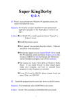
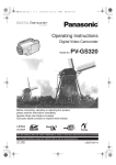
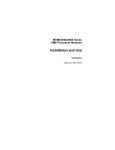
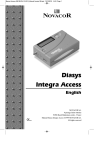
1
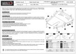
TIL09 FLARES – USER’S MANUAL
This user’s manual refers to the TIL09 torches equipped with flame arrestor type Security :
EQF0625.
This manual does not cover all the safety measures that should be cry out for PLEASE RESPECT ALL THE RULES AND SECURITY INFORMATIONS IN EFFECT DURING
A BURNING OPERATION.
installation, use, and maintenance of equipments for LPG.
Warning: Please inspect the torch regularly and replace any defective part.
PLEASE NEVER USE THE TORCH UP IN CONFIGURATION FOR VAPOR
BURNING IF YOU WANT TO BURN LIQUID LPG.
Generalities :
TIL09 flares are designed to burn vapor and liquid phases of LPG bulk tanks.
TIL09 flares up in configuration for vapor burning are complying with the
recommendation N° MAGV/RP02 issued by the French comity for Butane and propane
(CFBP)
These flares could be equipped with an optional liquid firing head allowing complete
burning of liquid LPG (part N° TIL07TL).
The flare up in configuration for vapor burning is equipped with :
-
1x flame arrestor with 2 security levels (part N°TIL07AF2): It prevents
flashbacks to the tank.
1x flare with vapor firing head and complete flame hider.
1x ignition and permanent standby torch coupled to a standard 13kg cylinder
with a flexible hose: Allows remote ignition of the flare.
1x anti-blowing system mounted on the firing head: Prevents blowing of the
flame.
1x stainless steel flexible hose (overall lenght 20m): For permanent standby
torch feeding.
SYSTEMATICALLY ISOLATE THE REST OF THE INSTALLATION BEFORE ANY
INTERVENTION.
WARNING: NEVER WORK ON THE FLARE DURING BURNING OPERATION.
PLEASE WAIT FOR COMPLETE COOLING OF THE FLARE BEFAORE ANY
INTERVENTION.
NON REPECT OF THIS ADVERTISEMENT MAY CAUSE INJURY.
Routine maintenance :
- If the flare shall not be used for a long time. Please close the holes of the flame
arrestor.
- Check the state of cleanliness of the vapor firing head. (Any dirties could obstruct
the mesh of the anti-blowing system. If needed, please use an explosion proof brush to
clean the mesh.
- The safety devices should be tested once a year.
- Only the manufacturer is able to do this tests.
- Any repair should be done only by the manufacturer.
- Please follow user’s manual instructions of the flame arrestor.
When the user or his representative, decide on his own responsibility to proceed
to the repair or to the modification, this may cause cancellation of the warranty
and any liability of Equip’Fluides is excluded.
Technical caracteristics : working pressure= 3.5 bars (Flame arrestor)
Working temp.= -20/+60°C
S.A au capital de 481.080€
RC Meaux B313497828
Siret b31349782800027-APE 291D
Rue Lavoisier n° 2 - BP N° 509 - 77465 LAGNY S/MARNE
Téléphone : (01) 64.12.46.09 Fax : (01) 64.30.94.17
http://www.equip-fluides.com – e-mail : [email protected]
Page 1/3
Rev.C 04/2010
Assembly:
The TIL09 flare is supplied in kit ready to be mounted.
Please follow instructions on the assembly note.
RECOMMENDATION : Parts of the TIL09 flare are supplied without any treatment.
We recommend to the user to paint all the parts non submitted to the heat.
Installation :
-
Position the flare on a stable place at reasonable distance from any
flammable product.
We recommend to fix the flare on the ground (Use cables and/or screw the
base on the ground).
Respect the rules and security informations in effect.
Mount the 2 horizontal extension tubes.
Mount the flame arrestor on the male ACME coupling at the end of the
enstension.
RESPECT THE DIRECTION OF THE FLOW WRITTEN ON THE FLAME
ARRESTOR (See flame arrestor user’s manual)
DO NOT USE THE FLAMME-ARRESTOR TO BURN LIQUID LPG (voir page
suivante).
Mount liquid firing head.
Connect the feeding flexible hose of the permanent standby torch to a
standard 13 kg cylinder (20x150 threaded coupling).
Connect the other end of the flexible hose to the permanent standby torch.
(Quick coupling)
Connect the main feeding flexible hose to the male acme coupling of the
flame-arrestor.
S.A au capital de 481.080€
RC Meaux B313497828
Siret b31349782800027-APE 291D
Rue Lavoisier n° 2 - BP N° 509 - 77465 LAGNY S/MARNE
Téléphone : (01) 64.12.46.09 Fax : (01) 64.30.94.17
http://www.equip-fluides.com – e-mail : [email protected]
Page 2/3
Rev.C 04/2010
Commissioning :
Open feeding valve on the permanent standby torch.
Position the flame of the long lighter at the bottom of the outlet of the vapor firing
head.
- To start burning, open the feeding valve of the flare (usually mounted on the main
flexible hose, not supplied with the flare)
- Start the burning at a lower flowrate for 5 to 10 minutes, in order not to constrain
the structure by a too rapid rise in temperature.
S.A au capital de 481.080€
RC Meaux B313497828
Siret b31349782800027-APE 291D
Rue Lavoisier n° 2 - BP N° 509 - 77465 LAGNY S/MARNE
Téléphone : (01) 64.12.46.09 Fax : (01) 64.30.94.17
http://www.equip-fluides.com – e-mail : [email protected]
Page 3/3
Rev.C 04/2010
EQF0625BT FLAME ARRESTOR – USER’S MANUAL
This user’s manual refers to the EQF0625BT flame arrestor which equips TIL07 and Check that all sealing surfaces and threads are clean and flawless.
Respect the type of connection: 1’’ NPT or 1’’3/4 ACME if the flame arrestor is supplied with
TIL09 flares or any other LPG pipelines.
This manual does not cover all the safety measures that should be cry out for ACME male and female couplings.
installation, use, and maintenance of equipments for LPG.
When installing a flame arrestor, respect the mounting direction.
An arrow marked on the flame arrestor indicates the flow direction.
Warning: Please inspect the flame arrestor regularly.
Replace any defective flame arrestor. PLEASE NEVER USE THIS FLAME
ARRESTOR WHEN BURNING LIQUID LPG.
Generalities :
The flame arrestor EQF0625BT is designed to prevent any flashback to the tank.
This flame arrestor is equipped with 2 security devices:
-
1x non-return valve: It prevents return of the gaz in the opposite direction of
the normal gas flow.
1x valve melt: which cut off the gas flow in case of flashback.
Technical caracteristics : working pressure= 3.5 bars Working temp.= -20/+60°C
INSTALLATION:
RESPECT INDICATIONS MARQUED ON THE FLAME-ARRESTOR.
Check that the operators are properly trained before any installation or inspection and read
carefully the precautions for use.
EQF0625BT flame arrestors may be installed by well trained operators under the
respect of regulations for LPG equipments and in compliance with the regulations
effective in the country where the flame arrestor will be placed.
S.A au capital de 481.080€
This device may be mounted only on clean and fully functional installations.
After any repair on the pipelines, these must be served and checked.
Install a cut off valve on each ends of the flame arrestor.
It should not be any water or any liquid in the pipeline. On the contrary case the device could be damaged.
Only one pipeline can be connected to the flame arrestor.
PAfter complete installation, check the sealing of each connections.
Routine maintenance :
- If the flare shall not be used for a long time. Please close the holes of the flame
arestor.
- Check the state of cleanliness of the vapor firing head. (Any dirties could obstruct
the mesh of the anti-blowing system. If needed, please use an explosion proof brush to
clean the mesh.
- The safety devices should be tested once a year.
- Only the manufacturer is able to do this tests.
- Any repair should be done only by the manufacturer.
- Please follow user’s manual instructions of the flame arrestor.
When the user or his representative, decide on his own responsibility to proceed
to the repair or to the modification, this may cause cancellation of the warranty
and any liability of Equip’Fluides is excluded.
RC Meaux B313497828
Siret b31349782800027-APE 291D
Rue Lavoisier n° 2 - BP N° 509 - 77465 LAGNY S/MARNE
Téléphone : (01) 64.12.46.09 Fax : (01) 64.30.94.17
http://www.equip-fluides.com – e-mail : [email protected]
Page 1/3
Rev.C 04/2010
Failures : no gas flow.
ROUTINE MAINTENANCE:
If the installation or the flare shall not be used for a long time. Please close the
holes of the flame arrestor.
The safety devices should be tested once a year.
Only the manufacturer is able to do these tests.
The flame arrestor is equipped with a dust filter. Use only Equip’Fluides
original dust filters for EQF0625BT flame arrestors.
When the user or his representative, decide on his own responsibility to
proceed to the repair or to the modification, this may cause cancellation
of the warranty and any liability of Equip’Fluides is excluded.
a) flash back due to defective burner
b) Flashback due to too low flowrate
Check if the devices is suitable with the installation
The device could be obstructed by dirties or liquid going from the pipline. The device should be
repaired by the manufacturer
c) The melt valve has reacted and gas flow is stopped.
It is not possible to see if the melt valve has reacted. The device should be repaired by the
manufacturer.
If a flashback occurred, the flame arrestor and the whole installation should be inspected to
find out the reason of the flashback.
A flame arrestor which has reacted should be changed.
Commissioning :
Open feeding valve on the permanent standby torch.
Position the flame of the long lighter at the bottom of the outlet of the vapor firing
head.
S.A au capital de 481.080€
RC Meaux B313497828
Siret b31349782800027-APE 291D
Rue Lavoisier n° 2 - BP N° 509 - 77465 LAGNY S/MARNE
Téléphone : (01) 64.12.46.09 Fax : (01) 64.30.94.17
http://www.equip-fluides.com – e-mail : [email protected]
Page 2/3
Rev.C 04/2010
- To start burning, open the feeding valve of the flare (usually mounted on the main
flexible hose, not supplied with the flare)
- Start the burning at a lower flowrate for 5 to 10 minutes, in order not to constrain
the structure by a too rapid rise in temperature.
S.A au capital de 481.080€
RC Meaux B313497828
Siret b31349782800027-APE 291D
Rue Lavoisier n° 2 - BP N° 509 - 77465 LAGNY S/MARNE
Téléphone : (01) 64.12.46.09 Fax : (01) 64.30.94.17
http://www.equip-fluides.com – e-mail : [email protected]
Page 3/3
Rev.C 04/2010
1
2
3
4
5
6
7
8
9
10
11
12
A
A
X1
TIL09-10
TIL09-7
X 12
TIL09-5
X1
X3
TIL09-8
X3
TIL09-10
TIL09-5
X9
B
B
X3
TIL09-9
X1
Tête de brûlage
C
X1
TIL09-6
C
Tube vertical 1'' lg 1.5m
MxM1''NPT
X1
RD83F
X1
D
D
Rallonges 1'' lg 6m
MxF1''NPT
X1
RD83
X2
E
E
X72
Vis M10 x 80
F
X15
VIS M10 x 25
X1
TIL07AF2
X4
Cale
F
Flexible inox 1/4'' avec
coupleur STAUBLI
ECROU M10
G
X 72
X1
Objet de la modification
Rev:
Traitement: XXXXXXXXXXXXXX
Matière: XXXXXXXXXXX
Dess: JDP
Date : 09/03/09
A2
H
Echelle : 1 / 10
EQUIP' FLUIDES
2 Rue Lavoisier
77465 LAGNY S/ MARNE
01.64.12.46.08 - 01.64.30.94.17
1
2
3
4
5
6
7
8
Date :
Par:
Rev.
MONTAGE TIL09
CONTENU DU KIT
REF PLAN : MONT TIL09 / KIT
A
G
1
2
3
4
5
6
7
8
9
10
11
12
A
A
M10 x 25
B
B
X9
C
C
X1
Poids: +- 45 kg
D
D
E
E
F
F
G
G
Tolérances générales:+- 0.1 mm
Unitées: mm
Objet de la modification
Rev:
Traitement: XXXXXXXXXXXXXX
Matière: XXXXXXXXXXX
Dess: JDP
Poids: +- 47 kg
1
2
3
4
5
X3
6
Echelle : 1 / 10
EQUIP' FLUIDES
2 Rue Lavoisier
77465 LAGNY S/ MARNE
01.64.12.46.08 - 01.64.30.94.17
7
8
Par:
Rev.
Date : 09/03/09
A2
H
Date :
MONTAGE TIL09
ETAPE 1
REF PLAN : MONT TIL09 / 1
A
1
2
3
4
5
6
7
8
9
10
11
12
A
A
Poids: +- 16 kg
B
B
50
22
X9
X3
C
C
D
D
X9
Poids: +- 7 kg
X1
E
E
F
F
G
G
Tolérances générales:+- 0.1 mm
Unitées: mm
Objet de la modification
Rev:
Traitement: XXXXXXXXXXXXXX
Matière: XXXXXXXXXXX
Dess: JDP
Echelle : 1 / 15
EQUIP' FLUIDES
2 Rue Lavoisier
77465 LAGNY S/ MARNE
01.64.12.46.08 - 01.64.30.94.17
1
2
3
4
5
6
7
8
Par:
Rev.
Date : 09/03/09
A2
H
Date :
MONTAGE TIL09
ETAPE 2
REF PLAN : MONT TIL09 / 2
A
1
2
3
4
6
5
7
8
9
10
11
12
A
A
X3
Poids: +- 15 .5 kg
B
B
M10x80
C
C
X3
X3
D
D
M10x25
E
E
X6
F
F
G
G
Tolérances générales:+- 0.1 mm
Unitées: mm
Objet de la modification
Rev:
Traitement: XXXXXXXXXXXXXX
Matière: XXXXXXXXXXX
Dess: JDP
Echelle : 1 / 10
EQUIP' FLUIDES
2 Rue Lavoisier
77465 LAGNY S/ MARNE
01.64.12.46.08 - 01.64.30.94.17
1
2
3
4
5
6
7
8
Par:
Rev.
Date : 09/03/09
A2
H
Date :
MONTAGE TIL09
ETAPE 3
REF PLAN : MONT TIL09 / 3
A
1
2
3
4
5
7
6
8
9
10
11
12
A
A
Poids: +- 12 kg
X1
17
50
B
B
X9
C
C
M10x80
D
D
X 12
E
E
X 12
F
F
G
G
Tolérances générales:+- 0.1 mm
Unitées: mm
Objet de la modification
Rev:
Traitement: XXXXXXXXXXXXXX
Matière: XXXXXXXXXXX
Dess: JDP
Echelle : 1 / 21
EQUIP' FLUIDES
2 Rue Lavoisier
77465 LAGNY S/ MARNE
01.64.12.46.08 - 01.64.30.94.17
1
2
3
4
5
6
7
8
Par:
Rev.
Date : 15/07/09
A2
H
Date :
MONTAGE TIL09
ETAPE 4
REF PLAN : MONT TIL09 / 4
A
1
2
3
4
5
6
7
8
9
10
11
12
A
A
B
B
X1
C
C
1"3/4 ACME
D
D
X1
E
E
F
F
X1
G
G
Tolérances générales:+- 0.1 mm
Unitées: mm
Objet de la modification
Rev:
Traitement: XXXXXXXXXXXXXX
Matière: XXXXXXXXXXX
Dess: JDP
Echelle : 1 / 21
EQUIP' FLUIDES
2 Rue Lavoisier
77465 LAGNY S/ MARNE
01.64.12.46.08 - 01.64.30.94.17
1
2
3
4
5
6
7
8
Par:
Rev.
Date : 15/07/09
A2
H
Date :
MONTAGE TIL09
ETAPE 5
REF PLAN : MONT TIL09 / 5
A
1
2
3
4
5
6
7
8
9
10
11
12
A
A
B
B
Poids: +- 21 kg
X 12
C
C
D
D
M10x80
A
E
E
X 18
F
F
DÉTAIL A
ECHELLE 2 : 21
X 18
G
G
Tolérances générales:+- 0.1 mm
Unitées: mm
Objet de la modification
Rev:
Traitement: XXXXXXXXXXXXXX
Matière: XXXXXXXXXXX
Dess: JDP
Echelle : 1 / 21
EQUIP' FLUIDES
2 Rue Lavoisier
77465 LAGNY S/ MARNE
01.64.12.46.08 - 01.64.30.94.17
1
2
3
4
5
6
7
8
Par:
Rev.
Date : 15/07/09
A2
H
Date :
MONTAGE TIL07
ETAPE 6
REF PLAN : MONT TIL09 / 6
A
1
2
3
4
5
6
7
8
9
10
11
12
A
A
B
B
Flex inox 1/4'' lg 20m avec coupleur STAUBLI
C
C
TIL07AF2
D
D
X1
X1
E
E
F
F
X2
Rallonge 1'' M x F1'' NPT long 6m
RD83
X1
G
G
Objet de la modification
Rev:
Traitement: XXXXXXXXXXXXXX
Matière: XXXXXXXXXXX
Dess: JDP
Echelle : 1 / 21
EQUIP' FLUIDES
2 Rue Lavoisier
77465 LAGNY S/ MARNE
01.64.12.46.08 - 01.64.30.94.17
1
2
3
4
5
6
7
8
Par:
Rev.
Date : 15/07/09
A2
H
Date :
MONTAGE TIL07
ETAPE 7
REF PLAN : MONT TIL09 / 7
A