1
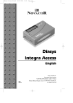
Manuel Access GB REV04-12-2010_Manuel Access GB.qxd 13/12/2010 14:43 Page 1
Diasys
Integra Access
English
NOVACOR SA.
4 passage Saint-Antoine
92508 Rueil-Malmaison cedex - France
Manual Diasys Integra Access ©1999 NOVACOR SA.
All rights reserved
Manuel Access GB REV04-12-2010_Manuel Access GB.qxd 13/12/2010 14:43 Page 2
1. Introduction
4
2. Guarantee
5
2.1.
Specific Guarantees concerning units
5
2.2.
Accessories
5
2.3.
Restrictions of the Guarantee
5
2.4.
Responsibilities
5
2.5.
User Information
6
2.6.
Rights
6
3. How the Diasys Integra Access Functions
7
4. Description of the equipment
8
Diasys Integra Access and Standard Accessories
Optional accessories
8
8
4.1.
The Diasys Integra Access recorder
9
4.2.
4.3.
The battery charger
The cuff and the connecting tube to the Diasys Integra Access
10
11
5. Preparing the Diasys Integra Access for monitoring
12
5.1.
Preparing the battery
5.1.1. The battery charger
5.1.2. The battery
5.1.3. Charging the battery
5.1.4. End of charge
13
13
15
15
16
5.2.
Inserting the battery into the recorder
5.2.1. Insertion
5.2.2 Safeguard battery (non-rechargeable lithium)
17
17
18
5.3.
Programming the Diasys Integra Access
5.3.1. Programming the time
5.3.2. Programming the date
5.3.3. Programming the intervals
18
20
21
22
5.4.
Placing the unit on the patient
5.4.1. Positioning
5.4.2. Recommendations for placing the cuff
5.4.3. Changing arms
5.4.4. Positioning the Diasys Integra Access with the integrated position
sensor (optional)
23
23
25
26
2 • Diasys Integra Access - Manual GB - REV04-12/2010
27
Manuel Access GB REV04-12-2010_Manuel Access GB.qxd 13/12/2010 14:43 Page 3
Summary
28
6.1.
Start up
28
6.2.
Test measurements
28
6.3.
Manually activated measurements
29
6.4.
Palliative measurements
29
6.5.
“Suspend” mode
30
6.6.
Measurements which are not memorised
30
6.7.
Display of measurements
30
6.8.
Stopping measurements
31
6.9.
Display codes
32
7. Reading the recordings
33
7.1.
Transfer to a PC or a printer
33
7.2.
Modem Data Transmission (optional)
34
8. Maintenance
36
8.1.
Handling the equipment
36
8.2.
Cleaning the equipment
36
8.3.
Maintenance
36
8.4.
Calibration test
37
8.5.
Replacing the safeguard battery
38
8.6.
Storing and dispatching
38
8.7.
Preventative maintenance
39
8.8.
Norms and safety standards
39
8.9.
Precautions of use
43
8.10. Physical specifications
43
8.11. Technical specifications
44
8.12. Accessories
44
Diasys Integra Access - Manual GB - REV04-12/2010 • 3
English
6. How the unit functions
Manuel Access GB REV04-12-2010_Manuel Access GB.qxd 13/12/2010 14:43 Page 4
1. Introduction
The Diasys Integra Access is a non-invasive
ambulatory system for measuring and recording blood
pressure in oscillometric mode. It measures the
systole, the diastole, mean blood pressure and the heart
rate for up to 48 hours.
The Diasys Integra Access unit weighs about 200g and
contains the electronic system and pneumatic inflation
module. It is linked to the patient’s cuff with a tubing
system.
The measurements made by the Diasys Integra Access
can be printed out directly in report form by a printer
connected to the unit.
If a computer is used, recording conditions and criteria
can be fixed, and the results of the procedure can be
selected, organised, stored and printed out in a fully
customised report.
4 • Diasys Integra Access - Manual GB - REV04-12/2010
Manuel Access GB REV04-12-2010_Manuel Access GB.qxd 13/12/2010 14:43 Page 5
2. Guarantee
2. Guarantee
NOVACOR undertakes to deliver merchandise conforming
to the technical specifications mentioned and to replace any
merchandise recognised as being defective.
Specific guarantees concerning units
Each unit is identifiable by a specific serial number.
NOVACOR guarantees the unit (Diasys Integra Access and
charger) for one year from the date of delivery against any
defect resulting in abnormal functioning of the unit.
2.2.
Accessories
Equipment which is not an integral part of the unit, in
particular the accessories and cables, are not covered by the
guarantee. Cables with serial numbers are guaranteed for
three months.
2.3.
Restrictions of the guarantee
The guarantee does not apply to:
1. units repaired or opened outside our workshop.
2. units damaged by negligence, by accident or if the user
instructions have not been followed correctly.
If necessary contact your distributor or our after sales
service. We do not accept units returned without prior
agreement.
2.4.
Responsibilities
NOVACOR will not, under any circumstances, be held
responsible for physical or material damage of whatever
nature, arising either directly or indirectly from improper
use of the unit or from failure to follow the instructions in
the user manual.
Although NOVACOR manufactures products to the highest
standards, it cannot be held responsible for the validity or
the accuracy of the measurements made by its units.
Diasys Integra Access - Manual GB - REV04-12/2010 • 5
English
2.1.
Manuel Access GB REV04-12-2010_Manuel Access GB.qxd 13/12/2010 14:43 Page 6
2.5.
User information
All customers duly registered with NOVACOR, or where
applicable, with one of its distributors, will be kept
informed, to the best of NOVACOR’s ability, of any
upgrades and developments to the Diasys Integra Access as
they become available.
2.6.
Copyrights
Diasys Integra Access Manual © 1999 Novacor S.A.All rights reserved.
Diasys Integra Access, DiasySoft, and their respective
logos, are registered trademarks of NOVACOR S.A.
Macintosh is a registered trademark of Apple Computer
International.
MS-DOS and Windows are registered trademarks of
Microsoft Corporation.
6 • Diasys Integra Access - Manual GB - REV04-12/2010
Manuel Access GB REV04-12-2010_Manuel Access GB.qxd 13/12/2010 14:43 Page 7
3. How the Diasys Integra Access functions
The Diasys Integra Access is a non-invasive automatic
ambulatory blood pressure recorder operating in
oscillometric mode.
The oscillometric measurement is based on analysis of
the shape of the oscillometric curve of the cuff
pressure, of which the maximum point represents the
mean pressure.
The patient’s arm must stay still during measurement.
The Diasys Integra Access also has an optional
integrated position sensor enabling the unit to detect
whether the patient is vertical (awake) or horizontal
(resting).
Diasys Integra Access - Manual GB - REV04-12/2010 • 7
English
3. How the Diasys Integra
Access functions
Manuel Access GB REV04-12-2010_Manuel Access GB.qxd 13/12/2010 14:43 Page 8
4. Description
of the equipment
Diasys Integra Access and standard accessories
• Diasys Integra Access recorder,
• Two rechargeable NiMH batteries
(same as Diasys Integra batteries),
• Standard adult sized cuff,
• Protective pouch and belt.
Optional accessories
• Battery charger,
• DiasySoft software, customised according to the
programming options required and the user’s language
and access key,
• Printer,
• Diasys-Printer or Diasys-Computer linking cabl,e
• Diasys-Modem linking cable.
8 • Diasys Integra Access - Manual GB - REV04-12/2010
Manuel Access GB REV04-12-2010_Manuel Access GB.qxd 13/12/2010 14:43 Page 9
4. Description of the equipment
M
P
Mode selector
M = measurement / P= program
P mode: display switched on (On)
and validation of options (Valid)
M mode: monitoring started (On)
and activation of a manual recording (Rec)
Air connector
Rec
On/Valid
Stop
Select
RS232 connector for printer or modem
P mode: next choice (Select)
M mode: stop measurements (Stop)
Battery cover
Diasys Integra Access - Manual GB - REV04-12/2010 • 9
English
4.1. The Diasys Integra Access recorder
Manuel Access GB REV04-12-2010_Manuel Access GB.qxd 13/12/2010 14:43 Page 10
4.2. The battery charger
The Diasys Integra Access functions exclusively with a
high capacity rechargeable battery (NiMH), making it
economical and environmentally friendly.
Batteries are recharged with a fast battery charger specially
designed for the Diasys to ensure optimum performance
and long-life.
The charger is connected to the mains outlet via a
transformer and has two lights on the front panel.
10 • Diasys Integra Access - Manual GB - REV04-12/2010
Manuel Access GB REV04-12-2010_Manuel Access GB.qxd 13/12/2010 14:43 Page 11
4. Description of the equipment
4.3. The cuff and the connection tube
to the Diasys Integra Access
The Diasys Integra Access cuff offers features specially
designed for ambulatory recording:
• Stabilising flap for optimal positioning, to be used with
adhesive pads
• Easy handling
• Washable material
Diasys Integra Access - Manual GB - REV04-12/2010 • 11
English
• Cone-shaped for better ergonomics
Manuel Access GB REV04-12-2010_Manuel Access GB.qxd 13/12/2010 14:43 Page 12
5. Preparing the Diasys
Integra Access for
monitoring
To prepare the unit, follow the instructions below.
• Charge the battery
• Insert the battery
• Program the unit
• Place the unit on the patient
• Start up the unit and carry out the test measurements
12 • Diasys Integra Access - Manual GB - REV04-12/2010
Manuel Access GB REV04-12-2010_Manuel Access GB.qxd 13/12/2010 14:43 Page 13
5. Preparing for monitoring
5.1. Preparing the battery
5.1.1. The battery charger
Red light
low brightness : power
normal brightness blinking: discharging
normal brightness fixed: charging
Green light: end of charge
The front panel
There is an indicator light (LED) on each side of the slot
into which the battery is placed.
The RED light indicates:
• That the charger is working correctly when it is plugged
into the mains outlet: fixed light - low brightness
• That the battery is being discharged, when discharge prior
to charge has been programmed (see chapter 5.1.3):
blinking light- normal brightness
• That the battery is being charged: fixed light - normal
brightness
Diasys Integra Access - Manual GB - REV04-12/2010 • 13
English
The Diasys charger is fast, fully automatic and easy to use.
Manuel Access GB REV04-12-2010_Manuel Access GB.qxd 13/12/2010 14:43 Page 14
The green light indicates that the operation is finished and
the battery is charged.
The back panel (base)
A selector (2 red switches) determines the charge mode to
ensure a long life of the batteries, it is advisable not to
change the position of these switches.
ON
ON
1 2
1 2
It is, however, possible to implement an immediate charge
by changing the position of switch 1:
SWITCH 1 /ON
discharges the battery before
recharging it (factory setting)
SWITCH 1 /OFF
immediate charge
• Whichever mode is chosen, the green light comes on
when the battery is charged indicating that it is ready
to be used.
• The position of switch 2 should never be changed and
should always remain in the position shown above.
• Never use the charger with any batteries other than
those supplied by NOVACOR.
• External power sources must comply with EN 60-601
standards.
14 • Diasys Integra Access - Manual GB - REV04-12/2010
Manuel Access GB REV04-12-2010_Manuel Access GB.qxd 13/12/2010 14:43 Page 15
5. Preparing for monitoring
5.1.2. The battery
Precautions to be taken with the batteries:
• Take care not to invert the polarities.
• Do not store at over 45°C.
• Do not exceed the recommended recharge time,
otherwise the unit risks stopping during a recording.
5.1.3. Charging the Battery
2
1
R
m S
a p
b nu ec
ia
y
P fa lly
an ct
as ur
o ed
n
ic
.
ef
.D
N
10
-1
E H
IE L A
R B
E A m
T E 50
T
A G 5
B AR V H
C ,6
E 3
R HiM
00
0
• Plug the charger into a compatible mains outlet (check
carefully that the voltage marked on the charger
transformer corresponds to the voltage of your mains
supply): the red light will come on immediately with low
brightness.
• Place the battery in the charger, taking care to match
the + and - signs with those on the charger.
• Insert the battery into its slot.
Diasys Integra Access - Manual GB - REV04-12/2010 • 15
English
The Diasys Integra Access is delivered with two
rechargeable Nickel-Metal Hydride (NiMH) batteries.
These batteries have been specially developed for the
Diasys series and can be recharged about 300 times if used
according to the recommendations in this manual.
Manuel Access GB REV04-12-2010_Manuel Access GB.qxd 13/12/2010 14:43 Page 16
• When the battery is placed in the charger the red light
will become brighter and will be either:
- fixed (immediate charge),
- flashing (discharge before recharge).
• Duration of charge cycle:
- Without prior discharge: about a maximum of
1 hour.
- With prior discharge: discharge (up to 1½ hrs)
plus charge (about 1 hr).
• Do not use a different non-Novacor charger to
recharge Diasys Integra Access batteries.
• Go through the charge cycle:
- Systematically when new batteries are used for
the first time.
- At least once a year if the batteries are not in
regular use.
- If the battery has been stored out of the charger
for more than 2 weeks since last being charged
5.1.4. End of charge
When the green light is on the battery is ready to be used
and can be removed for storage or left in the charger up to
one week until required.
Caution: if a charged battery is removed from the charger
and not used for more than two weeks, we recommend that
it be recharged.
• Do not leave a battery in the charger if it is not
plugged into the mains, it will quickly lose its charge!
• Do not leave the charger plugged into the mains
for a long period of time.
• Do not leave a charged battery in a charger plugged
into the mains for a long period of time.
• Do not start a recording using a battery only partcharged, the unit may stop during a measurement.
16 • Diasys Integra Access - Manual GB - REV04-12/2010
Manuel Access GB REV04-12-2010_Manuel Access GB.qxd 13/12/2010 14:43 Page 17
5. Preparing for monitoring
5.2. Inserting the batteries into the recorder
5.2.1. Insertion
• Slide off the battery cover.
• The arrow on the battery should be pointing towards the
bottom of the compartment (as shown below). If it is
difficult to insert the battery do not force it. Check that
the above instructions have been carefully followed
before trying again.
• Holding the battery in place, slot the battery cover back
into the grooves and slide it into place.
• The battery must be replaced before each new clinical
procedure.
0
100
10f. D
Re
R BA
NiMECH TTE
H - ARGRIE
3,6 EA
V - BL
55 E
0m
AH
• Do not store the Diasys with a discharged battery
inside. Do not leave a recharged battery in the Diasys
for more than 2 weeks without using it.
y d .
ll re ic
ia u n
c t o
e cs
p fa a
S u n
n a
a P
my
b
Diasys Integra Access - Manual GB - REV04-12/2010 • 17
English
Slide off the battery cover, if there is already a battery in
the unit, remove it. Insert a recharged battery into the unit
taking care not to invert the polarities.
Manuel Access GB REV04-12-2010_Manuel Access GB.qxd 13/12/2010 14:43 Page 18
5.2.2. Safeguard battery (non-rechargeable lithium)
The Diasys Integra Access has a safeguard battery enabling
program settings and data in memory to be protected if the
main battery fails or is missing, thus providing the user with
maximum security.
The safeguard battery will normally last for 3 to 5 years.
It is not accessible to the user. Its status is systematically
tested every time an NiMH battery is placed in the unit, as
follows:
When the battery is inserted, the Diasys Integra Access
automatically tests the safeguard battery and displays one
of the following messages for 3 seconds
either
indicating that the lithium battery is functioning properly,
or
indicating that the lithium battery is not functioning (see
chapter 8 “replacing the safeguard battery”).
5.3. Programming the Diasys integra Access
M
P
(mode selector in Programming position)
This manual only concerns manual programming. Software
programming is fully explained in the DiasySoft manual.
We recommend that a recharged battery be inserted each
time before programming. If the battery is run down, the
Diasys Integra Access will display the message (ER 14), if
it is dead, the unit’s keys will be blocked (safeguard mode).
18 • Diasys Integra Access - Manual GB - REV04-12/2010
Manuel Access GB REV04-12-2010_Manuel Access GB.qxd 13/12/2010 14:43 Page 19
During programming, if the selector or the two
programming keys are not used for a certain time, the
screen will switch off to save battery power. Press one
of the keys to retrieve the time screen.
Diasys Integra Access - Manual GB - REV04-12/2010 • 19
English
5. Preparing for monitoring
Manuel Access GB REV04-12-2010_Manuel Access GB.qxd 13/12/2010 14:43 Page 20
5.3.1. Programming the time
Press Valid to display the time.
Press Select and the first digit will
flash.
Stop
Rec
Select
On/Valid
Stop
Rec
Select
Press Select to obtain the correct digit.
Stop
Select
Press Valid to confirm. The second
digit will flash.
Adjust the second digit and press valid
to confirm.
The AM/PM setting will flash. Press
Valid to make AM flash. If PM is
required, press Select, then Valid.
When the last digit has been validated,
all four digits will flash. Press Valid to
confirm the time. The date will be
displayed.
Rec
On/Valid
Stop
Rec
Select
On/Valid
Stop
Rec
Select
On/Valid
Stop
Rec
Select
Adjust the two minute digits as above.
On/Valid
On/Valid
Stop
Rec
Select
On/Valid
Stop
Rec
Select
On/Valid
Note that the AM/PM setting is only proposed if the time is
programmed before midday.
20 • Diasys Integra Access - Manual GB - REV04-12/2010
Manuel Access GB REV04-12-2010_Manuel Access GB.qxd 13/12/2010 14:43 Page 21
5. Preparing for monitoring
Press Select to choose the date format
(dd-mm or mm-dd).
Press Valid to confirm. The first digit
will flash.
Stop
Rec
Select
On/Valid
Stop
Rec
Select
On/Valid
Press Select to obtain the correct digit.
Stop
Press Valid to confirm. The second
digit will flash.
Adjust the other digits as above. Press
Valid to confirm.
When the last digit has been
confirmed, all four digits will flash.
Press Valid to confirm the date. The
year will be diplayed.
Press Select to adjust the last digit of
the year and press valid to confirm.
Press Valid again and the interval
programming will appear, or press
Select (year 2000 onwards).
For the year 2000 onwards, adjust the
digits one by one as above, and press
Valid to confirm. The interval
programming will appear.
Rec
Select
On/Valid
Stop
Rec
Select
On/Valid
Stop
Rec
Select
On/Valid
Stop
Rec
Select
On/Valid
Stop
Rec
Select
On/Valid
Stop
Rec
Select
On/Valid
Stop
Rec
Select
On/Valid
Invalid date
If a year is incompatible with the month and date previously
selected, the year and the date will flash alternately.
Press:
• valid to reprogram the date and the year, or press
• select to reprogram just the year.
Diasys Integra Access - Manual GB - REV04-12/2010 • 21
English
5.3.2. Programming the date
Manuel Access GB REV04-12-2010_Manuel Access GB.qxd 13/12/2010 14:43 Page 22
5.3.3. Programming the intervals
The daytime (sun) and night-time
(moon) images are displayed
alternately next to the corresponding
intervals.
Press Select and the daytime interval
will flash.
Press Select to adjust the daytime
interval.
Press Valid to confirm the daytime
interval. The night-time interval will
flash.
Press Select to adjust the night-time
interval.
Press Valid and the new intervals will
flash alternately. Press Valid to end
the programming. The time screen will
be displayed.
Stop
Rec
Select
On/Valid
Rec
Stop
Select
On/Valid
Stop
Rec
Select
On/Valid
Stop
Rec
Select
On/Valid
Stop
Rec
Select
On/Valid
Stop
Rec
Select
On/Valid
The following intervals are available:
Intervals in minutes
Daytime 2 - 3 - 4 - 5 - 6 - 10 - 15 - 20 - 30 - 45 - 60
Night-time 10 - 15 - 20 - 30 - 45 - 60
When the selector is in the Programming mode, press
the pink key to scan the unit’s program: Time, Date,
Year, measurement Intervals.
22 • Diasys Integra Access - Manual GB - REV04-12/2010
Manuel Access GB REV04-12-2010_Manuel Access GB.qxd 13/12/2010 14:43 Page 23
5. Preparing for monitoring
Placing the cuff on the patient
5.4.1. Positioning
English
5.4
Fig 1 - patient with Diasys and cuff.
No particular precautions are necessary for positioning the
cuff for the oscillometric mode, however, we recommend
you follow these indications:
• Locate the path of the humeral artery (ideally with a
stethoscope) about 2cm above the crease of the elbow
• Clean the inside of the arm and apply an antiperspirant if
necessary
• We recommend you place a single-use cuff protector on
the inside of the cuff for hygiene reasons:
- Take the protections off the adhesive strips.
- Apply the adhesive strips on the inside of the
cuff, lining the cuff connector up to the edge of
the pouch (fig 2).
Diasys Integra Access - Manual GB - REV04-12/2010 • 23
Manuel Access GB REV04-12-2010_Manuel Access GB.qxd 13/12/2010 14:43 Page 24
Fig 2 - Positioning the cuff protector
• Position the markings on the cuff (arrow and “ART”)
opposite the artery and wind the cuff evenly around the
arm (fig 3).
Fig 3 - Positioning the cuff
• Pass the tubing behind the patient’s neck and connect the
cuff connector to the Diasys, preferably already in the
protective pouch (fig 4).
Stop
Select
I N T E G
R A
Fig 4 - Connection of the cuff to the Diasys
Diasys is shown without pouch for better illustration.
24 • Diasys Integra Access - Manual GB - REV04-12/2010
Manuel Access GB REV04-12-2010_Manuel Access GB.qxd 13/12/2010 14:43 Page 25
5. Preparing for monitoring
English
• Once the test measurements have confirmed that the
Diasys is working properly, click an adhesive patch onto
the stabilising flap behind the air tubing and place it on
the patient's arm to ensure that the cuff stays in place
during the whole of the monitoring (fig 5).
Fig 5 - Clicking an adhesive patch onto the stabilising
flap and placing it on the patient's arm.
5.4.2. Recommendations for positioning the cuff
- Cuff size
It is essential to choose the appropriate size of cuff for the
circumference of the patient's arm, to avoid any discomfort
or measurement errors.
The maximum arm circumference for the cuff is given by
lining up the two vertical lines where “MAXI” is printed.
Above this limit, a larger cuff should be used.
Correct
Maximum
Cuff too small
Fig 6 - Position of the cuff
Diasys Integra Access - Manual GB - REV04-12/2010 • 25
Manuel Access GB REV04-12-2010_Manuel Access GB.qxd 13/12/2010 14:43 Page 26
Arm circumference
Cuff
18 - 24 cm
Paediatric
24 - 32 cm
Adult
32 - 40 cm
Large
Table: recommended cuff size for arm circumference
- Cuff shape
The Diasys Integra Access cuff is conical, and thus
perfectly adapted to the anatomy of the arm. However, to
avoid any risk of discomfort for the patient, positioning still
requires particular attention:
The two areas of velcro must be lined up and opposing.
The cuff must be wound evenly.
The cuff should be neither too loose (this could
increase the inflation time and result in a malfunction,
in which case the relevant error code would be
displayed) nor too tightly wound around the patient’s
arm (uncomfortable).
5.4.3. Changing arm
The cuff has been designed so that it can, if necessary, be
worn on the right arm.
This is done as follows:
- Disconnect the air tubing from the Diasys.
- Open the cuff cover and remove the bladder, passing the
tube under the stabilising flap.
- Turn the bladder over.
- Put the bladder back in the cuff making sure it is flat,
with the tube coming out opposite the stabilising flap.
Close the cuff.
26 • Diasys Integra Access - Manual GB - REV04-12/2010
Manuel Access GB REV04-12-2010_Manuel Access GB.qxd 13/12/2010 14:43 Page 27
5. Preparing for monitoring
1
English
2
3
Fig 7 - Changing the bladder over
- Do not forget to reposition the tube under the stabilising
flap when going back to using the “left arm”.
5.4.4. Positioning the Diasys Integra Access with integrated
position sensor (optional)
“Standing” position (patient sitting or standing up): the unit
must be vertical, it should be positioned as normal on the
belt. (fig 1).
“Lying” position (patient laying down): the unit must be
horizontal. The patient can therefore keep it attached to the
belt if lying down. He can also take the belt off, but must
keep the unit down flat (fig 8).
Fig 8 - Recommended Diasys position when patient lying down
Diasys Integra Access - Manual GB - REV04-12/2010 • 27
Manuel Access GB REV04-12-2010_Manuel Access GB.qxd 13/12/2010 14:43 Page 28
6. How the unit functions
6.1. Start up
M
P
(Mode selector in measurement position)
Before putting the Diasys in its pouch, check that the mode
selector is in the MEASUREMENT position and that the
unit is not connected to a terminal (indicated by “COMM”
or “MOD” on the display).
To start up the unit, keep the pink key pressed down and
release it after the fourth beep.
One of the following messages will be displayed for 10
seconds:
Battery replaced since previous start up.
Battery not replaced since previous start up (battery should
be charged).
Press the pink key briefly during this 10 second display and
monitoring will be initiated in the oscillometric mode.
6.2. Test measurements
M
P
(Mode selector in measurement position)
At the start of the monitoring, the Diasys Integra Access
automatically carries out two test measurements in
oscillometric mode separated by a two minute interval
(with a minimum of 30 seconds between the end of the first
and the beginning of the second).
These measurements allow the Diasys to adapt the
monitoring parameters.
28 • Diasys Integra Access - Manual GB - REV04-12/2010
Manuel Access GB REV04-12-2010_Manuel Access GB.qxd 13/12/2010 14:43 Page 29
6. How the units functions
At the start of the monitoring the inflation level is
220mmHg, the following levels being situated at about
40mmHg above the previous systole.
This will reduce the measurement time, for extra
comfort. It will also reduce the risk of errors due to
artefacts.
• The two test measurements are never included in the
statistical analysis. They are, however, printed on the
report and identified as being test measurements.
• If there is no specific programming, the standard
deflation steps.
6.3. Manually activated measurements
The pink key (On) enables manual measurements to be
triggered whenever required. Measurements activated
manually are carried out in the unit’s operating mode.
The next pre-programmed measurement will be cancelled if
it is due to occur in less than two minutes.
6.4. Palliative measurements
If a measurement is defective, a palliative measurement will
be triggered two minutes after the beginning of this
defective measurement and at least 30 seconds after the end.
A palliative measurement will not, however, be made if the
interval between two pre-programmed measurements is less
than five minutes.
Manual and palliative measurements do not disrupt the
sequence of the pre-programmed measurement intervals.
Diasys Integra Access - Manual GB - REV04-12/2010 • 29
English
• It is important to tell the patient that his cuff arm must
remain still during measurement.
Manuel Access GB REV04-12-2010_Manuel Access GB.qxd 13/12/2010 14:43 Page 30
6.5. “Suspend” mode
If the measurement and the corresponding palliative
measurement fail four times consecutively the Diasys
Integra Access goes into “suspend mode”.
The measurements will be carried out according to the
programmed cycle, but without the palliative
measurements. Also, the inflation level will be 150mmHg.
As soon as a valid measurement is recorded, the unit comes
out of “suspend” mode and the recording continues as
initially programmed.
6.6. Measurements which are not memorised
By pressing the two keys simultaneously, the physician can
trigger, at any time, a measurement which will not be
memorised (measurements are displayed only) without
affecting the ongoing program.
Press Valid and Select simultaneously
to trigger a measurement which will
not be memorised.
Stop
Rec
Select
On/Valid
6.7. Display of measurements
After each measurement the unit displays successively:
Standard function:
Measurement mode
Systolic pressure
Diastolyc pressure
Heart rate
30 • Diasys Integra Access - Manual GB - REV04-12/2010
Manuel Access GB REV04-12-2010_Manuel Access GB.qxd 13/12/2010 14:43 Page 31
6. How the units functions
Options:
(Diasys Integra Access with position sensor option)
Patient's position
6.8. Stopping measurements
For safety and comfort reasons, it is possible to interrupt a
measurement or the monitoring as follows:
To stop an ongoing measurement,
press the green key briefly. Error 17
will be displayed (see the display table
overleaf).
Monitoring can be stopped at any time,
by holding the green key down (you
will hear a series of beeps). STOP will
be displayed.
Stop
Rec
Select
On/Valid
Stop
Rec
Select
On/Valid
No more measurements can be made until the pink key has
been pressed.
Pressing the pink key will trigger two test measurements
and the recording will continue normally.
Diasys Integra Access - Manual GB - REV04-12/2010 • 31
English
or
Manuel Access GB REV04-12-2010_Manuel Access GB.qxd 13/12/2010 14:43 Page 32
6.9. Display codes
As well as the display of the functioning mode, any
problems occuring during a measurement are indicated by
the display of an error code (see below) which is also noted
as such on the printed report if the software is not used.
If the DiasySoft software is used, these problems will be
detailed both on the computer screen and on the report.
Display
Meaning
Comment
OSCI
Oscillometric mode
COMM
Communication established with printer or computer
MOD
Communication established with modem
GOOD Modem transmission successful
TEST
Calibration test
STOP
Manual stopping of monitoring
Stop key held down
Er 01
Defective solenoid valve
Transitory electrical problem. If problem
continues, contact your distributor.
Er 02
Auto Calibration impossible
Residual pressure in cuff. Check air tubing.
If problem continues, contact your
distributor.
Er 03
Abnormal inflation
Tubing disconnected, bent, pierced or
blocked or cuff too loose. Check the air
tubing and connector and that the cuff is
properly wound around patient’s arm.
Er 04
Measurement not validated
Diastole ≤ 50mm not confirmed
Er 05
Abnormal pressure variation
Muscular contraction or excessive exercise.
Er 07
Excessive measurement time
Measurement time >120 s.
Er 09
Excessive cuff pressure
Er 10
Excessive noise or artefacts
impossible
Er 11
Systolic pressure ≤ 50mmHg
Er 12
Diastolic pressure ≤ 30mmHg
Er 14
Battery run down
Er 15
Not used
Er 16
Stopped by connection
connected to Diasys.
Recording stopped because cable link
Er 17
Measurement stopped manually
Stop key pressed during measurement
Er 18
Stopped by switching mode selector Mode selector switched from
measurement position to
programming position
Er 19
Impossible to process oscillometric shapes
Er 25
Heart rate unstable during measurement
Er 26
Error during modem transmission (cf. chapter 7.2)
Er 27
Connection to number called impossible during transmission (cf. chapter 7.2)
32 • Diasys Integra Access - Manual GB - REV04-12/2010
Interference on signal; measurement
Manuel Access GB REV04-12-2010_Manuel Access GB.qxd 13/12/2010 14:43 Page 33
7. Reading the recordings
7. Reading the recordings
Connect the Diasys to a printer or a computer equipped
with DiasySoft software with the cable link.
This connection will automatically interrupt the ongoing
recording and the unit will display COMM
(Communication). This message is displayed during the
whole time that the Diasys is connected.
If COMM is not displayed, this probably means that the
unit is in the safeguard mode, in which case the battery
should be changed. If the problem continues, check that the
cable link is properly connected.
The report is printed as soon as the printer is ready.
If the battery is dead (keys blocked and blank display), or
run down (Er.14), disconnect the cable and change the
battery to resume printing. Wait until “8888” is no longer
displayed before connecting the Diasys.
Note that it is always possible to make a print-out as long as
a new recording has not been initiated.
Also, a recording can be continued after data transmission
to a PC: press the pink key after disconnecting the Diasys.
This is not possible after direct transmission to a printer.
Connecting the Diasys to a printer or a computer
requires different cable links. Ask your distributor for
details.
Diasys Integra Access - Manual GB - REV04-12/2010 • 33
English
7.1. Transmission to a PC or a printer
Manuel Access GB REV04-12-2010_Manuel Access GB.qxd 13/12/2010 14:43 Page 34
7.2. Modem Transmission (optional)
This option allows the automatic transmission of the whole
test in progress to a remote computer, via a modem. To
continue with the recording, restart the unit (cf. chapter 6.1)
This requires:
- an M-series Diasys integra Access (M for “Modem
Transmission”)
- a modem that can call out (must be given to the patient
with the Diasys)
- a Diasys-modem cable
- a Computer with a reception modem
- the number to be called (reception modem) entered in the
DiasySoft communication window (version V4.5 or a
above) during programming.
- the reception computer must be on, and the NovaModem
tele-reception module open and waiting reception
The modem must be plugged into the mains and the
telephone socket and switched on before transmission.
Simply connect the Diasys to the modem using the specific
cable to automatically initiate transmission. “Mod” is
displayed during transmission, replaced by “Good” at the
end of a successful transmission.
If “COMM” is displayed, check that the modem is plugged
in and switched on.
If the messages Er26 or Er27 or “COMM” are displayed:
- disconnect the Diasys from the modem
- turn off and switch back on the modem
- reconnect the Diasys to the modem to trigger a new
transmission
34 • Diasys Integra Access - Manual GB - REV04-12/2010
Manuel Access GB REV04-12-2010_Manuel Access GB.qxd 13/12/2010 14:43 Page 35
7. Reading the recordings
If the problem continues, the caller should check with the
receiver that everything is in order at his end (computer
with modem and NovaModem open awaiting reception).
English
After transmission the monitoring can continue by simply
pressing the pink key.
Diasys Integra Access - Manual GB - REV04-12/2010 • 35
Manuel Access GB REV04-12-2010_Manuel Access GB.qxd 13/12/2010 14:43 Page 36
8. Maintenance
8.1. Handling the equipment
Do not use your nails or a sharp object when pressing the
programming keys.
The design of the Diasys Integra Access (exterior air
connector) is such that it cannot be made waterproof.
The unit should not be exposed to dust or humidity and
great care must be taken to ensure that it is never sprayed
with or immersed in water.
8.2. Cleaning
Clean the Diasys Integra Access regularly with a soft cloth,
lightly moistened with alcohol or a cleaning product not
containing solvents or detergents.
Avoid all contact with liquids.
For hygiene, clean the cuff cover in soapy water after each
patient, by hand or in a washing machine on delicate cycle
(30°-40°).
8.3. Maintenance
Maintenance is carried out in our workshop, as rapidly as
possible. We are unable, however, to provide a loan unit
during the repair period or to provide compensation of any
kind.
Transport costs are the customer’s liability, including units
under guarantee. If the unit is examined outside the
guarantee period there will be a minimum charge for the
administrative and testing costs.
Upon receipt of the unit, after the diagnostic tests, a quote
will be sent by mail or by fax. No intervention can be
carried out without an order from the client.
36 • Diasys Integra Access - Manual GB - REV04-12/2010
Manuel Access GB REV04-12-2010_Manuel Access GB.qxd 13/12/2010 14:43 Page 37
8. Maintenance
8.4. Calibration test
The user can check that the Diasys is properly calibrated.
M
Press the On/Valid to display Time.
Press both keys simultaneously.
The unit displays TEST...
...then Zero after about 5 seconds.
P
Stop
Rec
Select
On/Valid
Rec
Stop
Select
On/Valid
Stop
Rec
Select
On/Valid
• Connect the Diasys, a mercury column and an inflation
bulb together using a Y shaped tube (see below). Check
that the two measurements match.
• Press one of the keys or switch the mode selector to the
Measurement position to end the test phase.
Rec
On/Valid
Stop
Select
Calibration test
Diasys Integra Access - Manual GB - REV04-12/2010 • 37
English
Put the mode selector in the
Programming position.
Manuel Access GB REV04-12-2010_Manuel Access GB.qxd 13/12/2010 14:43 Page 38
When the test is finished, the unit will not function for
ten seconds. Any attempt to use the functions will
result in a beep.
If the fault “Auto calibration impossible” (Er.02) occurs
during the calibration test, restart the operation.
However, if the pressure exceeds the maximum limit
(Excessive cuff pressure - Er. 09) the test will not be
affected.
We recommend carrying out the calibration test at least
once a year, in order to avoid any loss in performance.
8.5. Replacing the safeguard battery
The lithium safeguard battery is indispensable to the correct
functioning of the Diasys Integra Access. When it is
completely run down the message LITH is displayed (see
chapter 5.2.2). It can only be replaced in an authorised
workshop.
Should this message be displayed, contact your distributor,
who will tell you where to send the unit.
8.6. Storage and dispatching
Remove the battery if the Diasys is to be stored for more
than a few days.
The Diasys Integra Access and the battery charger are
delivered in a protective packaging. Check that the unit is
intact before use (bad transport conditions could damage
unit performance). Keep all packaging should the unit need
to be transported at a later date.
38 • Diasys Integra Access - Manual GB - REV04-12/2010
Manuel Access GB REV04-12-2010_Manuel Access GB.qxd 13/12/2010 14:43 Page 39
8. Maintenance
8.7
Preventative maintenance
The check up must be carried out in our workshop, or by an
approved distributor.
The invoicing covers the tests only, the quote for any
necessary repair will be sent by mail or by fax. The repair
can only be carried out upon reception of a customer order.
8.8. Norms and safety standards
Diasys Integra Access work exclusively with an internal power source and comply with
class BF device protection standards.
This sign on a device indicates to the user that complementary information is to be
consulted in the accompanying documents.
CEM
Diasys Integra Access complies to the EN 60 601 1 2 electromagnetic compatibility
standard.
However, use under certain specific conditions may be effected by disturbances.
CE mark conform to the 93/42/CEE European Directive applied to medical devices.
The product should be disposed in an appropriate recovery and recycling structure.
The device does not possess any specific protection against humidity, as a consequence,
it is recommended to store it in a dry place.
Storage Temperature Limits.
Keep away from sunlight.
Humidity Storage Limits.
Pressure Storage Limits.
Diasys Integra Access - Manual GB - REV04-12/2010 • 39
English
A preventative check up of the unit and cuffs is
recommended every two years. This check up will reduce
the number of potential break downs and prolong its useful
life. The unit will be checked for correct functioning, in
particular the pressure measurement circuit.
Manuel Access GB REV04-12-2010_Manuel Access GB.qxd 13/12/2010 14:43 Page 40
The Diasys Integra Access:
• Complies with standards of protection against low
frequency electrical shocks.
• Works exclusively with an internal power source.
• Is not protected against water penetration.
• Is designed to work on an irregular basis.
• Can not be used in the presence of an inflammable
anaesthetic and air mix, oxygen or nitrous oxide.
• Should not be used if the casing is damaged (broken or
cracked) to avoid any electrical contact.
• Complies with the EN 1041 standard in force.
The Diasys Integra Access recorder requires a high
performance power supply. NOVACOR has therefore
developed a special NiMH battery.
Using any other batteries in the Diasys could seriously
damage the unit. NOVACOR recommends the exclusive
use of its own batteries.
The batteries should be disposed of in specific containers.
The destruction of the unit must respect the rules in force
for the elimination of waste.
NOVACOR will provide electrical circuit diagrams for
customers if required.
Warning !
Only devices complying with IEC 950 standards can be
connected.
40 • Diasys Integra Access - Manual GB - REV04-12/2010
Manuel Access GB REV04-12-2010_Manuel Access GB.qxd 13/12/2010 14:43 Page 41
Diasys Integra Access is meant to be used in an electromagnetic environment only as
specified below. The clinician should make sure the device is used in such an
environment.
Electromagnetic transmissions
Transmission trials
Conformity
Warnings regarding the electromagnetic
environment
RF CISPR 11 transmissions
Group 1
DIASYS uses RF energy for internal use only. As a
consequence, RF transmissions are very weak and are
not likely to cause any interference with a nearby
electronic device.
RF CISPR 11 transmissions
B Class
DIASYS can be used in all institutions, including in
domestic buildings.
Harmonics transmission
N/A
CEI 61000-3-2
Tension fluctuation transmission
CEI 61000-3-3
Electromagnetic immunity
Immunity trials
Trial levels
CEI 60601
Conformity
Warning regarding the electromagnetic
environment
Electrostatic
shock
+/- 6kV in contact
+/- 8kV in air
Congruent
It is appropriate that:
That floors be made with wood, concrete or tiles.
If floors are covered with synthetic materials,
relative humidity should be of at least 30%.
Immunity trials
Trial levels
CEI 60601
Conformity
Warning regarding the electromagnetic
environment
Magnetic field at
electric network’s
frequency
(50/60 Hertz)
3 A/m
Congruent
Magnetic field at electric network’s frequency
should be at levels that characterize
a representative place located in a typical
hospital environment.
RF conduct
3 Veff
3V
CEI 61000-4-6
From 150 kHz
to 80 MHz
outside
ISM brackets
Portable and RF mobile communication
devices should not be located too close to any
part of DIASYS, including cables; the
recommended separation distance should be
the respected, computed from the equation
applicable to the transmitter frequency.
CEI 61000-4-8
Recommended separation distance
d = 1,16 √p
d= recommended separation distance in m
p = maximum power of transmitter output in W
Ex: See the following table
Interferences can occur near devices marqued
with the following symbol:
Diasys Integra Access - Manual GB - REV04-12/2010 • 41
Français
8. Annexe
Manuel Access GB REV04-12-2010_Manuel Access GB.qxd 13/12/2010 14:43 Page 42
RF radiated
CEI 61000-4-3
3 V/m of 80MHz
at 2,5GHz
3 V/m
Recommended separation distance
D*= 1,16 √p
from 80MHz to 800 Mhz
d**= 2,3 √p
of 800Mhz at 2,5Ghz
d= Recommended separation distance in m
p = maximum power of transmitter output in W
Field intensity of RF transmitters should be set,
determined by an electromagnetic investigation
on locationa, and should be lower than the level
of conformity, in each frequency rangeb
*Ex : See the following table
Note 1 : At 80MHz and at 800 MHz, the highest frequency range applies.
Note 2: These guides cannot apply in all situations. The electromagnetic spread is affected by the absoption
and by the reflexions of structures, objects and people.
a
a Field intensities of the transmitters that are set, such as base stations for radiotelephones
(cellular/wireless) and land mobile radios, amateur radio, radio broadcasting AM and FM, and TV
broadcasting, cannot be theoretically forecasted with accuracy. In order to evaluate the electromagnetic
environment due to set RF transmitters, an electromagnetic investigation on location must be considered.
If the field intensity, measured at the location where the DIASYS, including the cables, is used, exceeds the
level of RF conformity applicable above, the DIASYS must be observed, including the cables, to check if it is
running normally. If abnormal performances are observed, extra measures may be necessary, in order to
reorient or reposition the DIASYS, including the cablesb, on the range of frequencies 150kHz to 80MHz,
field intensities must be lower than 3 V/m.
Recommended separation distances between portable devices and RF communication mobiles and the
DIASYS.
The DIASYS is meant to be used in an electromagnetic environment in which RF disturbances are checked.
The DIASYS user can help prevent electromagnetic disturbances by maintaining a minimum distance
between the portable device and the RF communication mobile (transmitters) and the DIASYS, as it is
recommended below, according to the maximum transmission power of the communication device.
Maximum
transmission
power assigned
to the transmitter
(W)
Separation distance in accordance with the tranmitter frequency (m)
From 150 kHz to 80 MHz
From 80 MHz to 800 MHz
From 800 MHz to 2,5 GHz
d = (3,5/3) √p
d = (3,5/3) √p
d = (7/3) √p
0,01
0,1
0,1
0,2
0,1
0,3
0,3
0,7
1
1,1
1,1
2,3
10
3,6
3,6
7,3
100
11,6
11,6
23,3
For transmitters for which the maximum transmission power assigne dis not displayed above, the
recommended separation distance d in meters (m) can be estimated bu using the equation applicable to the
frequency of the tranmitter, where P is the maximum power of output of the transmitter in watts (W),
according to the manufacturer of that transmitter.
Note 1 : At 80 MHz and at 800 MHz, The separation distance for the highest frequency range applies.
Note 2 : These guides may not be applied in every situation. The electromagnetic spread is affected by the
absorption and by the reflexion of structures, objects, and people. Ces guides peuvent ne pas s'appliquer dans
toutes les situations.
42 • Diasys Integra Access - Manual GB - REV04-12/2010
Manuel Access GB REV04-12-2010_Manuel Access GB.qxd 13/12/2010 14:43 Page 43
8.9. Precautions of use
• Certain particular physiological characteristics of a
patient (ausculatory gapss, arrhythmia) could influence
the reliability of the measurement. We recommend
checking the unit is working correctly by comparing a
measurement with that of a stethoscope before beginning
the monitoring.
• This equipment must be used by qualified medical
personnel, trained in its use.
• The patient should be informed about possible
malfunctions of the unit (excessive or frequent inflations,
permanent pressure in the cuff) and of the possibility to
stop a measurement or the recording himself at any time.
8.10. Physical specifications
DIASYS
CHARGER
Length
93 mm
88 mm
Width
63 mm
88 mm
Height
27 mm
34 mm
Weight with batteries
195 g
130 g
Storage temperature
-40 C — + 70 C
-40 C — + 70 C
Functioning temperature
+0 C — + 50 C
+0 C — + 50 C
Diasys Integra Access - Manual GB - REV04-12/2010 • 43
Français
8. Annexe
Manuel Access GB REV04-12-2010_Manuel Access GB.qxd 13/12/2010 14:43 Page 44
8.11. Technical specifications
recorder type
pressure holter
measurement mode
oscillometric
recording length
up to 48 hrs
maximum measurements
200
measurement precision
+/- 3 mmHg
deflation levels
8-12 mmHg
Signal input/output type
type RS 232*
measurement ranges
systole
295-50 mmHg
diastole
180-30 mmHg
mean
295-30 mmHg
heart rate
240-40 min
* : Complies to the EIA-232 E standard
8.12. Accessories
Accessory
Reference
Diasys Integra Access
D11-8125
Battery
D10-1000
Charger
D10-8122
Printer
According to model
Diasys-Printer Cable
D10-4000
DiasySoft for PC
D10-7000-PC
DiasySoft for Mac
D10-7000-Mac
Diasys-PC cable
D10-5000-00
Diasys-Mac cable
D10-5000-01
PC access key
D10-7400
Mac access key
RTE-8120-01
Diasys Integra Access Manual
D11-7100
Diasysoft manual
D10-7200
Diasys Integra Access / DiasySoft quick reference guide
D11-7200
Standard adult cuff (bladder included)
D11-3000-00
Standard large adult cuff (bladder included)
D11-3002-00
Adhesive pads for stabilising flap
D10-8073
Diasys Integra Access protective pouch
D11-8126
Adult cuff protectors (50)
D10-3000-06
44 • Diasys Integra Access - Manual GB - REV04-12/2010
-1