1
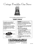
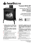
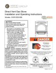
Registration no.
SCAN 1 & 2 DIRECT
VENTED GAS STOVE
INSTRUCTIONS FOR
INSTALLATION AND USE
WARNING:
If the information in these instructions is not followed exactly, fire or explosion may
result causing property damage, personal injury or loss of life
-
Do not store or use gasoline or other flammable vapors and liquids in the vicinity of this or any other
appliance
-
WHAT TO DO IF YOU SMELL GAS:
• Shut off the gas supply.
• Open windows; do not touch any electrical switches.
• Do not try to light any appliance, extinguish any open flame.
• Do not use the phone in your building.
• Immediately call your gas supplier from a neighbor’s phone. Follow the gas supplier's
instructions.
• If you cannot reach your gas supplier, phone the fire department.
-
Installation and service must be performed by a qualified installer, service agency or the gas supplier.
-
The Commonwealth of Massachusetts requires this product be installed by a licensed Plumber or
Gas Fitter.
SAVE THIS MANUAL FOR FUTURE REFERENCE.
This stove may be installed in an aftermarket permanently located manufactured home
(USA only) or mobile home where not prohibited by local codes.
This stove is only for use with the type of gas indicated on the rating plate. This stove is not
convertible for use with other gases unless a certified kit is used.
T este d &
L i st e d b y
B ea v e r to n
O r e gon U SA
O M N I - T e s t L a b o r a t o r ie s , I n c.
September 2005
KROG IVERSEN & CO. A/S 5492 VISSENBJERG DENMARK
1. Introduction:
We welcome you as a new owner of a Scan gas stove. In purchasing a Scan gas stove you have
joined the growing ranks of concerned individuals whose selection of energy systems reflects both
a concern for the environment and aesthetics. The Scan gas stove is one of the finest home stoves
the world over. This manual will explain the installation, operation and maintenance of the Scan
gas stove. Please familiarize yourself with the owner’s manual before operating your gas stove and
save the manual for future reference. Included are helpful hints and suggestions that will make the
operation and maintenance of your new stove an easier and more enjoyable experience. We offer
our continued support and guidance to help you achieve the maximum benefit and enjoyment from
your Scan gas stove.
Important information:
No other Scan stove has the same registration number as yours. The registration number is fixed to
the stove and is located behind the front panel on the right side of the stove. See fig 1.
Mail your warranty card today, and
save your sales receipt.
To receive full warranty coverage,
you will need to show evidence of
the date you purchased your stove.
Do not mail your sales receipt to us.
We suggest that you attach your
Sales receipt to this page so that you
will have all the information you
need in one place should the need
for service or information occur.
We recommend that you fill in the
information below.
Model:
Scan 1 or 2 GAS
Registration no.
Purchase date:
Purchased from:
Service Phone no:
Gas supplier phone no:
2
2. Safety precautions:
ATTENTION CONSUMER:
In order to ensure safe and effective installation, this stove must be installed only by a qualified
agency, individual, firm, corporation, or company that is experienced in the installation, repair and
servicing of this type of stove and is familiar with the building codes and installation techniques
appropriate in your area. Contact your stove dealer or local gas supplier for the name of a qualified
service person.
INSTALLER:
Please read this manual carefully before your begin the installation procedures. Failure to follow
instructions may result in property damage, bodily injury or loss of life. This manual contains important user information. Keep this manual with the stove after installation is complete.
Contact your local building officials to obtain a permit and information on any installation restrictions or inspection requirements in your area.
Notify your insurance company of this stove as well
It is imperative that control compartments, screens, or circulating air passageways of the gas stove
be kept clean and free of obstructions.
These areas provide the air necessary for safe operation.
Do not store or use gasoline or other flammable liquids in the vicinity of this stove.
If the flame becomes sooty dark orange in color or extremely tall, do not operate the stove. Call your
dealer and arrange for proper servicing.
Do not operate the stove if it is not operating properly in any fashion or if you are uncertain. Call
your stove dealer for a full explanation of your stove and what to expect.
Do not use this stove if any part has been under water. Immediately call a qualified service technician
to inspect the stove and to replace any part of the control system and any gas control; which has been
under water.
Do not place clothing or other flammable items on or near the stove. Because a thermostat can control this stove there is a possibility of the heater to turning on and igniting any items placed on or
near it.
The viewing glass should only be open for conducting service or maintenance.
Any safety screen or guard removed for servicing must be replaced prior to operating the stove.
Do not operate with the glass removed or damaged.
Operate the stove according to the instructions included in this manual.
If the main burner does not start correctly, turn the gas off at the gas control valve and call your
stove dealer for service.
This stove is not for use with solid fuel.
3
Do not place anything inside the firebox (except the included
gas logs, baffle plate and fire back
plates).
If the log set became damaged, replace with an original Scan log set.
Children and adults should be alerted to the hazards of high surface temperature and should stay
away to avoid burns or clothing ignition.
Instruct everyone in the house how to shut gas off to the stove and at the gas main shut off valve.
The gas main shut off valve is usually next to the gas meter or propane tank and requires a wrench to
shut off.
Start the stove using the built-in piezo igniter. Do not use matches or any other external device to light
your stove.
Never remove, replace, modify or substitute any part of the stove unless instructions are given in this
manual. All other work must be done by a trained technician. Do not modify or replace orifices
The pilot flame must contact the thermopile and thermocouple (see section 6.3) if it does not, turn on
the gas control valve to OFF and call your stove dealer.
Do not throw this manual away. This manual has important operating and maintenance instructions
that you will need at a later time. Always follow the instructions in this manual.
If the stove is equipped with optional blower; which requires 120 volt power, do not remove the
grounding prong from the plug. Do not route the electrical cord in front of, over, or under the stove.
Krog Iversen & CO grants no warranty, implied or stated, for the installation or maintenance of your
stove, and assumes no responsibility of any consequential damage(s). Please see section 9 Warranty
conditions.
The stove, when installed, must be electrically grounded in accordance with local codes or, in the
absence of local codes, with the National Electrical code, ANSI/NFPA 70, or the Canadian Electrical
Code, CSA C22.1
4
3. Table of Contents:
1. Introduction:................................................................................................................................................................................................2
2. Safety precautions: ......................................................................................................................................................................................3
3. Table of Contents:.......................................................................................................................................................................................4
3. Table of Contents:.......................................................................................................................................................................................5
4. Specifications ..............................................................................................................................................................................................6
4.1 Features:....................................................................................................................................................................................................6
4.2 Installation options:...................................................................................................................................................................................6
4.3 Heating specifications: ..............................................................................................................................................................................6
4.4 Weight:......................................................................................................................................................................................................6
4.5 Dimensions: ..............................................................................................................................................................................................7
4.6 Fuel: ..........................................................................................................................................................................................................7
5. Installation (for qualified installer only):....................................................................................................................................................8
5.1 Installation warnings: ................................................................................................................................................................................8
5.2 Packing list:...............................................................................................................................................................................................8
5.3 Additional items required:.........................................................................................................................................................................8
5.4 Installation overview:................................................................................................................................................................................9
5.5 Installation hints:.......................................................................................................................................................................................9
5.6 High altitude: ............................................................................................................................................................................................9
5.7 Stove clearances:.....................................................................................................................................................................................10
5.8 Mobile home requirements:.....................................................................................................................................................................10
5.9 Stove placement requirements.................................................................................................................................................................10
5.10 Floor protection requirements: ..............................................................................................................................................................11
5.11 Gas line installation:..............................................................................................................................................................................11
5.12 Gas inlet pressure: .................................................................................................................................................................................12
5.13 Vent requirements: ................................................................................................................................................................................13
5.14 Vent restrictor adjustment: ....................................................................................................................................................................14
5.15 Approved venting configurations for vertical terminations with two 90° elbows: ................................................................................15
5.16 Approved venting configurations with a horizontal termination and one 90° elbow:............................................................................16
5.17 Approved venting configurations for vertical terminations:..................................................................................................................17
5.18 Vent termination clearances: .................................................................................................................................................................19
5.19 Finalizing the installation ......................................................................................................................................................................20
5.20 Scan 1 Gas: ..........................................................................................................................................................................................21
5.21 Removal of: face and glass panels: .......................................................................................................................................................22
5.22 Firebrick and baffle plate installation:...................................................................................................................................................23
5.23 Log installation: ....................................................................................................................................................................................24
6. Operation: .................................................................................................................................................................................................25
6.1 Before you begin:....................................................................................................................................................................................25
6.2 For your safety read before lighting: .......................................................................................................................................................26
6.3 Lighting instructions: ..............................................................................................................................................................................27
6.4 Starting the stove for the first time: .........................................................................................................................................................28
6.5 Adjusting the flame height: .....................................................................................................................................................................28
6.6 Adjusting the blower speed (optional): ...................................................................................................................................................29
6.7 Normal operating sounds: .......................................................................................................................................................................29
7. Maintenance: (for qualified service personnel only) ................................................................................................................................29
7. Maintenance: (for qualified service personnel only) ................................................................................................................................30
7.1 Maintaining your stove’s appearance:.....................................................................................................................................................30
7.2 Annual service procedure:.......................................................................................................................................................................30
7.3 Troubleshooting table: ............................................................................................................................................................................31
7.4 How this stove works:.............................................................................................................................................................................32
7.5 Millivolt wiring diagram: ........................................................................................................................................................................33
7.6 Replacement part list:..............................................................................................................................................................................33
8. Optional equipment (for qualified installer only):....................................................................................................................................34
8.1 Conversion from NG to LP (for qualified installer only): ......................................................................................................................34
8.2 Conversion from LP to NG (for qualified installer only): .......................................................................................................................34
8.3 Blower (optional): ..................................................................................................................................................................................37
8.4 Wiring diagram for blower 120 Volt:......................................................................................................................................................38
8.5 Remote control:.......................................................................................................................................................................................39
9. Warranty conditions for SCAN gas burning products:..............................................................................................................................40
10. CROSS REFERENCE CHART..............................................................................................................................................................41
11. Safety label..............................................................................................................................................................................................42
5
4. Specifications
4.1 Features:
-
Works during power outages (millivolt system)
-
High efficiency
-
Optional thermostat or remote control with thermostat.
-
Realistic wood fire look
-
Optional blower for quick heat distribution
-
Convenient operating controls
-
Variable rate heat output
-
Low maintenance
4.2 Installation options:
-
Freestanding stove
-
Horizontal or vertical vent
-
Residential or mobile home
-
Straight or corner placement
-
Bedroom approved
4.3 Heating specifications:
Approximate heating capacity (in square feet)
500 - 1700 with blower, 500 - 1200 without.
Maximum input
30000 BTU
Output range in BTU per hour
16500 to 26000
Steady state efficiency
up to 79%
AFUE (without blower)
up to 78%
*Heating capacity will vary depending on the home’s floor plan, degree of insulation, and the outside temperature.
** Efficiency rating is a product of thermal efficiency rating determined under continuous operation independent of
installed system.
We recommend that the pilot is turned off during summer.
4.4 Weight:
Scan 1 Gas 235 lbs.
Scan 2 Gas with steel plate 212 lbs.
Scan 2 Gas with soapstone 306 Lbs.
6
4.5 Dimensions:
Electrical specification for optional blower: 115 volt 60 Hz (66 watts on high)
4.6 Fuel:
This stove is shipped in natural gas (NG) configuration but may be converted to propane (LP) using a LP conversion
kit. The sticker on top of the gas control valve will verify the correct fuel.
7
5. Installation (for qualified installer only):
THIS STOVE MUST BE INSTALLED AND MAINTAINED BY A QUALIFIED SERVICE AGENCY.
The installation and repair of this stove must be done by a qualified service person. Failure to properly install and
maintain this stove could result in an unsafe or hazardous installation, which may result in a fire, explosion, property
damage, personal injury or loss of life.
This stove should be inspected before use and at least annually. More frequent cleaning may be required due to
excessive lint from carpeting, bedding material, etc. It is imperative that control compartments, burners and circulating
air passageways of the stove be kept clean.
5.1 Installation warnings:
Failure to follow all of the requirements may result in property damage, bodily injury, or even death.
This stove must be installed by a qualified installer who has gone through a training program for the installation of direct vent gas stoves.
This stove must be installed in accordance with all local codes, if any; If not, in USA. Follow ANSI Z223.1
and NFPA 54 (88), in Canada follow CAN/CGA B-149.
In manufactured or mobile homes installation must conform with: USA, Manufactured home construction
and safety standard, title 24 CFR, part 3280 or when such a standard is not applicable ANSI/NCBCS A
225.1; In Canada, CSA Z 240.4. This stove may be installed in manufactured housing only after the home is
site located.
This stove is designed to operate on natural gas or propane (LP).
All exhaust gases must be vented outside the structure of the living-area. Combustion air is drawn from
outside the living-area structure.
Notify your insurance company before hooking up this stove.
The requirements listed below are divided into sections. All requirements must be met simultaneously. The
order of installation is not rigid – the qualified installer should follow the procedure best suited for the installation.
5.2 Packing list:
-
Box with: Front fire brick plate, back fire brick plate and upper baffle plate
-
Box with: Log set ( consist of 5 pieces)
-
Box with: Hexagon keys, wrenches, 3 restrictor plates, 3/8" F.P.T. 3 gas line connecting pipes and 2 elbows and 2 retainers for the upper baffle plate.
5.3 Additional items required:
-
Vent (see “venting requirement” for details)
-
Gas line equipment (shutoff valve, pipe, etc.)
8
5.4 Installation overview:
5.5 Installation hints:
-
If converting to LP, convert the stove prior to installation.
-
The blower is easiest to install prior to installation of the stove.
-
We recommend using the included pipe and elbow to route the gas inlet around the blower position.
-
Install the logs last because they are fragile.
-
When determining the location of the stove, locate the wall studs (for horizontal penetrations) and ceiling
trusses (for vertical penetrations). You may wish to adjust the stove position slightly to ensure the vent does
not intersect with a framing member.
-
Fumes and smoke from the paint curing and oil burning off the steel may occur the firs time you start this
stove. This is normal. We recommend you open windows to vent the room.
5.6 High altitude:
If the stove is to be installed in more than 2000 feet above sea level it maybe necessary to change the orifice size in
accordance with the table below.
For change orifice in NG configuration to high altitude take a standard LP orifice and drill it up in accordance with the
table below.
For change orifice in LP configuration to high altitude it is necessary to have a special orifice part no. 3601067 and
drill it up in accordance with the table below.
Hint: If you are drilling on the job, drilling an orifice opening at least two sizes smaller than called for is good practice
to start with.
Gas type
Feet
Orifice
Drill size
NG
2000 - 4500
2.60 mm
38
NG
4500 - 5500
2.55 mm
39
NG
5500 - 6500
2.50 mm
40
NG
6500 - 8500
2.45 mm
41
NG
8500 - 10000
2.35 mm
42
LP
2500 – 7500
1.50 mm
53
LP
7500 - 10000
1.40 mm
54
NOTE: In Canada you can install the stove up to 4500’ without changing the orifice
9
5.7 Stove clearances:
5.8 Mobile home requirements:
When the stove is installed in a mobile home it must be bolted to the floor.
The stove, when installed, must be electrically grounded in accordance with local codes or, in the absence of local
codes, with the National Electrical Code, ANSI/NFPA 70, or the Canadian Electrical Code, CSA C22.1.
5.9 Stove placement requirements
-
Stove must be installed on a level surface capable of supporting the stove and vent.
-
Due to the high temperature of the stove, it should be located out of traffic and away from furniture and
draperies. The stove must be placed so no combustibles are within, or can swing within 36 inches of the
front of the stove (e.g. drapers, doors).
-
When placed in a location where the floor to ceiling high is under 7 feet, the installation is considered an
alcove and must meet the following requirements:
The alcove floor to ceiling height must be at least 70”
The alcove must not be more than 24” deep before the ceiling returns to 7’
The alcove must be at least 29” wide
-
The stove must not be placed so the vent is below or above the door, along the side of stove, or along the
back of the heater can be blocked.
-
This stove may be placed in a bedroom, but please be aware of the large amount of heat this stove produces when determining a location.
NOTE: We do not recommend the use of wallpaper next to this stove. Over time, radiant heat may cause the wallpaper to shrink, or may adversely affect the binders in the wallpaper adhesive.
10
5.10 Floor protection requirements:
When the stove is installed directly on carpeting, vinyl or other combustible material other than wood flooring or a
high pressure laminate wood floor, the stove must be installed on a metal or wood protection panel extending the full
width and depth of the stove (minimum 20½“ wide by 16 “ deep)
5.11 Gas line installation:
-
The gas line must be installed in accordance with all local codes, if any: If not; follow current ANSI
Z223.1 or NFPA 54 in USA and current CGA B 149 in Canada.
-
The stove and gas control valve must be disconnected from the gas supply piping during any pressure
testing of that system at test pressures exceed ½ psig (3.45 kPa). For pressures equal to or less than ½
psig (3.45 kPa), isolate the gas supply piping by closing the manual shutoff valve.
-
This stove is designed for natural gas but can be converted to propane. Check the sticker on top of the
gas control valve to verify the correct fuel is being used (see section 8.1).
-
Leak test all gas line joints and the gas control valve prior to and after starting the stove.
-
The gas inlet accepts a 3/8” F.P.T. fitting.
-
The location of the gas inlet is shown below.
-
A manual shutoff valve is required for installation (it must be located within 3’ of the stove)
11
5.12 Gas inlet pressure:
-
With the stove off the inlet pressure must meet the requirements listed in the table below
-
If the pressure is not sufficient, make sure the piping used is large enough and the total gas load for residence
does not exceed the amount supplied.
-
The supply regulator (the regulator that attaches directly to residence inlet or to the propane tank) should
supply gas at the suggested input pressure listed below. Contact the local gas supplier if the regulator is at
improper pressure.
Standard input pressure
Natural gas
7” W.C. (1.74 kPa)
Propane
11”W.C. (2.73 kPa)
12
5.13 Vent requirements:
Always maintain the required 1” clearance (air space) to combustible materials to prevent a fire hazard.
Do not fill air spaces with insulation.
The gas stove and vent system must be vented directly to the outside of the building and never be attached to a
chimney serving a separate solid fuel or gas-burning appliance. Each direct vent gas appliance must use it’s own
vent system.
This stove is equipped only for altitudes
0-2000 ft. (0-610 m) in USA;
In Canada, 0-4500 ft. (0- 1370 m).
When the vent passes through a wall, a wall
thimble is required. When the vent passes through
a ceiling, a support box or fire stop is required.
When the vent passes through the roof,
a roof flashing and storm collar are required.
Follow the instructions provided with the
vent system; for installing of these items.
For the direct vent system use:
Selkirk Direct Temp TM , For the nearest supplier call 1-800 992 8368.
Or.
Simpson Dura-vent model GS, for the nearest supplier call 800 835 4429.
Follow the installation instructions included with the vent system.
Apply high-temperature silicone to the inner and outer pipe before
assembling the sections (on the male, upper section). This seals the
inner pipe from the outer pipe. Slide the sections together and turn
¼ turn until the sections lock in place. Install three metal screws
through each joint to lock the outer section in place (See the instructions included with the vent for further details).
NOTE: You may screw the first section of the vent to the
stove without silicon.
Horizontal sections require a ¼ “ rise every 12” of travel.
Exterior vent diameter = 6 5/8”, inner vent diameter = 4”.
Horizontal sections require non-combustible support every 36”
(e.g.: use plumbing tape).
13
5.14 Vent damper adjustment:
There is a damper system built in the stove in order to control the flow rate of exhaust gases.
This ensures proper flames for the wide variety of vent configurations. Depending upon the vent configuration, you
may be required to adjust the damper within the firebox
Consult the vent run specifications in section 5.14, 5.15 and 5.16 to determine the damper settings for the actual vent
configuration.
Vent damper adjustment in the firebox
14
5.15 Approved venting configurations for vertical terminations with two 90° elbows:
The termination must fall within the shaded area shown in the chart. Adjust the vent damper to the indicated setting,
vent damper adjustment is located in the firebox. See 5.14
15
5.16 Approved venting configurations with a horizontal termination and one 90° elbow:
If using a snorkel termination (14” or 36”) add the snorkel height to the vertical height (snorkel terminations are used
primarily for basement installations).
The termination must fall within the shaded area shown in the chart. Adjust the vent damper to the indicated setting;
vent damper adjustment is located in the firebox. See 5.14
16
5.17 Approved venting configurations for vertical terminations:
The termination must fall within the shaded area shown in the chart. Adjust the vent damper setting to the indicated;
vent damper adjustment is located in the firebox. See 5.14
17
ALWAYS MAINTAIN REQUIRED CLEARANCES (TO NEARBY COMBUSTIBLES TO
PREVENT FIRE HAZARD. DO NOT FILL AIR SPACES WITH INSULATION. ALL VENTING
COMPONENTS MUST MAINTAIN 1” (25 MM) CLEARANCE TO COMBUSTIBLE
MATERIALS.
THE GAS STOVE AND VENT SYSTEM MUST BE VENTED DIRECTLY TO THE OUTSIDE
OF THE BUILDING AND NEVER BE ATTACHED TO A CHIMNEY SERVING A SEPARATE
SOLID FUEL OR GAS-BURNING APPLIANCE, EACH DIRECT VENT APPLIANCE MUST
USE ITS OWN SEPARATE VENT SYSTEM. COMMON VENTS ARE PROHIBITED.
REFER TO THE MANUFACTURER’S INSTRUCTIONS INCLUDED WITH THE VENTING
SYSTEM FOR COMPLETE INSTALLATION PROCEDURES.
The horizontal termination must not be recessed into the exterior wall or siding.
Horizontal vent runs must be level or rise ¼” per foot toward the vent termination.
Clearances around the vent termination must be maintained.
For installations using Simpson DuraVent pipe, parallel installations with minimum wall clearance
have restricted access for connecting the Horizontal vent cap straps to the vent pipe. See the
manufacturer’s instructions for recommended installation procedures.
18
5.18 Vent termination clearances:
The location of the vent terminal must meet clearance specifications as shown in fig 11 – 13. Also follow these guidelines when determining the vent terminal location:
1. Do not locate the terminal where people come into accidental contact with it while the stove is operating.
2. There must not be any obstructions such as bushes, fences, decks, garden sheds, or utility buildings within
24” (60 cm) of the terminal cap.
3. Do not locate the terminal where it might be damaged by such things as car doors, lawn mowers, or snow
blowers. The terminal should be located away from areas where it could become blocked by snow or ice
build–up. Be sure to check the vent termination area after snow falls and clear it to prevent accidental blockage of the vent system. When using a snow blower, be careful to direct snow away from the terminal area.
A:
Clearance above grade, veranda, porch, deck, or balcony – * 12” (30 cm) min.
B:
Clearance to window or door that may be opened - * 12” (30 cm) min. to top and sides * 24” (60 cm) min.
below.
C:
Clearance to permanently closed window – 12” (30 cm) min. recommended to prevent condensation on
window above.
D:
Vertical clearance to ventilated soffit located above the terminal within a horizontal distance of 2 feet (60
cm) from the centerline of the terminal – 18” (46 cm) min.
E:
Clearance to unventilated soffit 12” (30 cm) min.
F:
Clearance to outside corner – 6” (15 cm) to combustible, 2” (50 mm) to noncombustible.
G:
Clearance to inside corner – 6” (15 cm) to combustible, 2” (50 mm) to noncombustible.
H:
May not be installed above a meter/regulator assembly within 3 feet (90 cm) horizontally from the centerline
of the regulator.
I:
Clearance to service regulator outlet - * 6 feet (1.8 m) min.
J:
Clearance to non-mechanical air supply inlet for the building or to the combustion air inlet to any other
fireplace - * 12” (30 cm) min.
19
K:
Clearance to a mechanical air supply inlet - 6’ (1.8 m) min.
L:
** Clearance above paved sidewalk or paved driveway located on public property - * 7 feet (2.1 m) min. (for
U.S. installations follow the current National Fuel Gas Code ANSI Z223.1)
M:
Clearance under veranda, porch, deck, or balcony – 18” (46 cm) min. (see Note A)
N:
Clearances to trees, bushes, - 24” (60 cm).
**
A vent shall not terminate directly above a sidewalk or paved driveway, which is located between two singlefamily dwellings and serve both dwellings.
*
For U.S. installations follow the current National Fuel Gas Code ANSI Z233.1
Note A: Only permitted if veranda, porch, deck, or balcony is fully open on a minimum of 2 sides beneath the floor.
Note B: As specified in CGA/CGA B 149 (1 or 2), installation Codes (1991). Note: Local codes or regulations may
require different clearances.
5.19 Finalizing the installation
1.
2.
3.
4.
5.
6.
Make sure the gas control valve is “OFF” and the stove is cool prior to conducting service.
Remove the face glass panels and the firebox glass panel (See section 5.20).
Install the log set (See section 5.21).
We recommend you purge the gas line at this time (With the glass removed). This allows gas to be detected once it enters the firebox, ensuring gas does not build up.
Turn on the gas the stove. Leak test all gas joints prior to starting the stove. Start the pilot. Replace and
secure the glass panels: (See section t.20).
The main burner. Leak test all joints again.
Check the pilot flame to make sure that it reaches both the thermocouple and thermopile. Adjust the pilot
flame if necessary. (See section 6.3).
20
If the vent configuration is installed incorrectly the vent may cause the flames inside the firebox to lift or “ghost”
– a dangerous situation. Inspect the flames after installation to ensure proper performance. If the vent configuration is correct, yet the flames are lifting or ghosting, shut off gas to the stove and contact the dealer for information on remedying the problem.
The flames should
burn right off the top
of the burner ports.
If the flames are lifting, then the
vent configuration is probably
not correct, contact your stove
dealer.
If the flames are ghosting, then the
vent configuration is probably not
correct, contact your stove dealer
7
Turn the flame adjust knob to its highest position – the flames should not be dark in the ends.
Check the flame on low position. The flames should burn out of each burner hole. If the stove does not work
correctly, contact your stove dealer for service.
8
Give this manual to the homeowner and fully explain the operation of this stove.
5.20 Scan 1 Gas:
Transport safety lock nut.
You have to turn it all the
way up.
Use a 10 mm open-end
wrench.
21
Remove this panel by
lifting it up against the
top and move the
bottom part out towards
the front.
5.21 Removal of: face and glass panels:
Make sure the gas control valve is "OFF" and the stove is cool prior to conducting service.
For Scan 1 Gas start on previous page.
Lift off the top plates.
When mounting the plate again
observe the notch and guiding pins to
fix the plates in place
Remove the firebox glass panel by unlocking
the locking hatches and draw the top of the
panel out and lift up. Use a 10 mm nutdriver or
a 10 mm open end wrench.
Remove the front panel by lifting
it up and then out.
22
5.22 Firebrick and baffle plate installation:
Fire brick plate is to be placed in first and is
fixed by mounting the upper baffle plate.
Bracket for securing the
baffle plate. There is one for
the left and one for the right
side.
23
Upper baffle plate is to be
leant on the platform on the
back plate and mounted on
the pins in the side plate of
the firebox.
5.23 Log installation:
Make sure the gas control valve is "OFF" and the stove is cool prior to conducting service.
Failure to position the parts in accordance with these diagrams or failure to use only parts specifically approved with this stove may result in property damage or personal injury.
NOTE: The burner must be correctly positioned
Observe the two guidance pins for these logs.
The top logs are to be placed in the
recesses in the lower logs
24
6. Operation:
6.1 Before you begin:
Warning:
Read the entire manual before you use your stove (especially the section 2 “Safety Precautions”).
Failure to follow the instructions may result in property damage, bodily harm, or even death.
Warning:
Do not operate the stove with any of the glass panels removed, cracked or broken. A licensed or
qualified person should do the glass replacement.
Warning:
Do not abuse the door such as striking at them.
Controls location:
An instruction card for operation of the stove
is attached to the inside of the stove here.
Replace it for easy reference.
On/off switch:
This control is used to turn the flame on and off.
Optional blower control: This knob turns on and controls the speed of the internal convection blower that pushes
heated air into the room.
Gas control knob:
This knob controls gas to the stove pilot. There are three positions, ON, OFF, and pilot.
The indicator line is to the left of the knob.
Flame adjust knob:
This knob controls the flame height from low (“LO”) to high (“HI”). The indicator line is
above the knob.
Pilot igniter:
The pilot igniter is used only to start the pilot. When pressed, it sends an electrical charge
to the pilot assembly. This creates a blue spark directly next to the pilot, igniting the pilot
flame.
Remote control:
If using a remote control with thermostat, the on/off switch must be “OFF”. Turning the
on/off switch “ON” will keep the stove on always.
25
6.2 For your safety read before lighting:
"WARNING: If you do not follow these instructions exactly, a fire or explosion may result causing
property damage, personal injury or loss of life."
1.
2.
3.
•
•
•
•
4.
5.
6.
This stove is equipped with an ignition device, which must be operated by hand when lighting the pilot.
Follow these instructions exactly.
BEFORE LIGHTING, smell all around the stove area for gas. Be sure to smell next to the floor because
some gas is heavier than air and will settle on the floor.
WHAT TO DO IF YOU SMELL GAS:
Do not try to light any stove.
Do not touch any electric switch; do not use any phone in your building.
Immediately call your gas supplier from a neighbor’s phone. Follow the gas supplier’s instructions.
If you cannot reach your gas supplier, call the fire department.
Use only your hand to push in or turn the gas control knob. Never use tools. If the knob will not push in
or turn by hand, don’t try to repair it. Call a qualified service technician. Force or attempted repair may
result in a fire or explosion.
Do not use this stove if any part has been under water. Immediately call a qualified service technician to
inspect the stove and to replace any part of the control system and any gas control, which has been under
water.
Do not block any control compartments, screens or circulating air passageways. These areas provide air
necessary for safe operation.
5 minutes
Fig. 10
Pilot burner location
26
6.3 Lighting instructions:
1.
2.
3.
4.
5.
6.
7.
8.
9.
10.
11.
12.
13.
STOP! Read the safety information in Section 6.2 and below this before proceeding.
Set the thermostat to lowest setting (If applicable).
For a stove, which utilizes an external electrical supply: Turn off all electric power to the stove. (Room
air blower if applicable)
Push the gas control knob in slightly and turn it clockwise to the “OFF” position.
NOTE: The knob will not turn from “ON” to “OFF” unless the knob is depressed slightly. Do not
force.
Wait five (5) minutes to clear out any gas. Then smell for gas, including near the floor, if you smell gas,
STOP! Follow “B” in the safety information in section 6.2. If you don’t smell gas, go to the next step.
Turn gas control knob counterclockwise to the “PILOT” position.
Press the knob in and hold.
Immediately press the igniter button repeatedly until the pilot is lit. WARNING: If the pilot does not
light after 30 seconds, release the knob and call your stove dealer for service. See fig 10 on previous
page for pilot burner location.
Keep the gas control knob depressed for 30 seconds once the pilot is lit.
Release the gas control knob. If the pilot goes out. Repeat step 7, 8 and 9. * If the knob does not pop up
when released, stop and immediately call your stove dealer or gas supplier for service.
* If the pilot will not stay lit after several tries, turn the gas control knob to “OFF” and call your stove
dealer or gas supplier for service.
Turn the gas control knob counterclockwise to “NO”.
Turn on the electric power to the stove. Blower (room air blower) on the stove.
Set the thermostat to desired setting (if applicable) or use the ON/OFF rocker switch or remote control
to operate the main burner.
Pilot
igniter
Correct pilot burner
pattern
30 seconds
27
6.4 TO TURN OFF GAS TO STOVE:
1.
2.
3.
4.
Set the thermostat to lowest setting (if applicable).
Turn off the blower (room air blower) on the stove.
Turn off the electric power to the stove if service is to be performed.
Push the gas control knob in slightly and turn it clockwise to the “OFF” position.
6.4 Starting the stove for the first time:
Fumes from the painted surfaces curing:
Burn the stove at a medium setting for approximately one hour the first time. This will cure the painted surfaces.
Fumes from the paint curing and oil burning off the steel may occur. This is normal. We recommend you open a
window to vent the room.
Condensation:
Water may appear on the glass each time you start the stove – this is normal.
Blue flames:
The flames will be blue when first started, after fifteen minutes the flames will turn to a more realistic yellow and
orange color.
Turning the stove on and off
after the pilot has been started.
See the instructions included
with the remote for details on
operation
Use this switch to turn
the main burner on and
off manually
See the instructions
included with the remote
for changing the battery
Warning: Do not place combustible items on top or directly in front of the stove, even temporarily.
The operation thermostat may start the heater causing a combustible item to ignite.
Note:
If the stove turns on and off frequently while using the thermostat function in the remote control you may
want to adjust the flame height down until it produces just enough heat needed
6.5 Adjusting the flame height:
Your stove has an adjustable flame to tailor the look and heat output to your specific needs. It is adjusted by turning
the middle dial on the gas control valve.
Flame height
adjustment knob
Center mark
Turn counter-clockwise to adjust the flame higher, clockwise to lower
28
6.6 Adjusting the blower speed (optional):
The blower helps transfer the heat from the stove to the room. It will not turn on until the stove is up to temperature
(approximately 15 minutes after starting). See the illustration below for instructions.
OFF
Turn the dial all the way counterclockwise until it clicks off.
Low
The high position is all the way
counter-clockwise,
without
clicking off.
High
Turn the dial all the way
clockwise.
6.7 Normal operating sounds:
The stove may creak with
change of temperature.
THIS IS NORMAL.
Pilot flame
The pilot flame, which
remains on, makes a very
slight ”whisper” sound.
Blower (optional)
If the stove uses a blower.
You will hear the sound of
air
movement
that
increases as the speed is
increased.
Gas control valve
As the gas control valve is turned on
and off you will hear a dull clicking
sound. This is the valve opening up
and shutting down.
29
7. Maintenance: (for qualified service personnel only)
7.1 Maintaining your stove’s appearance:
Painted surfaces:
Painted surfaces should be cleaned with a duster. If scratches occur, lightly sand the area with fine sandpaper. Clean
the area and, with the stove at ambient temperature, apply one or two thin coats of stove paint to the area (Mask the
area to avoid over spray). Allow the stove to dry then turn the stove on to cure the paint (1 hour on medium.
Glass:
Clean the glass with soap and water (do not use abrasive cleaners). To dismount the glass panels please refer to
section 5.20.
7.2 Annual service procedure:
Caution: Use only SCAN original spare parts for maintenance or repair of the stove.
Failure to inspect and maintain the stove may lead to improper combustion and a potentially dangerous situation. A
qualified technician must carry out the following procedures.
1.
2.
3.
4.
•
•
•
Check the pilot flame. It should touch approximately 3/8” of the top of the thermopile and touch the top of
the thermocouple (See illustration below). If it does not, contact your dealer for service.
Shut off gas to the stove by turning the gas control knob to “OFF” (See section 6.2). Let the stove cool for 15
minutes. Remove the face glass panel and the firebox glass panel (See section 5.20).
Remove the log set (NOTE: The logs are very fragile – see s.21). If severely deteriorated, replace. Check the
logs for soot. A small amount of soot along the bottom of the logs is normal. If excessive soot is found, the
stove will require adjustment. Contact your stove dealer for service.
Inspect the firebox for the following:
Check the burner for cracked, plugged, or deteriorated holes. Clean if necessary.
Check the firebox and area around the pilot to make sure there is no warping or damage.
If any problem is found, discontinue use and contact your stove dealer for service.
Check the
walls and
ceiling of the
firebox for
deterioration
.
Before disassembly
Check the pilot flame. It should
touch
the
thermocouple
and
thermopile
Thermocouple
Thermopile
Check the
burner
holes.
Pilot hood
Make sure
the burner is
not warped
or damaged.
5.
6.
7.
8.
Replace the log set. Replace the firebox glass panel (If the glass is damaged, replace it). Make sure the gasket
along the perimeter of the glass contacts the face of the firebox and forms an airtight seal. If it does not, realign or replace the gasket to ensure an airtight seal. Replace the face.
Inspect the area behind the access door. Clean if necessary. Check the gas control valve and all of the gas
lines. If any damage is found, discontinue use and contact your dealer for service.
Follow the instructions for starting the pilot and turn on the main burner. The flame should be orange/yellow
and not sooty. If the pilot or main burner does not burn correctly, contact your stove dealer for service.
Inspect the vent section. Damaged sections should be replaced. Remove any debris or vegetation near the
vent termination. Contact your stove dealer if any soot or deterioration is found near the vent termination. If
vent is disassembled it should be resealed upon assembly (see section 5.12)
30
7.3 Troubleshooting table:
Problem
Possible cause
Do not call for service until you
have
Pilot will not light A gas shut off valve is turned off
The gas control knob is not turned to “PILOT”
The valve control knob is not pushed in
The igniter was not pressed repeatedly
No propane in tank
Main burner will The pilot has gone out
not start
The gas control valve is turned to “pilot” or “off”
The ON/OFF switch is turned to “OFF”
The remote control is not working correctly
The thermostat is set too low
Remote control
The pilot light has gone out
does not work
The gas control valve is turned to “PILOT” or “OFF”
ON/OFF switch is turned to “ON” (stove stays on)
The remote is too far away form the stove
The remote control receiver is turned “OFF” or “ON”
One of the two remote control batteries is dead
One of the four receiver batteries is dead
Thermostat does The pilot light has gone out
not work
The gas control valve is turned to “PILOT” or “OFF”
ON/OFF switch is turned to “ON” (stove stays on) thermostat is set too low
Optional blower The stove is not getting electricity
does not work
The stove is not up to temperature
The thermostat switch does not work
Flames are too The stove has just been started
blue
Flames are too The flame height may be turned too low
short
Thin layer of soot The logs are placed incorrectly
covers the glass
Malfunction of gas components
31
Check all gas shut off valves
See “Starting the pilot light” step C
See “Starting the pilot light” step C
See “Starting the pilot light” step C
Check tank level
See “Starting the pilot light” step C
See “Starting the pilot light” step C
Turn the ON/OFF to “ON”
See the remote control instructions
Set thermostat to higher temperature
See “Starting the pilot light”
See “Starting the pilot light”
Turn the ON/OFF switch to “OFF”
Use the remote closer to the stove
See the remote control instructions
See the remote control instructions
See the remote control instructions
See “Starting the pilot light”
See “Starting the pilot light”
Turn the ON/OFF switch to “OFF”
Set thermostat to higher temperature
Check the connection to the power supply
See “Operating your stove”
Call your dealer for service
This is normal- See “starting the stove for
the first time”
Turn the flame height to “HI” setting
“Adjusting the flame height”
See “Log set installation and removal”
Contact your dealer for service
7.4 How this stove works:
This stove was designed with safety as the primary concern. Many of the components inside this stove are for safety
purposes. Therefore, only certified gas service technicians should service this stove.
What turns the main burner On and Off:
This stove uses a millivolt system to control its operation (a millivolt is a very small amount of electricity). The
thermopile and thermocouple generate electricity when heated by the pilot flame. This electricity is used to operate the
gas valve. Without enough electricity, the gas valve will not turn on. That is why when starting the pilot the gas
control knob has to be pressed in long enough for the thermocouple to heat up and generate enough electricity. The
thermopile provides power for the ON/OFF switch, remote control, or thermostat (See the illustration below). Because
the thermopile generates the electricity needed to turn the stove on and off, this stove can be operated when the power
is out (although the blower will not run).
When heated, the thermopile generates
electricity (a very small amount measured
in “millivolts”).
This electricity is
used to operate
the main burners.
The main
burners are
switched on
and off using
the electricity
generated by the thermopile.
The ON/OFF switch or remote
control, control
the circuit to
the main
burner.
What prevents gas build-up:
This stove utilizes a high technology gas valve in conjunction with a pilot flame to ensure no gas builds up inside the
firebox.
The thermocouple (next to the pilot) senses when the flame is lit. If the pilot goes out, this thermocouple no longer
generates electricity causing the gas valve to automatically shut off all gas to the stove, preventing the pilot from
spilling gas into the firebox.
Thermocouple
The thermocouple generates a
small amount of electricity. If
the pilot flame goes out, the
gas valve automatically shuts
off all gas.
Gas valve
This
high-technology
valve
automatically shuts off all gas if it
does not receive a signal from the
thermocouple. If any component is
damaged or sensing a malfunction,
or if the wiring is damaged, it will shut
off all gas.
External shut off valve
This valve is placed on the
gas line to shut off gas to the
stove during maintenance
procedures.
Ceramic glass
The glass in your stove is the
most durable glass available. It
has been tested to be extremely
resistant to breakage from
temperature changes.
Pilot flame
The pilot flame is a time-proven
component that eliminates the possibility
of gas buildup inside the firebox.
32
7.5 Millivolt wiring diagram:
For gas control valve and help equipment:
Caution: Label all wires prior to disconnection when servicing controls. Wiring errors can cause improper
and dangerous operation.
7.6 Replacement part list:
Caution: Use only SCAN original replacement parts. Do not use substitute materials.
Description
Part #
Burner
3601050
Regulator valve, natural gas
3601051
Regulator valve, propane
3601052
Conversion kit for conversion from LP to NG
3601011
Conversion kit for conversion from NG to LP
3601010
Orifice LPG
3601053
Orifice NG
3601054
Orifice for drilling up for high altitude
3601067
Firebox glass panel (one unit)
3601068
Glass for outer panel
57501012
Gasket for pilot burner block
3601055
Back wall fire brick plate
3601056
Left fire brick plate
36010570 03
Right fire brick plate
36010570 02
Log back wall
36010600 01
Right log for ember bed
36010600 02
Left log for ember bed
36010600 03
Ember bed
36010600 04
Log set complete
36010590
Piezo igniter
3601061
Thermopile
3601062
Thermocouple
3601063
Ignition wire
3601064
Manual
3001069
Blower
3601020
Rheostat for blower
3601065
Snap state for blower
3601066
33
8. Optional equipment (for qualified installer only):
8.1 Conversion from NG to LP (for qualified installer only):
8.2 Conversion from LP to NG (for qualified installer only):
Caution: Use only Krog Iversen (SCAN) original spare parts for conversion
Install the conversion kit prior to installing the gas line to ensure proper gas use.
The procedure for converting is the same in both occasions but there is a conversion kit for each way.
C Remove the orifice and replace with the LP
orifice. Screw the orifice all the way in and
replace the pilot assembly.
Use a 4 mm hexagon key.
Orifice identification
A Lift the pilot
hood off the
pilot
assembly.
LP (propane) orifice
30
B Use a hex wrench
to unscrew the orifice.
NG (natural gas) orifice
51
NOTE: When re-attaching, this
pin lines up with the notch in
the pilot hood.
C Install the LP regulator. Use the
screws included with the LP regulator.
Tighten to approximately 25 Lbs. torque.
A Remove and discard the three
screws
using
a
slotted
screwdriver of Torx T-20.
B Remove and discard the regulator,
diaphragm, spring and center post.
See the instruction included with the
conversion kit for further details
about the installation
NOTE: Make sure the regulator gasket is
correctly aligned before installation.
34
To adjust the pilot flame, turn this screw (NOTE: if totally
unscrewed gas will come out of this port). Clockwise
lowers the flame while counter-clockwise raises it.
The pilot flame must contact the thermocouple
and thermopile (see the illustration below). Adjust
the pilot up or down as necessary.
35
NG configuration
NG orifice
has ”2.70”
stamped on it.
Use a 3 mm hexagon key and
a 13 mm open end wrench.
LPG configuration
LPG orifice
has ”1.65”
stamped on it.
Use a 3 mm hexagon key
and a 13 mm open end wrench.
36
8.3 Blower (optional):
WARNING:
Turn the gas control valve to off and make sure the stove has fully cooled down prior to conducting service.
WARNING:
Electrical grounding instructions
This optional blower is equipped with a three-prong (grounding) plug for your protection against shock
hazard and should be plugged directly into a properly grounded three-prong receptacle. Do not cut or remove the grounding prong from this plug.
Take the fan and put it on the taps on the back wall of the compartment and fasten it
with the 4 nuts. Use a 8 mm nut driver to fasten the nuts.
Mount the rubber grommets (with spacers inserted
inside) onto the two upper
bolts in the stove compartment before mounting the
unit in the stove.
DO NOT PLUG THE
BLOWER IN UNTIL
INSTALLATION IS
COMPLETE.
Mount the snapstate
on the left retainer.
Use a 5.5 mm
wrench and a
screwdriver to
fasten the snap
state.
37
Push the cover out
with a screwdriver
and put the rheostat
in and fix it with
the nut and fasten it
with a 13 mm
wrench carefully.
Put the knob on
the axle of the
rheostat and
fasten it with a
screwdriver.
8.4 Wiring diagram for blower 120 Volt:
38
8.5 Remote control:
WARNING: Turn the gas control valve to off and make sure the appliance has fully cooled prior to conducting service.
NOTE: Do not connect 120 VAC to the gas control valve or wiring of this unit.
For operating the stove with the remote control see the owners manual for the remote control, which was
included with the remote control.
NOTE: There is a thermostat build in the remote control.
Use a 7 mm open-end wrench
to fasten the nuts.
See the manual following
the remote control for
setting of the receiver unit.
39
9. Warranty conditions for SCAN gas burning products:
All scan gas stoves; inserts and fireplaces are subject to a strict quality control before they are shipped to the customer
and end user. However, should an error occur, we back all SCAN gas burning stoves, inserts and fireplaces with an
extensive five years limited warranty.
The warranty covers all parts that may require replacement, from a failure that was caused in the judgment of SCAN,
to be a defect in material or workmanship.
This warranty is given to the first retail purchaser (other than for the purposes of resale) only and is not transferable.
This warranty does not cover damage resulting from other than defects in material or workmanship or damage caused
by unreasonable use including the failure to provide reasonable and necessary maintenance. In addition, this warranty
does not cover repairs performed due to neglect, abuse, or use of the stove/insert/fireplace other than in the application
for which it is designed.
Specifically this warranty does not cover:
Wearing parts, such as firebricks and gaskets (other than damages that are visible at the time of delivery).
Electrical assembly, gas control assembly, burner assembly and ceramic logs (other than defects that
occur within the first year).
Glass (other than damages that are visible at the time of delivery or damages that occur during the
first fire).
Transport costs.
Dismounting/mounting.
The warranty is invalid if the serial number for your SCAN stove/insert/fireplace is removed or defaced or if service
for defects covered under this warranty is performed by other than an authorized SCAN dealer or SCAN factory
recommended service person.
This warranty is void if installation or service is performed by someone other than an authorized installer, service
agency or gas supplier, or if installation is not in conformity with installation instructions and/or local fire and building regulations.
This warranty applies only to SCAN stoves/inserts/fireplaces sold within the United States of America and Canada.
THIS LIMITED WARRANTY IS IN LIEU OF ALL OTHER EXPRESS WARRANTIES, ANY IMPLIED
WARRANTY OF FITNESS FOR A PARTICULAR PURPOSE, MERCHANTABILITY, OR OTHERWISE,
APPLICABLE TO THIS PRODUCT, SHALL BE LIMITED IN DURATION TO THE DURATION OF THIS
LIMITED WARRANTY. SCAN SHALL NOT BE LIABLE FOR ANY SPECIAL, INCIDENTAL, OR
SONSEQUENTIAL DAMAGES, WHETHER BASED ON LOST GOODS OR OTHERWISE.
40
10. CROSS REFERENCE CHART
Selkirk Direct- Temp TM
Stock No.
Description No.
Simpson Dura-Vent Direct Vent GS R
Stock Description
No.
4DT -6
4DT -6B
4DT -9
4DT -9B
4DT -12
4DT -12B
4DT -18
4DT -18B
4DT -24
4DT -24B
4DT -36
4DT -36B
4DT -48
4DT -48B
4DT-AJ
4DT-AJB
4DT -EL45
4DT-EL45B
4DT -EL90
4DT-EL90B
4DT -AA
4DT -RD
4DT -CS
4DT -CSS
4DT -WS/B
4DT -OS
4DT -WT
4DT -FS
4DT- TP
4DT -HKA
4DT -HKB
4DT -VKC
4DT -HVC
4DT -HHC
4DT -SC
4DT -AF6
4DT -AF12
4DT -VS
4DT -VSP
4DT -ST14
4DT -ST36
908
908B
907
907B
906
906B
n/a
n/a
904
904B
903
903B
902
902B
911
911B
945
945B
990
990B
n/a
929
949
941
988
989
942
963
n/a
970
971
978
991
985
953
943
943S
950
n/a
982
981
6" Pipe Length, Galvanized
6" Pipe Length, Black
9" Pipe Length, Galvanized
9" Pipe Length, Black
12" Pipe Length, Galvanized
12" Pipe Length, Black
18" Pipe Length, Galvanized
18" Pipe Length, Black
24" Pipe Length, Galvanized
24" Pipe Length, Black
36" Pipe Length, Galvanized
36" Pipe Length, Black
48" Pipe Length, Galvanized
48" Pipe Length, Black
Adjustable Length, 11"-14", Galv.
AdjustableLength,11"-14", Black
45° Elbow, Galvanized
45° Elbow, Black
90° Elbow, Galvanized
90° Elbow, Black
Appliance Adaptor, Black
n/a
Restriction Disc
Ceiling Support
Cathedral Support Box
Wall Support/Band
Offset Support
Round Wall Thimble, Black
Fire stop Spacer
Trim Plate, Black
Horizontal Term. Kit A
Horizontal Term. Kit B
Vertical Termination Kit
High Wind Vertical Cap
High Wind Horizontal Cap
Storm Collar
Adjustable Flashing, 0/12-6/12
Adjustable Flashing, 6/12-12/12
Vinyl Siding Standoff
Vinyl Siding Shield Plate
Snorkel Termination 14"
Snorkel Termination 36'.
41
6" Pipe Length, Galvanized
6" Pipe Length, Black
9" Pipe Length, Galvanized
9" Pipe Length, Black
12" Pipe Length, Galvanized
12" Pipe Length, Black
n/a
n/a
24" Pipe Length, Galvanized
24" Pipe Length, Black
36" Pipe Length, Galvanized
36" Pipe Length, Black
48" Pipe Length, Galvanized
48" Pipe Length, Black
Adjustable Length, 11"-14", Galv.
Adjustable Length, 11"-14", Black
45° Elbow, Galvanized
45° Elbow, Black
90° Elbow, Galvanized
90° Elbow, Black
Restrictor Disc
Round Ceiling Support/ Wall himble over
Cathedral Ceiling Support Box
Wall Strap
Elbow Strap
Wall Thimble
Ceiling Fire stop
n/a
Basic Horizontal Term. Kit
Horizontal Termination Kit A
Vertical Termination Kit
High Wind Termination Cap
Horiz. Square High ind Termination
Storm Collar
Adj. Roof Flashing 0/12-6/12
Steep Roof Flash. 7/12-12/12
Vinyl Siding Standoff
n/a
Snorkel Termination Cap 14..
Snorkel Termination Cap 36"
11. Safety label
Scan 1 Gas / Scan 2 Gas
Vented Gas Fireplace Heater / Fournaise au Gaz Avec Ventilation
NOT FOR USE WITH SOLID FUEL / NE PAS UTILISER AVEC LE COMBUSTIBLE SOLIDE
Serial Number
Report Number / Rapport Numéro: 109-S-10-5
Certified for USA & Canada
Tested to: ANSI Z21.88a-2000 / CSA 2.33a M-00; "Vented Gas Fireplace Heater",
CAN/CGA 2.17-M91 "Gas Fire Appliances for use at High Altitudes", and UL 307b1995 "Gas Burning Appliances for Manufactured Homes".
This appliance must be installed in accordance with manufacturer's installation
instructions and all local codes, if any; if not, follow the National Fuel Gas Code,
ANSI Z223.1 or Canadian Installation Codes, CAN/CGA B149. This appliance must
be properly connected to a venting system in accordance with the manufacturer's
installation instructions. This vented gas fireplace heater is equipped at the factory
for use with natural gas. If conversion to propane (LP) fuel is desired, the optional
factory conversion kit must be used.
This appliance may be installed in an aftermarket, permanently located, manufactured
(mobile) home where not prohibited by local codes, and is only for use with the
type of gas indicated on the rating plate. This appliance is not convertible for use
with other gases, unless a certified kit is used. See owner's manual for details.
May be installed in a bedroom–in Canada install a listed thermostat, in the USA
install per local codes.
This vented gas fireplace heater is not for use with air filters.
WARNINGS:
Improper installation, adjustment, alteration, service or maintenance can cause
injury or property damage. Refer to the information in the owner's and installation
manual provided with the appliance. For assistance or additional information
consult a qualified installer, service agency or the gas supplier.
The control compartment, the burner compartment and all circulating air
passageways of the appliance must be kept clean and clear at all times. See
installation instructions accompanying appliance.
Operation of this appliance when not connected to a properly installed and
maintained venting system can result in carbon monoxide (CO) poisoning and
possible death.
CAUTION:
Do not operate this appliance with glass removed, cracked or broken. Replacement
of the panels should be done by a licensed or qualified service person.
Hot while in operation. Do not touch. Keep children, clothing, furniture, gasoline,
and other liquids having flammable vapors away.
Use only listed direct vent systems to vent this appliance to the exterior. See
installation instructions accompanying the appliance for recommended listed vent
systems.
Minimum Clearances to Combustibles
Stove top to sidewall
3"
Alcove Min. Height
70"
Stove top to back wall
2"
Alcove Max. Depth
24"
Stove top to corner wall
3"
Alcove Min. Width
29"
Input Rate on "HI" (BTU/Hr)
Input Rate on "LO" (BTU/Hr)
Minimum Inlet Pressure (inches W.C.)
Maximum Inlet Pressure (inches W.C.)
Manifold Pressure on "HI" (inches W.C.)
Manufactured by / Manufacturé par:
Krog Iversen & Co A/S
5492 Vissenbjerg
Denmark
LP
30,000
23,500
11"
13"
10"
NG
30,000
23,500
5.5"
7"
3.5"
Testé à: ANSI Z21.88a-2000 / CSA 2.33a M-00; "Vented Gas Fireplace Heater",
CAN/CGA 2.17-M91 "Gas Fire Appliances for use at High Altitudes", and UL 307b1995 "Gas Burning Appliances for Manufactured Homes".
Cet appareil doit être installé en accord avec les codes locaux, s'il-y-a lieu; sinon,
lisez ANSI Z223.1/CAN/CGA B149. Installez et utilisez en accords avec les instructions
d'installation et d'opération du manufacturier. Cet appareil doit être correctement
raccordé à un système d'évacuation, conformément aux instructions du fabricant.
Cet appareil de chauffage au gaz avec conduit de ventilation est équipé à l'usine
pour le gaz naturel. Si vous désirez une conversion au gaz propane (LP),
l'assemblage optionnel de conversion fabriqué en usine doit être utilisé.
Cet appareil doit être utilisé uniquement avec le type de gaz indiqué sur la plaque
signalétique. Cet appareil peut être installé dans une maison préfabriquée ou
mobile (É-U. seulement) installée à demeure si les règlements locaux le permettent.
Voir la notice de l'utilisateur pour plus de renseignements. Cet appareil ne peut
pas être utilisé avec d'autres gaz sauf si une trousse de conversion certifiée est
fournie.
Peut être utilisé dans les chambres à coucher-au Canada, un thermostat enregistré
doit être installé, aux États-Unis, suivez les codes locaux.
Ne pas utiliser de filtre à air avec ce foyer au gaz à évacuation.
AVERTISSEMENT:
Une installation, un ajustement, une altération, un service ou un entretien incorrects
peuvent causer des dommages matériels. Référez-vous au manuel d'information
fourni avec cet appareil. Pour assistance ou des informations supplémentaires
consultez un installateur qualifié, une agence de service ou un fournisseur de gaz.
Le compartiment de contrôle, le brûleur du compartiment et tous les conduits de
circulation d'air de l'appareil doivent être gardés propres en tout temps. Lisez les
instructions d'installation qui accompagnent l'appareil.
L'operation de cet appareil lorsqu'il n'est pas connecté à un système de ventilation
correctement installé et maintenu peut résulter à un empoisonnement d'oxyde de
carbone ou même de mort possible.
ATTENTION:
Cet appareil ne doit pas être opéré si la vitre est brisée, craquée ou enlevée. Le
remplacement du panneau doit être fait par une personne licensée et qualifiée.
Chaud lorqu'il est en opération. Ne touchez pas. Gardez les enfants, les vêtements,
les meubles, la gazoline et les autres liquides de vapeur inflammable êloignés.
Pour cet appareil, utilisez les systèmes enregistrés pour les conduits de ventilation
allant vers l'extérieur. Lisez les instructions d'installation qui accompagnent
l'appareil, pour une liste des systèmes de ventilation qui sont recommandés.
Espace Minimum Aux Combustibles
Du dessus de l'appareil au mur de côté 3"
Hauteur Minimum de l'alcôve
Du dessus de l'appareil au mur arrière 2"
Profondeur Maximum de l'alcôve
Du dessus de l'appareil au coin du mur 3"
Largeur Minimum de l'alcôve
Puissance Évaluée à "HI" (BTU/Hr)
Puissance Évaluée à "LO" (BTU/Hr)
Pression Minimum de la Valve (inches W.C.)
Pression Maximum de la Valve (inches W.C.)
Pression du Collecteur d'Échappement à "HI" (inches W.C.)
LP
30,000
23,500
11"
13"
10"
70"
24"
29"
NG
30,000
23,500
5.5"
7"
3.5"
Cet appareil est équipé pour les altitudes de 0-2000 ft. (0-610m) aux Êtats-Unis;
et au Canada pour les altitudes de 0-4500ft (0-1370m).
This appliance is equipped only for altitudes 0-2000 ft. (0-610m) in USA;
and, in Canada, 0-4500ft (0-1370m).
KROG
2-1226
42