1
PIC32MX3XX/4XX
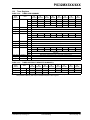
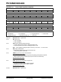
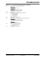
26.2
26.2.5
Watchdog Timer and Power-Up
Timer Operation
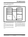
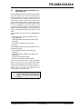
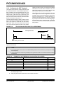
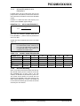
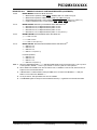
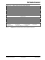
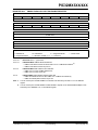
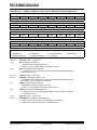
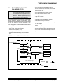
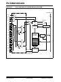
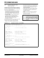
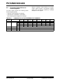
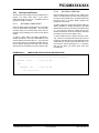
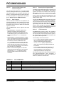
This describes the operation of the Watchdog Timer
operation and the Power-Up Timer
26.2.1
WATCHDOG TIMER OPERATION
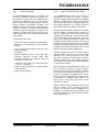
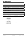
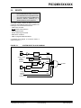
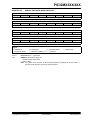
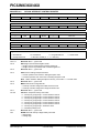
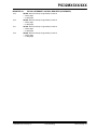
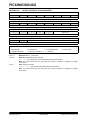
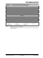
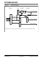
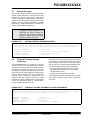
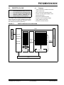
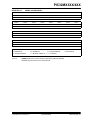
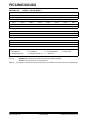
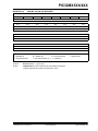
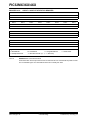
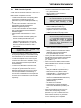
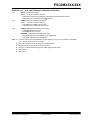
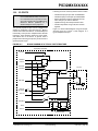
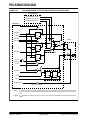
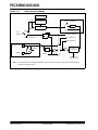
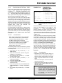
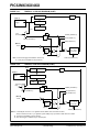
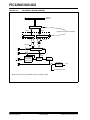
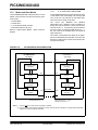
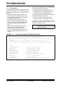
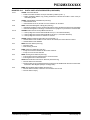
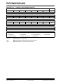
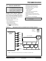
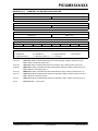
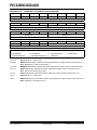
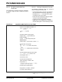
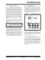
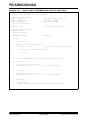
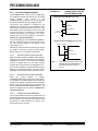
If enabled, the WDT will increment until it overflows or
“times out”. A WDT time-out will force a device Reset,
except during Sleep or Idle modes. To prevent a WDT
time-out Reset, the user must periodically clear the
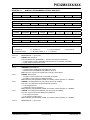
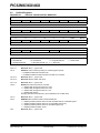
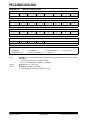
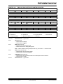
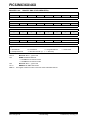
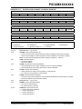
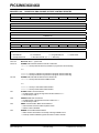
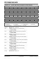
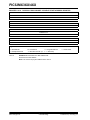
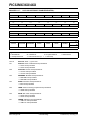
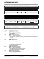
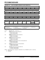
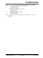
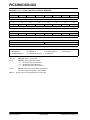
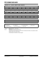
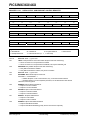
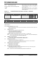
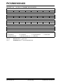
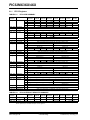
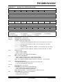
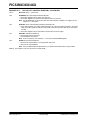
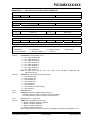
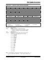
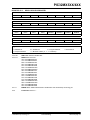
Watchdog Timer by setting the WDTCLR
(WDTCON<0>) bit.
WDT OPERATION IN POWER SAVE
MODES
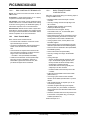
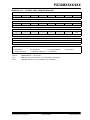
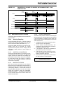
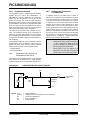
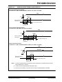
The WDT, if enabled, will continue operation in Sleep or
Idle modes. The WDT may be used to wake the device
from Sleep or Idle. When the WDT times out in a Power
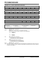
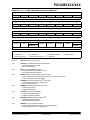
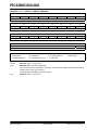
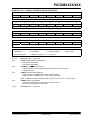
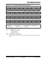
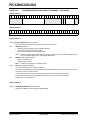
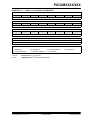
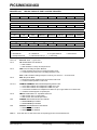
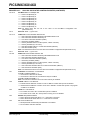
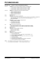
Save mode, a Non-Maskable Interrupt (NMI) is generated and the WDTO (RCON<4>) bit is set. The NMI
vectors execution to the CPU start-up address but does
not reset registers or peripherals. If the device was in
Sleep, the SLEEP (RCON<3>) status bit will also be
set. If the device was in Idle, the IDLE (RCON<2>) status bit will also be set. These bits allow the start-up
code to determine the cause of the wake-up.
The WDT uses the LPRC oscillator for reliability.
Note:
26.2.2
The LPRC is enabled whenever the WDT
is enabled.
ENABLING AND DISABLING THE
WDT
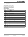
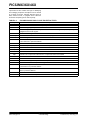
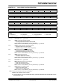
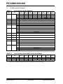
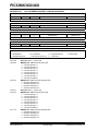
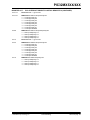
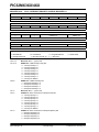
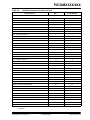
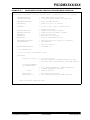
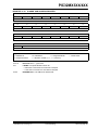
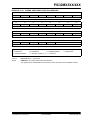
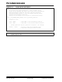
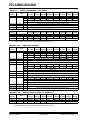
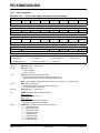
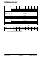
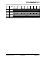
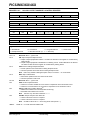
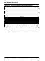
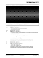
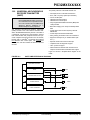
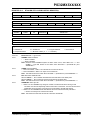
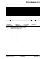
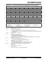
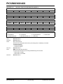
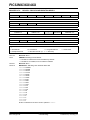
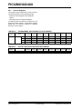
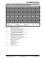
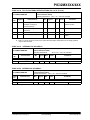
The WDT is enabled or disabled by the device configuration or controlled via software by writing to the
WDTCON register.
26.2.3
DEVICE CONFIGURATION
CONTROLLED WDT
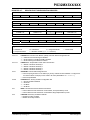
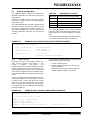
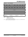
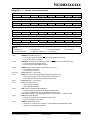
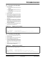
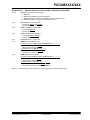
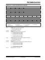
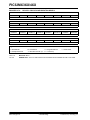
If the FWDTEN Configuration bit is set, then the WDT
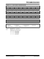
is always enabled. The WDT ON control bit
(WDTCON<15>) will reflect this by reading a ‘1’. In this
mode, the ON bit cannot be cleared in software. This bit
will not be cleared by any form of Reset. To disable the
WDT in this mode, the configuration must be rewritten
to the device.
Note:
26.2.4
The default state for the WDT on an
unprogrammed device is WDT enabled.
26.2.6
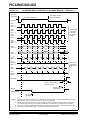
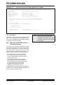
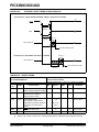
There will be a time delay between the WDT event in
Sleep and the beginning of code execution. The duration of this delay consists of the Start-up time for the
oscillator in use and the Power-Up Timer delay, if it is
enabled.
Unlike a wake-up from Sleep mode, there are no time
delays associated with wake-up from Idle mode. The
system clock is running during Idle mode; therefore, no
start-up delays are required at wake-up.
26.2.7
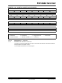
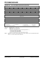
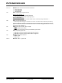
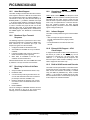
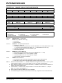
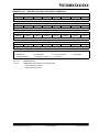
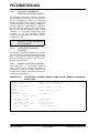
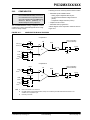
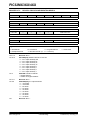
The WDT is enabled in software by setting the WDT
ON control bit. The WDT ON control bit is cleared on
any device Reset, The bit is not cleared upon a wake
from Sleep or exit from Idle mode. The software WDT
option allows the user to enable the WDT for critical
code segments and disable the WDT during noncritical
segments for maximum power savings. This bit can
also be used to disable the WDT while the part is
awake to eliminate the need for WDT servicing, and
then re-enable it before the device is put into Idle or
Sleep to wake the part at a later time.
© 2008 Microchip Technology Inc.
RESETTING THE WDT TIMER
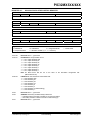
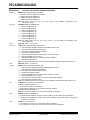
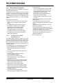
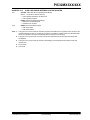
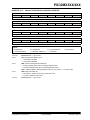
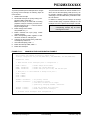
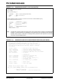
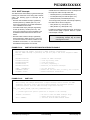
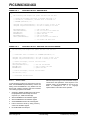
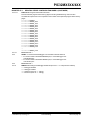
The WDT is reset by any of the following:
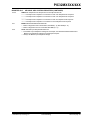
• On ANY device Reset
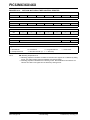
• By a WDTCONSET = 0x01 or equivalent
instruction during normal execution.
• Execution of a DEBUG command
• Exiting from Idle or Sleep due to an interrupt
Note:
SOFTWARE CONTROLLED WDT
If the FWDTEN Configuration bit is a ‘0’, then the WDT
can be enabled or disabled (the default condition) by
software. In this mode, the ON (WDTCON<15>) bit
reflects the status of the WDT under software control.
A ‘1’ indicates the WDT is enabled and a ‘0’ indicates it
is disabled.
TIME DELAYS ON WAKE
26.2.8
The WDT timer is not reset when the
device enters a Power Save mode. The
WDT should be serviced prior to entering
a Power Save mode.
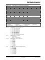
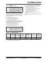
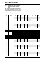
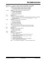
WDT TIMER PERIOD SELECTION
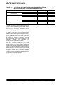
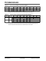
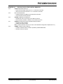
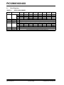
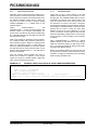
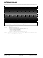
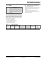
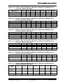
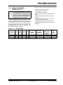
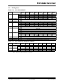
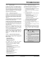
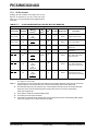
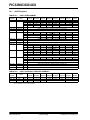
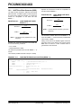
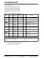
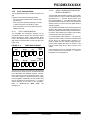
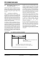
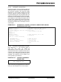
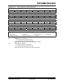
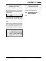
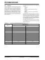
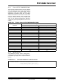
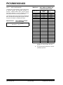
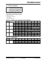
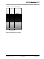
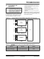
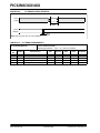
The WDT clock source is the internal LPRC oscillator,
which has a nominal frequency of 32 kHz. This creates
a nominal time-out period for the WDT (TWDT) of 1
millisecond when no postscaler is used.
Note:
Preliminary
The WDT time-out period is directly
related to the frequency of the LPRC
oscillator. The frequency of the LPRC
oscillator will vary as a function of device
operating
voltage and temperature.
Please
refer
to
the
specific
PIC32MX3XX/4XX device data sheet for
LPRC clock frequency specifications.
DS61143D-page 561