1
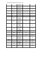
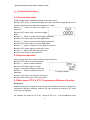
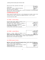
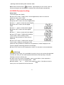
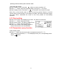
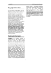
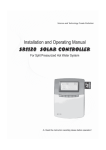
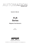
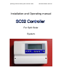
Operating manual for Solar system controller: SC02
Document Number: GD7.3-03
Installation and Operating manual
For Split Solar
System
Operating manual for Solar system controller: SC02
Document Number: GD7.3-03
Contents
1. Safety information ..................................................................................................................... 1
1.1 Installation and commissioning ....................................................................................... 1
1.2 About this manual ............................................................................................................ 1
1.3 Liability waiver................................................................................................................ 1
1.4 Important remark ............................................................................................................. 2
1.5 Signals Description.......................................................................................................... 2
2. Installation and Connection ....................................................................................................... 3
2.1 Controller installation ...................................................................................................... 3
2.2 Appearance and Wiring Terminal .................................................................................... 4
2.2.1 Appearance ........................................................................................................... 4
2.2.2 Wiring terminal..................................................................................................... 5
2.3.1 Pressure sensor...................................................................................................... 6
2.3.2 Temperature sensor.......................................................................................... 6
3. Descriptions of menu and system .............................................................................................. 7
3.1 Menu structure:................................................................................................................ 7
3.2 Menu description ............................................................................................................. 7
3.3 System description........................................................................................................... 9
3.3.1 Solar circuit pump (Pump) (See details in 4.3)..................................................... 9
3.3.2 Auxiliary heater (Heater) (See details in 4.4 tHET).............................................. 9
3.3.3 Curtain control (Curtain) (See details in 4.7 COVE)............................................ 9
4.Controller functions..............................................................................................................11
4.1 Access main menu ..........................................................................................................11
4.2 Access sub-menu ............................................................................................................11
4.3 Main menu DT O & DT F Temperature difference function ..........................................11
4.3.1 Setup the switch-on temperature difference: ...................................................... 12
4.3.2 Setup the switch-off temperature difference:...................................................... 12
4.4 Main menu - THET timing heating ............................................................................... 12
4.4.1 Setup the switch-on first timing heating: ............................................................ 13
4.4.2 Setup the switch-off first timing heating: ........................................................... 14
4.4.3 Setup the switch-on second timing heating: ....................................................... 14
4.4.4 Setup the switch-off second timing heating:....................................................... 14
4.4.5 Setup the switch-on third timing heating:........................................................... 15
4.4.6 Setup the switch-off third timing heating: .......................................................... 15
4.5 TEMP Temperature main menu ..................................................................................... 15
4.5.1 EMOF Collector emergency shutdown function activated................................. 16
4.5.2 EMON Collector emergency shutdown function exit......................................... 16
4.5.3 CMX Maximum limited collector temperature (collector cooling function)...... 17
4.5.4 CMN low temperature protection of collector.................................................... 18
4.5.5 CFR frost protection of collector ........................................................................ 18
4.5.6 SMX Maximum temperature of tank.................................................................. 19
4.5.7 REC Tank re-cooling function ............................................................................ 19
4.5.8 C- F Celsius and Fahrenheit temperature transferring ........................................ 20
4.6 COVE Curtain control ................................................................................................... 20
4.6.1 T1MX T1 max value set ..................................................................................... 20
4.6.2 T1RD T1 return difference set ............................................................................ 21
4.6.3 T2MX T2 Max value set..................................................................................... 21
4.6.4 T2RD T2 return difference set ............................................................................ 21
4.7 DVWG Anti-Legionella function .................................................................................. 21
4.8 HND Manual mode........................................................................................................ 22
Operating manual for Solar system controller: SC02
4.8.1 HND1 manual (Pump) ..................................................................................... 22
4.8.2 HND2 manual (Heater).................................................................................... 22
4.8.3 HND3 manual (Curtain) ..................................................................................... 22
4.9 PASS Password setting .................................................................................................. 23
4.10 LOAD Recovery factory setting .................................................................................. 24
4.11 Manual heating ............................................................................................................ 24
4.12 Holiday function .......................................................................................................... 24
4.13 Clock setting ................................................................................................................ 25
4.14 Temperature query function......................................................................................... 25
5. Protection function .................................................................................................................. 26
5.1 Memory protection ........................................................................................................ 26
5.2 Screen protection ........................................................................................................... 26
6. Trouble shooting ...................................................................................................................... 27
6.1 Trouble protection.......................................................................................................... 27
6.2 Trouble checking ........................................................................................................... 27
7. Quality Guarantee.................................................................................................................... 29
8. Technical data .......................................................................................................................... 29
9. Packing list .............................................................................................................................. 30
10. Optional parts list................................................................................................................... 30
-2-
Operating manual for Solar system controller: SC02
Document Number: GD7.3-03
1. Safety information
1.1 Installation and commissioning
• When laying cables, please ensure that no damage occurs to any of the constructional
fire safety measures presented in the building.
• The controller must not be installed in rooms where easily inflammable gas mixtures
are present or may occur.
• The permissible environmental conditions can’t be exceeded at the site of installation.
• Before connecting the device, make sure that the energy supply matches the
specifications that controller requires.
• All devices connected to the controller must conform to the technical specifications of
the controller.
• All operations on an open regulator are only to be conducted cleared from the power
supply. All safety regulations for working on the power supply are valid.
• Connecting and /or all operations that require opening the regulator (e.g. changing the
fuse) are only to be conducted by specialists.
1.2 About this manual
This manual describes the installation, function and operation of a solar thermal
controller.
When installing the remaining components e.g. the solar collectors, pump assemblies
and the storage unit, are sure to observe the appropriate installation instructions
provided by each manufacturer. Only trained professional personnel may only perform
installation, electrical connection, commissioning and maintenance of the device. The
professional personnel must be familiar with this manual and follow the instructions
contained herein.
1.3 Liability waiver
The manufacturer cannot monitor the compliance with these instructions or the
circumstances and methods used for installation, operation, utilization and maintenance
of this controller. Improper installation can cause damages to material and persons.
This is the reason why we do not take over responsibility and liability for losses,
damages or cost that might arise due to improper installation, operation or wrong
utilization and maintenance or that occurs in some connection with the aforementioned.
Moreover we do not take over liability for patent infringements or infringements –
occurring in connection with the use of this controller- on third parties rights. The
manufacturer preserves the right to put changes to product, technical date or
-1-
Operating manual for Solar system controller: SC02
installation and operation instructions without prior notice. As soon as it becomes
evident that safe operation is no longer possible (e.g. visible damage). Please
immediate take the device out of operation. Note: ensure that the device cannot be
accidentally placed into operation.
1.4 Important remark
We have carefully checked the text and pictures of this manual and provided the best of
our knowledge and ideas, however inevitable errors maybe exist. Please note that we
cannot guarantee that this manual is given in the integrity of image and text, they are
just some examples, and they apply only to our own system. Incorrect, incomplete and
erroneous information and the resulting damage we do not take responsibility.
1.5 Signals Description
Safety instructions:This is a warning signal, it will cause personal injury and
safety risks. Operating steps: Please follow this mark: “►”.Note:This signal
means important operating or functional information!
-2-
Operating manual for Solar system controller: SC02
2. Installation and Connection
2.1 Controller installation
Please combine the fixing plate with the back of controller, make sure it is fixed.
Note: 1.Self-tapping screw and Expansion pipe can be used for fixing to the wall.
The hole size isφ7mm.
2.If you fix the controller to the water tank or other metal plate, the Self-tapping
screw is the best choice. The hole size isφ3mm.
Fixing plate
Self-tapping screw & Expansion pipe
-3-
Operating manual for Solar system controller: SC02
2.2 Appearance and Wiring Terminal
2.2.1 Appearance
-4-
Operating manual for Solar system controller: SC02
2.2.2 Wiring terminal
Note:FU1 is a 2A/240V fuse (this is protection for controller, does not matter with the output)
Catalog
Power
Input
Code
Power1
Power supply 1
Power2
Power supply 2
Pr
Signal
Input
T1
T2
T3
Outputs
Name
Description
AC240V/50Hz/The power is determined by the
outputs of both Heater and Pump
DC12V/The power is determined by the output
of Curtain
Contact protection(can be
connected to pressure
protection switch)
Temperature sensor of the
collector
Temperature sensor at the
bottom of the tank
Temperature sensor at the
top of the tank
Protection mode runs in open circuit, normally
works in short circuit
PT1000
NTC10K
NTC10K
Heater
Auxiliary heater
AC240V/Max. current limitation :10A
Pump
Circulation pump
AC240V/ Max. current limitation :3A
Curtain
Overheating protection
DC12V/ Max. current limitation :10A
Note:Power2 should be powered by UPS with Li battery is recommended to ensure
power-off protection function is on. Once main power failed, the battery will take over
main power for curtain to move on the “Cover” position.
-5-
Operating manual for Solar system controller: SC02
2.3 Descriptions of Signal Input
2.3.1 Pressure sensor
Sensor connector: R1/4”
Connector: waterproof.
Connecting pressure: 0.22±0.05Mpa
Cut off pressure: 0.18±0.05Mpa
Maximum pressure: 1.2Mpa
Temperature range: -30℃~120℃
2.3.2 Temperature sensor
PT1000 sensor is required for “T1”, suitable for any weather condition, temperature
resistant:280℃, does not matter for the positive and negative.
NTC10K,B=3950 are required for T2 and T3, material is PVC, temperature
resistant:105℃, does not matter for the positive and negative.
Remove the device from the mains supply before opening the case A
potentially defective sensor can be checked using an ohmmeter. To do this,
the sensor must be disconnected, its resistance measured, and the value
compared with the figures in the table below, small deviation (±1%) is
acceptable.
PT1000 resistance value
℃
0
10
20
Ω 1000 1039 1077
30
1116
40
1155
NTC 10K B=3950 resistance value
℃
0
10
20
30
Ω
33620 20174 12535 8037
50
1194
40
5301
60
1232
50
3588
70
1270
60
2486
80
1309
70
1759
90
1347
80
1270
90
933
100
1385
100
697
All sensor cables carry low voltage, and to avoid inductive effects, must not be
laid close to 230 volt or 400-volt cables (minimum separation of 100mm)
If external inductive effects are existed, e.g. from heavy current cables, overhead train
cables, transformer substations, radio and television devices, amateur radio stations,
microwave devices etc. Then the cables to the sensors must be adequately shielded.
Sensor cables may be extended to a maximum length of ca. 100 meter, when cable’s
2
length is up to 50m, and then 0.75mm cable should be used. When cable’s length is up
2
to 100m, and then 1.5mm cables should be used.
-6-
Operating manual for Solar system controller: SC02
3. Descriptions of menu and system
Please connect the sensor to the input ports and pump or switch valve to the
output ports before supplying the main power. You can set the time,
password and other dates which related to the system when the power on.
3.1 Menu structure:
Sub-menu can set more details, please know more about it.
3.2 Menu description
Code
(main menu)
Code(submenu)
DT O
DT F
THET
tH1o
tH1F
Instruction
Switch-on
temperature
difference
Switch-off
temperature
difference
Timing heating
Timing
heating(first
timing on)
Timing
-7-
State as delivered
Corresponding
chapter
8℃
4.3.1
4℃
4.3.2
4.4
04:00,40℃
4.4.1
05:00,45℃
4.4.2
Operating manual for Solar system controller: SC02
tH2o
tH2F
tH3o
tH3F
TEMP
EMOF
EMON
CMX
CMN
CFR
SMX
REC
C-F
COVE
T1MX
T1RD
T2MX
heating(first
timing off)
Timing
heating(second
timing on)
Timing
heating(second
timing off)
Timing
heating(third
timing on)
Timing
heating(third
timing off)
Temperature
Collector
maximum
switch-off
temperature
Collector
maximum
switch-on
temperature
Maximum
temperature of
collector
(Collector
cooling function)
Low
temperature
protection of
collector
Frost protection
of collector
Maximum
temperature of
tank
Tank re-cooling
function
Celsius and
Fahrenheit
temperature
transferring
Temperature to
cover
Collector temp.
setting
Collector temp.
difference
setting
T2 temp. setting
-8-
10:00,50℃
4.4.3
10:00,55℃
4.4.4
17:00,50℃
4.4.5
22:00,55℃
4.4.6
4.5
130
4.5.1
120
4.5.2
110
4.5.3
4.5.4
4.5.5
60
4.5.6
OFF
4.5.7
4.5.8
4.6
100
4.6.1
10
4.6.2
80
4.6.3
Operating manual for Solar system controller: SC02
T2RD
DVWG
HND
HND1
HND2
HND3
PASS
LOAD
T2 temp.
difference
setting
Anti
legionnaires'
function
Manual
controlling
Heater Manual
controlling
Pump Manual
controlling
Curtain Manual
controlling
Password
setting
Recovery to
factory set
5
4.6.4
OFF
4.7
4.8
OFF
4.8.1
OFF
4.8.2
OFF
4.8.3
0000
3.3 System description
3.3.1 Solar circuit pump (Pump) (See details in 4.3)
The solar circuit pump (Pump) is switched on as soon as the switch-on temperature
difference (△T on) between the collector array (T1) and the storage tank (T2) is
reached. If the temperature difference between the collector array (T1) and storage tank
(T2) drops below the switch-off temperature difference, or the temperature of storage
tank (T3) reaches the preset maximum storage temperature, then the solar circuit pump
(R1) is switched off.
3.3.2 Auxiliary heater (Heater) (See details in 4.4 tHET)
Within the preset time section of back-up heating, if the temperature T3 is below the
switch-on temperature, then the circulation pump ( H1) of back-up heating is triggered,
when T3 is heated to the switch-off temperature, circulation pump H1 of back-up
heating is ceased.
3.3.3 Curtain control (Curtain) (See details in 4.7 COVE)
When T1 or T2 above the setting, the curtain will cover; below the setting, the curtain
will not cover.
When the “Power1” off, output “-、+” the curtain will cover;
When the “Pr” off, output “-、+”
the curtain will cover
-9-
Operating manual for Solar system controller: SC02
Pr:Protection terminal (protection when
the pressure off)
T1: Collector temp. sensor: PT1000
T2: Tank temp. sensor(down): NTC10K
T3: Tank temp. sensor(upside): NTC10K
Heater:Auxiliary heater
Pump: Circuit pump
Curtain:Curtain
-10-
Operating manual for Solar system controller: SC02
4.Controller functions
4.1 Access main menu
Under standby status, doing like following access main menu
►Press “SET” button, “PWD 0000”displays on screen, the left first digital blinks, ask for
entering password, factory default set password is “ 0000”
►Press “+”“-” button to enter first digital of
password.
►Press “SET” button again, the second digital
blinks
►Press “+”“-” button, to enter second digital of password
►Press “SET” button again, the third digital blinks
►Press “+”“-” button to enter the third digital of password
►Press “SET” button again, the fourth digital blinks
►Press “+”“-” button, to enter the fourth digital of password
►Press “SET” button again to access main menu
►Press “+”“-” button, can select the main menu
►Press “ESC” button to exit main menu
4.2 Access sub-menu
After selecting main menu, do like following access submenu
►Press “SET” button, to access submenu
►Press “+”“-” button to select submenu
►Press “SET” button again to access
program,can adjust parameter value now
►Press “+”“-” button, to adjust the value of
parameter
For example: submenu
►Press “ESC” button, exit program of submenu
►Press “ESC” button again, to exit main menu.
4.3 Main menu DT O & DT F Temperature difference function
Description:
Solar circuit pump P1 is triggered by the temperature difference function, so long as the
temperature difference between collector and tank reaches the switch-on DT, solar
circuit pump is triggered.
For example: the switch-on DT is 8℃, switch-off DT is 4℃, if the temperature in the
-11-
Operating manual for Solar system controller: SC02
bottom part of tank is 20℃, then just when collector temperature rises up to 28℃, pump
is triggered, and when collector temperature drops to 24℃, pump is ceased.
Note: the switch-on/off DT of 8 ℃ and 4 ℃ are standard system setting according to
many years’ experience, only in special application cases it needs to be changed, (e.g
far distance heat transferring), normally it is recommend to use default set. Switch-on
and switch-off DT are alternating set. To avoid mistake the minimum difference
between two temperature differences (∆T on –∆T off) is set as 2℃.
4.3.1 Setup the switch-on temperature difference:
Under standby status, access main menu DT O,
►Press “SET” button, to access settings program of DT O, “DT O 08℃” displays on
screen, “08℃” blinks, the switch-on temperature difference can be set.
►Press “+”“-” button, to adjust the value of switch-on DT, adjustable range
(OFF+2℃)~20℃, factory setting is 8℃
►Press “ESC” button to exit this setting,
parameter is saved automatically.
4.3.2 Setup the switch-off temperature difference:
Under standby status, access main menu DT F
►Press “SET” button, to access settings program of DT F, “DT F 04℃” displays on
screen, “04℃” blinks, the switch-off temperature difference can be set.
►Press “+”“-” button to adjust the value of
switch-off
DT,
adjustable
range
0℃ ~
(ON-2℃),factory set is 4℃.
►Press “ESC” to exit menu, or wait for 20
seconds to exit automatically, the setup
parameters are saved automatically.
4.4 Main menu - THET timing heating
Description:
Electrical heater, gas boiler or oil boiler can be integrated into solar system used as
back-up of system, and they can be triggered automatically at preset time by preset
temperature. Within a preset time section, when the temperature (T3) of top part of
tank drops below the preset switching-on temperature of this function, back-up heating
starts to work, when T3 rises up to the preset turning off temperature, back-up heating
is stopped. Within 24 hours, three time sections can be set with this controller.
Factory set:
The first time section: back-up heating function starts at 4:00 and ends at 5:00 am.
Within this time section, switch-on temperature is 40℃, switch-off temperature is 45℃.
The second time section: from 10:00 to 10:00 am, it means there is no back-up heating
-12-
Operating manual for Solar system controller: SC02
in this time.
The third time section: back-up heating function starts at 17:00 and ends at 22:00 pm.
Within this time section, the switch-on temperature is 50℃, switch-off temperature is
55℃.
The switch-on temperature adjustable range: 10℃ ~ (OFF-2 ℃)
The switch-off temperature adjustable range: (ON+2 ℃) ~ 80℃
If you want to shut off one timing heating, then you can set the turning on time and
turning off time same value (for example, the second time section no this function, then
you can set turning on/off time is 10:00 ~ 10:00)
When time is outside of the preset time section, back-up heating doesn’t work
automatically even when the tank temperature reaches the switch –on temperature of
heating.
Note:
z When there is no sensor installed in the top part of tank (no T3 sensor), controller
will take the signal of T2 (sensor in bottom of tank) automatically to control this
function.
z
The time in this controlled is 24 hours, when you set time section, the switch-off
time of heating should be larger than switch-on time. For example: if you set the
switch-on time of heating is at 17:00, but switch-off time of heating is 6:00, then this
setting doesn’t take effect, that means within this time section, heating function
doesn’t work. The correct set is like flowing: it should be divided into two time
sections, one time section is from 17:00 to 23:59, the other time section is from
00:00 to 06:00.
4.4.1 Setup the switch-on first timing heating:
Under standby status, access main menu tHET
►Press “SET” button, access THET program to set parameter, “tH 1o 04:00” displays
on screen, the switch-on time and temperature for first time section of heating function
can be set
►Repress “SET” button, “04” of hour time blinks on
screen
►Press “+”“-” button to adjust hour of time
►Repress “SET” button again, “00” of minute time blinks on screen
►Press “+”“-” button to adjust minute of time
►Repress “SET” button, temperature “40℃” blinks on screen
►Press “+”“-” button, to set the switch-on temperature of heating
►Then, Press “ESC” to exit this set and to access the switch-off time and temperature
-13-
Operating manual for Solar system controller: SC02
set
4.4.2 Setup the switch-off first timing heating:
►Press “+” button, “tH 1F 05:00” displays on screen, the switch-off time and
temperature for first time section of heating function can be set
►Press “SET” button, “05” of hour time blinks on screen.
►Press “+”“-” button to adjust hour of time
►Repress “SET” button, “00” of minute time
blinks on screen
►Press “+”“-” button to set minute of time
►Repress “SET” button, temperature “45℃” blinks on screen
►Press “+”“-” button, to set switch-off temperature of heating
►Press “ESC” to exit this set program, parameters are saved automatically
-------------------------------------------------------------------------------------------------------------------
4.4.3 Setup the switch-on second timing heating:
►Press“+” button, “tH 2o 10:00” displays on screen, the switch-on time and
temperature for the second time section of heating function can be set
►Press “SET” button, “10” of hour time blinks on screen
►Press “+”“-” button to adjust hour of time
►Repress “SET” button, “00” of minute time
blinks on screen
►Press “+”“-” button to adjust minute of time
►Repress “SET” button, temperature “50℃” blinks on screen
►Press “+”“-” button to adjust switch-on temperature of heating
►Then press “ESC” to exit this set and to access the switch-off time and temperature
set
4.4.4 Setup the switch-off second timing heating:
►Press “+” button, “tH 2F 10:00” displays on
screen, set the switch-off time and temperature
of second time section of heating function
►Press “SET” button, “10” of hour time blinks
on screen
►Press “+”“-” button to adjust hour of time
►Repress “SET” button, “00” of minute time blinks on screen
►Press “+”“-” button to adjust minute of time
-14-
Operating manual for Solar system controller: SC02
►Repress “SET” button, temperature “55℃”blinks on screen
►Press “+”“-” button, to adjust switch-off temperature of heating
► Press “ESC” to exit this set program, parameter is saved automatically
------------------------------------------------------------------------------------------------------------------
4.4.5 Setup the switch-on third timing heating:
► Press “+” button, “tH 3o 17:00” displays on screen, set the switch-on time and
temperature of the third time section of heating function
►Press “SET” button, “17” of hour time blinks
on screen
►Press “+”“-” button, to adjust hour of time
►Repress “SET” button, “00” of minute time
blinks on screen
►Press “+”“-” button, to adjust minute of time
►Repress “SET” button, temperature “50℃” blinks on screen
►Press “+”“-” button, to adjust switch-on temperature of heating
►Press “ESC” to exit this set program and to the switch-off time and temperature set
4.4.6 Setup the switch-off third timing heating:
►Press “+” button, “tH 3F 22:00” displays on screen, the switch-off time and
temperature of the third time section of heating function can be set
►Press “SET” button, “22” of hour time blinks on screen
►Press “+”“-” button, to adjust hour of time
►Repress “SET” button, “00” of minute time
blinks on screen
►Press “+”“-” button to adjust minute of time
►Repress “SET” button, temperature “55℃” blinks on screen
►Press “+”“-” button to adjust switch-off temperature of heating
►Press “ESC” to exit menu, or wait for 20 seconds, set parameters are saved
automatically
Note: when no gas or oil boiler is installed in system, electrical heater can be installed
as back-up device, when electrical heater is in operation status, signal
blinks on
screen.
If customer use electrical heater as back-up, please according to the power of electrical
heater to equip corresponding safety devices.
4.5 TEMP Temperature main menu
For every system, the factory set parameters are in the best condition that is fully
integrated into the entire solar system. But these parameters can also be set
-15-
Operating manual for Solar system controller: SC02
individually to cater the special requirements, please carefully observe the operation
data of system components after setting.
Note: parameters that can be set depend on the selected system, not all the
parameters can be adjusted in a solar system.
Following submenu can be access though TEMP main menu.
4.5.1 EMOF Collector emergency shutdown function activated
Function description:
When collector temperature rises up to this maximum switch-off limited temperature
(EM), this function is activated, solar circulation pump is stopped in order to avoid the
damage of system other components caused by high temperature. The adjustable
range of EMOF temperature is ( 120 ℃ ~ 200 ℃ ), factory set is 130 ℃ . If the
temperature of collector rises up to EMOF limited temperature, solar circuit pump is
ceased, but when collector temperature drops emergency shutdown exit temperature
EMON(factory set is 120℃), solar circuit pump will be reset, and this function is
deactivated.
Setup steps:
to access main menu TEMP, then select submenu EMOF (see 4.1 and 4.2), “EMOF
130℃” displays on screen
►Press“ SET” button, parameter “130 ℃ ”
blinks.
►Press “ +,-“ button, to adjust this maximum
switch-off temperature, adjust range (ON+3
℃)~200 ℃, factory set is 130 ℃
►Repress “SET” button to activate and deactivate this function, if deactivate the
function, “EMOF - - -” displays on screen.
► Press “ESC” button to exit menu or wait for 20 seconds to exit automatically, set
parameters are saved automatically.
4.5.2 EMON Collector emergency shutdown function exit
Setup steps:
to access main menu TEMP, then select
submenu EMON (see 4.1 and 4.2), “EMON
120℃” displays on screen
►Press “SET” button, parameter “120℃” blinks.
►Press “ +,-“ button, to adjust this maximum exit temperature, adjust range (OF-3
℃)~200 ℃, factory set is 120℃
►Repress “SET” button to activate and deactivate this function, if deactivate the
function, “EMON - - -” displays on screen.
-16-
Operating manual for Solar system controller: SC02
► Press “ESC” button to exit menu or wait for 20 seconds to exit automatically, set
parameters are saved automatically.
When these two signals of EM blink on the screen, it indicates this
function is in activated, and at this moment temperature of tanks reaches
to its maximum limited temperature
When only this signal of EM blinks on the screen, it indicates this function is also
activated, but temperature of tank doesn’t reach to its maximum limited
temperature
4.5.3 CMX Maximum limited collector temperature (collector cooling function)
Function description:
The collector cooling function delays the vaporization of the heat transfer fluid. Shortly
before reaching the maximum temperature of the collector, the solar pump starts
working in order to cool down the heat transfer fluid using the heat losses occurring in
pipelines and storage cylinder.
When tank temperature rises to its preset maximal temperature, solar circuit pump is
ceased compulsively even the temperature difference is satisfied. If the sunshine is very
good, as a result collector temperature will rise continuously, when collector
temperature rises up to its maximal temperature, solar pump will be triggered again
even at the case that tank temperature is already to its maximal temperature. And solar
pump works until the temperature of collector drops since this reversed circulation or
when tank temperature rises its emergency temperature (95℃).
When
displays, and
blinks on the screen, it indicates that tank emergency
temperature reaches, tank temperature is ≥95℃
Setup steps:
To access main menu TEMP, then select submenu CMX “CMX 110℃” displays on
screen
►Press “SET” button, parameter “110℃” blinks.
►Press “+”“-” button, to adjust the collector
protection temperature, adjustable range
(100℃~190℃), factory set is 110℃
►Repress “SET” button, activate and deactivate this function, if deactivate the function,
“CMX - - -” displays on screen.
►Press “ESC” button to exit the menu or wait for 20 seconds to exit automatically,
parameters are saved automatically.
CMX signal displays on screen, it indicates that this function is in activated.
-17-
Operating manual for Solar system controller: SC02
4.5.4 CMN low temperature protection of collector
Description:
When the temperature of collector is below preset CMN temperatures, solar circuit
pump is ceased, even when the temperature difference between collector and tank
exceeds switch-on temperature difference, solar pump doesn’t work yet. When
temperature of collector is 3℃ higher that the preset CMN temperature, solar circulation
pump is restarted, controller exits this program.
Setup steps:
To access main menu TEMP, then select submenu CMN, “CMN - - -” displays on screen,
default set is off.
►Press “SET” button, default off signal “- - -”
blinks on screen.
►Repress “SET” button, to activate and
deactivate this function
►Press “+”“-” button, to adjust the low protection temperature of collector CMN,
adjustable range (00℃~90℃), after activate the function, factory set is 10℃
► Press “ESC” button to exit the menu or wait for 20 seconds to exit automatically,
parameters are saved automatically.
CMN signal displays on screen, it indicates that this function is in activated.
4.5.5 CFR frost protection of collector
Description:
In winter when the temperature of collector is below the preset frost protection
temperature (factory set is 4℃), Solar circuit pump is triggered. Besides when tank
temperature (T2) drops to 4℃, electrical heater is triggered automatically and it is in
operation until T2 is heated up to 20 ℃ or it is stopped when program of CFR is exited.
When collector temperature rises up to 7 ℃, solar circuit pump is ceased, program of
CFR exits automatically.
This function is used in system, which use water as heat transfer liquid, to avoid the
freezing of solar heat transfer fluid.
Setup steps:
To access main menu TEMP, then select
submenu CFR, “CFR - - -” displays on screen,
default set is off.
►Press “SET” button, default off “- - -” blinks.
►Repress “SET” button, to activate or
deactivate this function
►Press “+”“-” button, to adjust the frost protection function, adjustable range is
-18-
Operating manual for Solar system controller: SC02
(-10℃~10℃), after function activated, default set is 4℃
► Press “ESC” button to exit the menu or wait for 20 seconds to exit automatically,
parameters are saved automatically.
CFR signal displays on screen, it indicates that this function is in activated.
Note: this function is only available in special solar system which using no-anti-freezing
liquid; this kind of system is only suitable in area where the ambient temperature is near
to 0℃ in only few days. If safety requirement is very high, then anti-freezing is
necessary, we suggest using suitable anti-freezing liquid to avoid frost problem.
4.5.6 SMX Maximum temperature of tank
Description:
When the DT between collector T1 and Tank 2 caters the switch-on DT of circulation,
solar pump is triggered, but in order to avoid the high temperature inside tank, controller
will check whether the temperature (T3) of top part of tank is higher than maximum
temperature of tank, when T3 is higher than preset SMX temperature, solar pump is
ceased even at the case that DT caters condition. When tank temperature drops and is
2℃ below the SMX, solar pump restarts when DT caters condition.
Setup steps:
To access main menu TEMP, then select submenu SMX, “SMX 60℃” displays on
screen.
►Press “SET” button, parameter “60℃”blinks
►Press “+”“-” button to adjust the value of
maximum temperature of tank1 adjustable
range is(2℃~95℃), default set is 60℃
►Repress “SET” button to activate and deactivate this function, if function deactivated,
“SMX - - -” displays on the screen.
► Press “ESC” button to exit the menu or wait for 20 seconds to exit automatically,
parameters are saved automatically.
SMX signal displays on screen, it indicates that this function is in activated.
4.5.7 REC Tank re-cooling function
Description:
If tank temperature is over tank’s maximum temperature, and at the same time,
collector temperature is 5℃ lower than tank temperature, then solar pump is triggered,
through this reversed circulation, tank temperature is reduced by heat loss occurs in
collector, solar pump keep in working until tank temperature drops below its maximum
temperature.
-19-
Operating manual for Solar system controller: SC02
Setup steps:
To access main menu TEMP, then select
submenu REC, “REC OFF” displays on screen,
default set is off.
►Press “SET” button, parameter “OFF” blinks
on screen
►Repress “SET” button to activate or deactivate this function, after function activated;
factory set is “REC ON”
► Press “ESC” button to exit the menu or wait for 20 seconds to exit automatically,
parameters are saved automatically.
REC signal displays on screen, it indicates that this function is in activated.
4.5.8 C- F Celsius and Fahrenheit temperature transferring
Setup steps:
To access main menu TEMP, then select submenu C-F, “C-F ℃” displays on screen.
►Press “SET” button, parameter “℃” blinks on the screen.
►Press “+” button, to select between Celsius and Fahrenheit temperature, factory set is
℃
►Press “ESC” button to exit menu or wait for 20 seconds to exit automatically,
parameters are saved automatically.
4.6 COVE Curtain control
Description:
When the T1 or T2 reach the setting(T1MX、T2MX), output“-、+” screen display
“COVER”, when the T1 or T2 below the setting(T1MX-T1RD、T2MX -T2RD), output
“+、-” screen display “UNCOVER”.
4.6.1 T1MX T1 max value set
Select T1MX(T1 max value set)sub-menu, the screen display “T1MX 100℃”, factory
set:“100℃”
►Press “SET” button, the “100℃” blinks on screen
►Press “+”“―” button, adjust the T1 max
temperature setting, the range is (60℃~150℃)
►Press “ESC” button to quit the menu, or wait for
20 seconds to exit automatically, parameters are
saved automatically.
-20-
Operating manual for Solar system controller: SC02
4.6.2 T1RD T1 return difference set
Select T1RD(T1 return difference set) sub-menu, the screen display“T1RD 10℃”,
factory set:“10℃”
►Press “SET” button, the “10℃” blinks on screen
►Press“+”“―” button, adjust T1 return difference
set, the range is (5℃~30℃)
► Press “ESC” button to quit the menu, or wait
for 20 seconds to exit automatically, parameters
are saved automatically.
4.6.3 T2MX T2 Max value set
Note: the value of T2MX must less than T1MX.
Select T2MX(T2 max value set) sub-menu, the screen display “T2MX 80℃”, factory
set:“80℃”
► Press “SET” button, the “80℃” blinks on screen
►Press “+”“―” button, adjust the T2 max
temperature setting, the range is (40℃~99℃)
► Press “ESC” button to quit the menu, or wait for
20 seconds to exit automatically, parameters are
saved automatically.
4.6.4 T2RD T2 return difference set
Select T2RD(T2 return difference set) sub-menu, the screen display“T2RD 5℃”, factory
set:“5℃”
► Press “SET” button, the “5℃” blinks on screen
► Press“+”“―” button, adjust T2 return difference
set, the range is (5℃~30℃)
► Press “ESC” button to quit the menu, or wait for
20 seconds to exit automatically, parameters are
saved automatically.
4.7 DVWG Anti-Legionella function
Description:
In order to avoid occurring bacteria in water tank when the temperature of tank is lower
for a long time, controller will check the temperature of tank every 7 days in a period
automatically, if the temperature of tank is never over 70oC during this period, then at
the factory set default time of 01:00 on the seventh day of the period auxiliary heating
system is triggered automatically to heat water until it rises up to 70oC, bacteria is killed
by high temperature, where after function is deactivated.
Setup steps:
To access main menu FUN, then select submenu DVWG, “DVWG OFF” displays on
screen. Default set is “OFF”.
-21-
Operating manual for Solar system controller: SC02
►Press “SET” button, parameter” OFF” blinks
on the screen.
►Repress“+”“-”button, “DVWG ON” blinks on
the screen, function is triggered.
►Press “ESC” button to exit the menu or wait for 20 seconds to exit automatically,
parameters are saved automatically.
4.8 HND Manual mode
When using this controller first time or when debugging this controller, output of this
controller (Pump, Heater, Curtain)can be triggered manually. “On, OFF” control.
To access main menu HND
----------------------------------------------------------------------------------------------------------------
4.8.1 HND1
manual (Pump)
► Press “SET” button, “HND1 off” displays on the
screen, “Pump” output manually set
► Repress “SET” button, “HND1 on” displays on
the screen, “Pump” output is switched-on
► Repress “SET” again, “HND1 off” displays,
“Pump” output is switched-off
► Press “ESC” to exit “Pump” set program
-------------------------------------------------------------------------------------------------------------------
4.8.2 HND2
manual (Heater)
►Press “+” button, “HND2 off” displays on the
screen, “Heater” output manually set
►Press “SET” button, “HND2on” displays on the screen, “Heater” output is switched-on
►Repress “SET” again, “HND2off” displays, “Heater” output is switched-off
►Press “ESC” to exit “Heater” set program
-------------------------------------------------------------------------------------------------------------------
4.8.3 HND3 manual (Curtain)
►Press “+” button, “HND3 off” displays on the screen, “Curtain” output manually set
►Press “SET” button, “HND3 on” displays on the
screen, “Curtain” output is switched-on
►Repress “SET” again, “HND3 off” displays, “Curtain”
output is switched-off
► Press “ESC” to exit “Curtain” set program
--------------------------------------------------------------------------------------------------------------------22-
Operating manual for Solar system controller: SC02
Note: When manual mode is
activated,signal displays on the screen, after 15
minutes all outputs are switched-off, controller exits manual mode automatically.
4.9 PASS Password setting
Setup steps:
To access main menu PASS,
►Press “SET” button, “PWDC 0000”, the left digital blinks, ask for to enter the
password, factory set is “0000”
►Press “+”“-” button to enter the first digital
►Repress “SET” button, the second digital blinks
►Press “+”“-” button to enter the second digital
►Repress “SET” button, the third digital
blinks
►Press “+”“-” button to enter the third digital
►Repress “SET” button, the fourth digital
blinks
►Press “+”“-” button to enter the fourth digital
►Press “SET” button, “PWDN 0000” displays
on the screen, ask for entering a new
password, doing as above to enter the new
password
►Press “SET” button, “PWDG 0000” displays
on the screen, asking for reentering the new
password, doing as above to reenter the new password, “PWOK” displays on the
screen to indicate reentering password successfully.
►Press “ESC” button to exit set program or wait for 20 seconds to exit automatically.
Warning!
If the password is forgot, it is not possible to recover, but you can recover the password
to factory set, then you can reedit a password like above descript steps, doing like
following to recover to factory set.
► Open cover in the front of the display, press
and hold on, then repress the
recovery button, which on the display plate.
►Buzzer makes “du - - -” 3 times, then release
factory set, a new password can be reset now.
-23-
button. Controller recovers to
Operating manual for Solar system controller: SC02
4.10 LOAD Recovery factory setting
Setup steps:
To access main menu REST,
►Press “SET” button, “YES” displays on the
screen.
►Hold down “SET” button, buzzer makes“du - - -”3 times, then release “SET” button.
Controller recovers to factory set, new parameters can be reset now.
►Press “ESC” button to exit set program or wait for 20 seconds to exit automatically.
4.11 Manual heating
Description:
Electrical heater, gas or oil boiler can be as back-up devices in a solar system, this
controller can achieve constant temperature controlling, when controller gets
temperature signal of top part tank (T3) is 2℃ below the preset temperature, back-up
heating will be triggered. When temperature of top part tank (T3) reaches to the preset
temperature, heating is ceased.
Conditions for triggering manual heating function: the setting temperature should be 2℃
higher than tank temperature.
Activate/deactivate the function:
►Press “Heating” button, temperature “60℃” blinks on the screen.
►Press “+”“-” button to adjust switch-on temperature, adjustable range 10℃~80℃,
factory set is 60℃.
After 20 seconds, this function is activated, signal
heating signal
displays on the screen, and
blinks also.
►Press “Heating” button again, to switch-off manual heating function.
Note: Manual heating can only heat tank one time, after manual heating is triggered,
when temperature of tank rises up to the preset temperature, manual heating ceases,
and manual heating function will be deactivated automatically, if customer wants to heat
again, you need redo according to above steps.
4.12 Holiday function
Description:
When this function is running, the curtain is under “cover” state avoiding the
over-heating problem.
Please run this function when:
-You will go for a holiday or not at home for a long time;
-No requirement of using hot water for a long time.
-24-
Operating manual for Solar system controller: SC02
Run/Close this function:
►Press “Holiday” button 3 seconds,
blinks on screen as well as “07”.
►Press “+”“―” button, adjust the days for holiday, the range is “1―60” days.
►Press “Holiday” button 3 seconds, no
on the screen, this function is closed.
Note: Only on this function when no stay at home long period, Ensure to exit this
function when you back home!! If over 60days of holiday, shut down main power supply
and water source, meanwhile the curtain on the cover position as over-heating
protection.
4.13 Clock setting
►Press “clock” button, time displayed on screen, “00” blinks for HOUR set.
►Press “+”“―” button, adjust the HOUR.
►Press “Clock” button, “00” blinks for MINUTE set
►Press “+”“―” button, adjust the MINUTE.
►Press “ESC” button to exit setting program or
wait for 20 seconds to exit automatically.
4.14 Temperature query function
Under standby status,
►Press “+”“-” button and check the value of temperature sensors T1~ T3
When checking temperature, T1 – T3 will displays one by one, corresponding sensor
signal
blinks.
-25-
Operating manual for Solar system controller: SC02
5. Protection function
5.1 Memory protection
In case power failure occurs, the controller keeps the parameter settings unchanged.
5.2 Screen protection
When no any press on button for 3 minutes, screen protection is activated automatically,
and then LCD lighting lamp is switched-off. Through press any button to light LCD lamp
again.
-26-
Operating manual for Solar system controller: SC02
6. Trouble shooting
6.1 Trouble protection
When there is a break or short circuit between the connection of temperature sensors,
controller switches off the corresponding functions and no more output signals are
given, at the same time error signals
are showed on the display.
If control unit does not work correctly, please check following points.
Error message on
LCD screen
Output state
Meaning
Heater
Pump
Curtain
T1 - - -
T1 sensor problem
√
×
“-、+”
T2 - - -
T2 sensor problem
√
×
“-、+”
T3 - - -
T3 sensor problem
×
√
√
Power1 (been Cut-off)
×
×
“-、+”
×
×
“-、+”
E4
Pr (Open circuit)
Note:“√” means run automatically, “×” means no output. “-、+”means curtain on the
cover position.
6.2 Trouble checking
The controller is quality product, conceived for years of continuous trouble-free
operation. If a problem occurs, the cause of the problem very often lies not in the
controller but in the peripheral components. The following description of some
well-known problems should help the installer and operator to isolate the problem, so
that the system can be place back into operation as quickly as possible and to avoid the
unnecessary costs. Of course, not all possible problems can be listed here. However,
most of the normal problems encountered with the controller can be found in the list
below, only return the controller to seller when you are absolutely sure that none of the
problems listed below is responsible for the fault.
-27-
Operating manual for Solar system controller: SC02
Symptoms
Secondary symptoms
Possible cause
Procedure
Controller does not
Display shows
Controller power
Check the controller
appear to function
nothing, no display
supply is interrupted
power cable
at all
illumination
or program is out of
Press reset button
work
The solar pump
The pump symbol in
Pump power supply is
Check the pump power
doesn’t operate,
the display blinks
interrupted
cable
Pump doesn’t
The pump symbol in
The maximum
No fault
operate
the display doesn’t
storage tank
blink.
temperature (SMX)
despite the fact that
switch-on conditions
are satisfied
Lighted
has been reached
The maximum
or
blinks
collector temperature
(EM) has been
reached.
T1- - -
Fault (short circuit or
On the controller,
open circuit) in a
request the current
temperature sensor
values from all
Error message
connected temperature
displays on the
sensors, replace all
screen
defective sensors and /or
cabling.
The solar pumps
The pump symbol in
Holiday function or
No problem, it is normal.
operated, despite
the display blinks.
Frost protection
If necessary to
the fact that the
function or tank
deactivate the
switch-on conditions
re-cooling function is
corresponding functions.
are not satisfied.
activated.
One function can’t
There is no function
All inputs and outputs
be activated
selection in submenu
are used; inputs and
outputs can’t be used
doubly.
-28-
No fault on controller
Operating manual for Solar system controller: SC02
7. Quality Guarantee
Manufacturer provides following quality responsibilities to end-users: within the period
of quality responsibilities, manufacturer will exclude the failure caused by production
and material selection. A correct installation will not lead to failure. When a user takes
incorrect handling way, incorrect installation, improper or crud handling, wrong
connection of sensor in system and incorrect operation, the quality responsibility is
invalid for them. The warrantee expires within 12 months after the date of purchasing
the controller.
8. Technical data
Parameter Name
data
Dimension
Power supply
Power dissipation
Temperature measurement
Accuracy
Collector temperature
measurement range
Tank or piping temperature
measurement range
Circulation pump
Heating booster
Input signal
200mm*146mm*45mm
AC220V±10%
< 3W
±2℃
Output signal
Temperature condition
Waterproof level
-10~220℃
0~110℃
3pcs , ≤ 300W
1pcs , ≤ 1500W
Collector: 1pcs PT1000 sensor cable 500oC (Silicon
wire≤280℃)
Water tank: 2pcs NTC10K, B=3950 sensor ≤135℃
(PVCwire≤105℃)
Pressure protection: ≥0.22Mpa-on ,≤0.18Mpa-off
Output port(Heater):AC240V, 10A.
Output port (Pump):AC240V, 3A.
Output port (Curtain):DC12V, 10A.
-10~50℃
IP40
-29-
Operating manual for Solar system controller: SC02
9. Packing list
Parts
Quantity
Solar controller(SC02)
User manual
PT1000 sensor (φ6*50mm, cable
length:1.5m)
NTC10K(φ6*50mm, cable length:1.5m)
Pressure sensor
Plastic expansion pipe
Flat-head screw
1pcs
1pcs
1pcs
2pcs
1pcs
4pcs
4pcs
10. Optional parts list
Parts
Power supply with
adapter and Li
Battery
Power Plug
Size
AC240V-DC12V/2A,
for max. 5*HFC-2-S
AC240V-DC12V/5A,
for max 12*HFC-2-S
AC240V-DC12V/10A,
for max 25*HFC-2-S
AC240V
-30-
Picture
Picture