Download DUAL MAST MOBILE ELEVATING WORK

Transcript
R
Zhejiang Dingli Machinery Co., Ltd
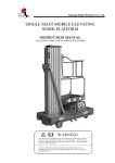
DUAL MAST MOBILE ELEVATING
WORK PLATFORM
INSTRUCTION MANUAL
(For GTWY6-2000/ GTWY8-2000/GTWY10-2000/ GTWY12-2000)
WARNING
THE MANUFACTURER SHALL NOT BE HELD LIABLE IN CASE OF
FAULTS OR ACCIDENTS DUE TO NEGLIGENCE, INCAPACITY,
INSTALLATION BY UNQUALIFIED TECHNICIANS AND IMPROPER
USE OF THE MACHINE
DO NOT OPERATE THIS MACHINE UNTIL YOU READ AND
UNDERSTAND ALL THE DANGERS,WARNINGS AND CAUTIONS
IN THIS MANUAL
Contents
Chapter 1
Preface…………………………………………………………
1
Chapter 2
Specification……………………………………………………
1
Chapter 3
Safety information……………………………………………..
2
Chapter 4
Plates and Warning Labels……………………………………..
3
Chapter 5
Transport and set up…………………………………………… 13
Chapter 6
Operation guide………………………………………………... 16
Chapter 7
Maintenance guide…………………………………………….. 18
Chapter 8
Battery…………………………………………………………
Chapter 9
Trouble shooting……………………………………………….
Chapter 10
Construction drawing, Electrical schematic
24
and Hydraulic diagram…………………………………………
22
23
December 2008
Instruction Manual
Chapter 1
Preface
Read this manual carefully before the machine is taken into use to avoid errors.
Correct operations and regular inspections are factors of vital importance for the
operating economy and lifetime of the machine.
These important parts are described in the following related sections.
Alloy aluminum mast mobile elevating work platform is the most ideal
equipment for aerial work. Dual mast mobile elevating work platform is
intended to move one or two persons along with their necessary tools and
materials to working position where they will carry out work on the work
platform.
They are generally intended for use on plane and level floors. They are mainly
used for business decoration, industrial facilities maintenance, lamps and
lanterns replacement in halls, maintenance of street lamps, aerial photography
and wall cleaning etc.
The dual mast mobile elevating work platform has the following characteristics:
1.1 Lift or fall steadily: The seamless transmission is used between the lifting
masts, thus minimizing the amount of sway after lifting.
1.2 Safe and reliable: The four turning stabilizers of the unit connected to the
four corners of the chassis support the MEWP during work. They are designed
for leveling regulation and preventing inclination. They are composed of stand
bars and turning legs. The stand bars are installed in the turning legs. Extending
out the turning legs before operating the unit enlarges the area of supporting.
Therefore, the steadiness of the whole platform is guaranteed.
1.3 Convenient: The whole work platform is light because the lifting masts are
made of alloy aluminum. The structure is compact and the volume is small, so
only one or two persons can move the equipment and carry it through a very
narrow passage.
All the information contained in this booklet is based on the data available at the
time of printing; the manufacturer reserves the right to modify its products at
any time, without notice and without liability. It is therefore advisable to
regularly check for any changes.
Chapter 2
Specifications
Technical specifications and major dimensions are shown in Table 1 and Figure
1, respectively.
Table 1
Model
The number Platform
Max.
Max.
Rated of persons
size
platform working
load allowed on
height
height
A×B
platform
Power
rating
Outrigger
footprint
C×D
AC
DC
Stored
dimension
L×W×H
Machine
weight
mm
mm
kg
Person(s)
mm
mm
kw
mm
kg
GTWY6-2000
6000
7700
325
2
1090×600
1690×1650
0.75~1.5 1.5
1440×840×1800
500
GTWY8-2000
8000
9700
300
2
1210×600
1880×1770
0.75~1.5 1.5
1560×840×1920
570
GTWY10-2000
10000
11700
300
2
1450×600
2230×1960
0.75~1.5 1.5
1790×840×1920
728
GTWY12-2000
12000
13700
200
2
1450×600
2550×2570
0.75~1.5 1.5
1790×890×2140
825
DL-GTWY(TWIN) SERIES
page1
December 2008
Instruction Manual
Figure 1
Chapter 3
Safety information
Even if you are familiar with other types of mobile elevating work platforms,
read the following matters needing attention for safe and effective operation:
3.1 Only the trained and qualified are permitted to operate this machine. Always
use safety belt and helmet when aerially working.
3.2 If you are subject to dizziness or seizures, or are bothered by heights, you
must not operate this type of machinery.
3.3 An operator must not use drugs or alcohol that can change his/her alertness
or coordination. An operator on prescription or over-the-counter drugs needs
medical advice on whether or not he/she can safely operate machines.
3.4 Make sure understand all the safety rules and instructions on plates and
warning labels before operating the machine.
3.5 This machine is designed to use on flat and hard ground only. If the ground
is uneven, you must adjust supporting bolts to make sure the chassis is on level.
Don’t work with force if the conditions for using the equipment are not met.
3.6 Forbid to park the mobile elevating work platform (MEWP) on a slope.
When traveling on slope, make sure there are no personnel or obstructions in
front of the moving direction. Move at a safety speed. Don’t turn quick on a
slope.
DL-GTWY(TWIN) SERIES
page2
December 2008
Instruction Manual
3.7 Ensure all stabilizers are engaged properly before elevating the platform.
3.8 In the course of lifting and falling or in lift situation, masts and platform
must not collide with any obstacles or moving objects and you must not move it.
3.9 Do not move the whole unit with electricity.
3.10 It is prohibited of getting on and off the work platform when elevated.
3.11 Keep clear of live electric conductors.
3.12 Don’t lift if it is overload. The machine can’t be used as a crane.
3.13 The manual force on the work platform should not exceed 400N.
3.14 Operating this machine should conformance with local national regulations.
3.15 Any unsafe operation patterns on the platform are strictly forbidden.
3.16 Unless in an emergency, the personnel on the ground mustn’t operate the
lower control device if they do not receive orders from those are aerially
working.
3.17 Don’t allow people stand or pile up things under the raised platform.
3.18 when operating the machine in a dusty environment, you should take
protective measures to prevent the graininess debar is stirred into the moving
parts, which can causing damage ,thus extend the span of the machine life
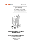
3.19 Don’t change, modify or abandon the safety devices in any way. If there is
an uncertain problem, don’t dismantle the machine, inform the dealer for help.
3.20 Don’t set the devices increasing the work height arbitrarily.
3.21 Any additions that would increase the wind load on the machine, e.g. notice
boards, are strictly forbidden.
3.22 Any special working methods or conditions beyond those specified by the
manufacturer shall obtain the guidance and written approval of the manufacturer.
3.23 The optimal using period is within 5 years, reassess the performance of the
machine then and contact the manufacturer for better advice.
Chapter 4
Plates and Warning Labels
Upon unpacking, check the plates and warning labels. Do not operate the
machine on which the plates or labels are missing or illegible. Contact the dealer
immediately.
The following plates and warning labels are visible on the machine.
● Nameplate
DL-GTWY(TWIN) SERIES
page3
December 2008
Instruction Manual
● Operating instructions
Brief Operating Instruction
●Leveling the whole equipment
1. Pull up the aligning pin, extend outwards the turning leg, which is connected to one
of the four corners of the chassis, until the aligning pin gets into the working aligning
hole automatically.
2. Turn the handle clockwise until the supporting foundation contacts the ground for
all the four bolts, go on turning to make the road wheel away from the ground.
3. Adjust the leveling by observing the spirit level on the chassis. The bubble should
move to the center circle of the gauge when the chassis is set on an even plane.
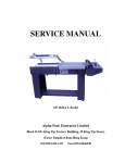
4. To store the turning stabilizers of the unit, turn the handle counterclockwise until the
supporting foundation away from the ground. Pull up the aligning pin, retract
inwards the turning leg until the aligning pin gets into the storing aligning hole.
●Installation and removal of the guardrail
1. After connecting to the electrical supply, lift the platform about 1.2m. (Higher than
the height of the guardrail)
2. Stretch out the two movable brackets mounted on the sides of the masts.
3. Intermittently press “DOWN” button. The guardrail will rest against the brackets
but the platform will continue to descend to the lowest position.
4. Screw the four bolts on the lower basket of guardrail into the holes of the connecters
for platform. Make sure the guardrail and platform were held together and finish its
installation.
5. When finishing the work or going through low passageways, fall the guardrail and
the removal course of the guardrail is the inverse course of its installation.
●How to use the control buttons
1. Before operating the machine, all circuit breakers and the leakage breaker must be
in “ON” position on the electrical box panel.
2. The mobile elevating work platform uses two sets of upper and lower parallel control
devices.
3. On either control panels, press “UP” button for lifting and press “DOWN” button
for lowering the platform.
4. The platform rises or falls when the button is pressed. Upon loosening the buttons
the platform stops.
5. A big mushroom-shaped button is the stopping button at emergency. Press it only if
the platform can’t stop effectively in the course of rising. Reset the button by turning
the knob in the direction shown by the arrow. Do not pull the knob.
●Emergency Operation
If two sets of the upper and the lower control devices can’t make the platform fall
because of sudden power failure or other causes, turn the valve counterclockwise and
the platform will be lowered slowly. Once the platform falls down to the bottom, the
valve for emergency should be closed.
Emergency Operation
If two sets of the upper and the lower control devices can’t make the platform
fall because of sudden power failure or other causes, turn the valve
counterclockwise and the platform will be lowered slowly. Once the platform
falls down to the bottom, the valve for emergency should be closed.
DL-GTWY(TWIN) SERIES
page4
December 2008
Instruction Manual
● Warning labels
DL-GTWY(TWIN) SERIES
page5
December 2008
Instruction Manual
DL-GTWY(TWIN) SERIES
page6
December 2008
Instruction Manual
DL-GTWY(TWIN) SERIES
page7
December 2008
Instruction Manual
DL-GTWY(TWIN) SERIES
page8
December 2008
Instruction Manual
DL-GTWY(TWIN) SERIES
page9
December 2008
Instruction Manual
GTWY SERIES DECAL INSPECTION(TWIN)
DL-GTWY(TWIN) SERIES
page10
December 2008
Instruction Manual
GTWY SERIES DECAL INSPECTION(TWIN)
Part No.
Description
QTY.
9121011
DC control panel
1
9121013
Control panel on electric box
1
9121015
Control panel on work platform
1
9221011
Machinery label
1
9321011
Emergency operation
1
9321013
Leveling and justment(lift)
2
9321015
Leveling and justment(right)
2
9323013
Gate of platform
1
9323015
Label--Down
1
9323017
Label--Stop
1
9323019
Label—Up
1
9323021
Notice—Screw
4
9323023
Brief operating instruction
2
9323025
Notice—Leveling the whole equipment
2
9341011
Label—Back-up
1
9421017
Danger—Collision hazards
or Tip-over hazard
1
9421019
Caution—Electrocution hazard
1
9421021
Warning—Make sure to position the stabilizers before operating
4
9421025
Warning—Turn on the switches.(For AC)
1
9421027
Max. Load on each stabilizer—4000N
4
9422021
Warning—Make sure the chock is in place during maintenance
1
9422023
Warning—Shearing danger, keep hands away
1
9423021
Notice—Allowed number of persons: TWO
1
9423025
Max. Allowed wind speed—10.7m/s
1
9423027
Warning—Keeping safe clearance with live electric conductors
1
9423029
Caution—The masts or the platform must not bump into any barrier or moving
object during lifting
1
9423031
Warning—Ensure all atabilizers are engaged properly before elevating the
platform
1
9423033
Warning—The manual forces applied by persons on the work platform should
not exceed the permltted limit when it is raised
1
9423035
Danger—Any unsafe operation pattern on the platform is strictly forbidden
1
Decal Inspection:
Use the pictures on the next page to verify that all decals are legible and in place.
Below is a numerical list with quantities and descriptions.
DL-GTWY(TWIN) SERIES
page11
December 2008
Instruction Manual
GTWY SERIES DECAL INSPECTION(TWIN)
Part No.
Description
QTY.
9423037
Danger—Don′t move the whole equipment when in the course of lifting and
lifted
1
9423039
Danger—The addition of any device, such as ladder, to increase the working
height is strictly not allowed.
1
9423041
Danger-- Don′t park at the slope, pay attention to the obstacle when moving at
the slope.
1
9423043
Capacity—250kg(FOR 10 m)
1
9423045
Capacity—300kg(FOR 6、8 m)
1
9423047
Max. Allowed manual force—400N
1
9441011
CE label
1
9441021
Danger—Please don′t stand
1
9443011
Capacity—200kg(FOR12 m)
9443015
Warning—Operating Instruction
1
9443017
Notice—The charging socket of the battery (For DC)
1
9443019
Notice—Recharging lasts at least 12 hours (For DC)
1
9443021
Notice—Please cut off the power after operating (For DC)
1
9443023
Label—Directional arrows
1
Decal Inspection:
Use the pictures on the next page to verify that all decals are legible and in place.
Below is a numerical list with quantities and descriptions.
DL-GTWY(TWIN) SERIES
page12
December 2008
Instruction Manual
Chapter 5
Transport and set up
5.1 Transport and Storage
5.1.1 Moving the equipment
5.1.1.1The platform should fall down to the bottom when you are moving the
equipment to other working places and then retract the turning stabilizers. The
supporting foundations should be made away from the ground and then push the
whole machine to the destination. If the equipment goes across the uneven
ground, the supporting foundations should be away from the ground so far as to
prevent the bolt from bending by the obstacles.
5.1.1.2 If the platform is carried in a long distance, other loading tools should be
used for transportation. A forklift should be used for loading onto other vehicles.
It should be lifted upward from the bottom. The sketch below shows the lifting
points and method of loading.
Note: Pull the plug of the power supply out of the socket when you move the
whole equipment, cut off the power supply to avoid any unnecessary accidents.
5.1.2 Storage of the equipment
If you plan to stop using the equipment for a long time, the unit should be
cleaned and protected by a dustproof cover (supplied).
5.2 Set up
5.2.1 Inspection on Opening the Packaging
For the initial use, most users should remove the outer packing of wood box for
equipment, shockproof and knock-preventing packing before using the
equipment, Even if without outer packing, check the whole equipment and its
accessories, and the equipment includes the following parts.
DL-GTWY(TWIN) SERIES
page13
December 2008
Instruction Manual
Dustproof Cover
User’s Manual
Certificate of Quality
1
–Front Steering Wheel; 2–Chassis; 3–Hydraulic Unit Cover;
4–Emergency Lowering Device; 5–Hydraulic Power Pack;
6–Turning Stabilizer; 7–Rear Wheel; 8–Electrical Box;
9–Connecting Bolt; 10 –Guardrail; 11–Upper Control Device;
12–Platform; 13–Connecter; 14–Movable Bracket; 15–Platform
Bracket; 16–Ladder; 17–Supporting Bars;
18 –Masts Assembly
Note: 1.If the unit has been damaged during transport, it must not be put into
service, and you should immediately contact your dealer.
2. The equipment has been lubricated before delivery, and the hydraulic unit has
been filled with hydraulic oil.
3. If a battery has been supplied with the machine, the battery is charged.
Check that the acid level is correct in each cell and that the specific gravity is in
order (see “Battery”).
5.2.2 Area Needed For Set up the Machine
The area for machine stabilizer footprint shown as the sketch below:
C
D
mm
mm
GTWY6-20000
1650
1690
2
GTWY8-20000
1770
1880
3
GTWY10-20000
1960
2230
4
GTWY12-20000
2570
2550
Item
Model
1
DL-GTWY(TWIN) SERIES
page14
December 2008
Instruction Manual
5.2.3 Supporting and Leveling the Unit
There are horizontal forces including operating force and outer wind force etc.
on the platform. If excessive, render the platform unstable. Preventing
inclination of the unit is achieved by extending the four turning stabilizers,
which are connected to the four corners of the chassis. Supporting and leveling
the unit is achieved by adjusting the support bolts of the four turning stabilizers.
The sketch below shows the following parts:
The instructions for operation are as follows:
1.Pull up the aligning pin, extend outwards the turning leg, which is connected
to one of the four corners of the chassis, until the aligning pin gets into the
working aligning hole automatically.
2.Turn the handle clockwise until the supporting foundation contacts the ground
for all the four bolts, go on turning to make the road wheel away from the
ground.
3.Adjust the leveling by observing the spirit level on the chassis. The bubble
should move to the center circle of the gauge when the chassis is set on an even
plane.
4.To store the turning stabilizers of the unit, turn the handle counterclockwise
until the supporting foundation gets away from the ground. Pull up the aligning
pin, retract inwards the turning leg until the aligning pin gets into the storing
aligning hole.
Warning! You must observe the spirit level on the chassis. The bubble should
be within the center circle of the gauge.
Warning! Once you doubt leveling is incorrect, just base on mast and use
rectangle level gauge to verify it.
Warning! Forbid any operation without extending out all the turning stabilizers.
5.2.4 Installation and removal of the guardrail
The guardrail of platform is movable. During transportation or passing narrow
passages, make the whole guardrail fall till it doesn’t take up the height space.
DL-GTWY(TWIN) SERIES
page15
December 2008
Instruction Manual
The following figure shows the guardrail and its installation.
5.2.4.1 Steps of installation
1.After connecting to the power supply, lift the platform and guardrail up
together about 1.2 m. (higher than guardrail height).
2. Stretch outwards the two movable brackets mounted on the sides of the masts.
3. Intermittently press the DOWN button. The guardrail will rest against the
movable brackets but the platform continues to fall down to the bottom. The
guardrail is in the working position now.
4.Turn the four connecting bolts on the lower basket of the guardrail into the
connecters of the platform. Make sure the guardrail and the platform were held
together and finish its installation.
5.2.4.2 Removing the guardrail
When finishing the work or going through a low passageway, the guardrail
should be removed from the platform. The course of removing the guardrail is
the inverse course of its installation.
Chapter 6
Operation Guide
6.1 The relevant conditions of using the equipment
6.1.1 The surface of work ground should be flat and hard with no obstacles in air
and the safety distance between the equipment and high-tension line is adequate.
6.1.2 The environment temperature should be within -10℃~38℃; Height above
sea level ≤1000 m.
6.1.3 The environment humidity≤90%.
6.1.4 Electrical power: AC 230V±10%, 50Hz.
6.1.5 The wind power is not more than Beaufort Scale 5 (the speed of wind is
10.7 m/s).
6.1.6 The noise grade of this machine is 72~74 dB while operation.
Notes:
1)Prevent the sunlight from directly shining onto the hydraulic and electrical
units of the equipment if the environment temperature is above 32℃.
2) If the conditions mentioned above are not met, please contact with your
supplier and take the relevant guarantee measures for using the equipment.
DL-GTWY(TWIN) SERIES
page16
December 2008
Instruction Manual
6.2 Control Panel function and Description
6.2.1 AC Control Panel
Control panel on electric box
1.
2.
3.
4.
5.
6.
Circuit breaker
Leakage breaker
Control circuit breaker
Power indicator
Up button
Down button
Control panel on work platform
6.2.2 DC Control Panel
1. Voltage indicator
2. On/Off key
3. Fuse
4. Emergency stop switch
5. Up button
6. Down button
6.3 Installation of Power Plug
Put the power plug into the power socket at the
job site in accordance with the rated requirement.
Note:
Prior to installation, the rating of the power
source must be confirmed.
6.4 How to use the control buttons
6.4.1 Before operating the machine, all circuit breakers and the leakage breaker
must be in “ON” position on the electrical box panel
6.4.2 The mobile elevating work platform has two sets of controls. one at the
base of the unit and the other on the work platform itself
6.4.3 On either control panels, press “Up” button for lifting and press “Down”
button for lowering the platform.
6.4.4 The platform will be raised or lowered so long as the appropriate button is
depressed. The platform will stop in position as soon as the button is released.
6.4.5 Emergency stop: A big mushroom-shaped button is provided at each
control panel for emergency stop. This should be used only when other means to
DL-GTWY(TWIN) SERIES
page17
December 2008
Instruction Manual
stop the platform moving fails. Reset the button by turning the knob in the
direction shown by the arrow. Do not pull the knob.
Note: The lower controls is installed on the electrical box, control its key. The
key should be taken away if it is not in use so as to prevent unauthorized
personnel from using it.
6.5 Emergency Operation
In the event of power cut-off or other
reasons and the platform fails to descend
using both the upper and lower controls, an
emergency device consisting of a release
valve located at the side of the chassis is
used to lower the platform. Turn the valve
counterclockwise and the platform will be
lowered slowly. Once the platform has
descended to its lowest position, the valve
should then be closed securely.
Note: The above shows the diagram of the emergency release valve.
Chapter 7
Maintenance Guide
7.1 Control check
For the initial use or use after long periods of storage or changes in
environmental conditions. Check should be made on power supply, hydraulic oil,
and lubricants to confirm that they are all in well condition.
Caution!
Special attention should be paid to check all safety devices of this machine
before using it:
1.Emergency stop switches
There are two emergency stop switches on the machine. Please check the
function of these two emergency stop switches. Stop to use this machine and
inform the manufacturer/agent immediately if they cannot work normally.
2.Emergency release valve
There is an emergency release valve on this machine to lower the platform in the
event of power cut-off or other reasons and the platform fails to descend using
both the upper and lower controls.
Please check the function of the emergency release valve. Stop to use this
machine and inform the manufacturer/agent immediately if it cannot work
normally.
7.2 Check before operation
Before you begin your workday, you must inspect your machine and report all
deficiencies. Do not operate the machine until deficiencies are corrected and all
systems are in good operational condition.
1. Check for missing, damaged or unreadable safety signs.
2. Check for broken, missing, damaged or loose parts, especially the screws and
nuts on both sides of the masts.
DL-GTWY(TWIN) SERIES
page18
December 2008
Instruction Manual
3.
4.
5.
6.
7.
Check pivot pins for damaged or missing retaining devices.
Check oil level in the tank.
Check hydraulic system for leakage and damage.
Check for cracked welds and other evidence of structural damage.
Check if the supporting foundations rotate freely around the supporting bolts,
lubricate if necessary.
8. Lubricate positions as mentioned in 7.5 if necessary.
9. Check if there is an abnormal noise or tremble when starting the machine.
10. Secure connection of power or battery plug.
11. Perform necessary maintenance procedure outlined by the manufacture.
7.3 Periodical examinations and tests
This MEWP should be examined and tested according to the following items
every 3 months.
1. Lubricate the lifting chain. Check the chain for wear.
2. Check and tighten possible loose screws and nuts.
3. Check brush wear in the pump motor, and replace those worn so that a good
contact is maintained.
4. Visual examination of the structure with special attention to corrosion and
other damage of load-bearing parts and welds.
5. Examination of the mechanical, hydraulic, and electrical systems with
special attention to safety devices as mentioned in clause 7.1.
Note: The frequency and extent of periodical examinations and tests may also
depend on national regulations.
7.4 Maintenance
7.4.1 Adjusting the maximum rising force
The proper pressure of hydraulic system has been preset at the factory, however,
the regulating value has been changed because of using the product for a long
term.
Notes:
1) When you find the rising force not reach the rated value, open the hydraulic
unit cover. Please refer to the above sketch, turn the regulating valve 1 of the
hydraulic control device clockwise till the rising rated value.
DL-GTWY(TWIN) SERIES
page19
December 2008
Instruction Manual
2) If necessary, a pressure gauge (supplied as an optional attachment) could be
connected to the emergency lowering valve block for hydraulic system pressure
checking.
7.4.2 Adjusting the speed of falling
The speed of falling of the platform can also be adjusted.
Note: Please refer to above sketch. The speed is reduced when you turn the
adjusting screw 2 of “throttle valve ”clockwise, otherwise, the speed is
increased.
7.4.3 Fluid level checking
A separate fluid level indicator is provided as an attachment (optional) for both
the permissible maximum fluid level and the necessary minimum level when the
machine is in transports.
7.4.4 Replacing the hydraulic oil
The hydraulic oil of the equipment should be replaced once after the equipment
has been used for half a year to clear off the pollution caused by wearing of the
system in the first term. Determine the term of the replacement according to the
polluted circumstances of the hydraulic oil later (suggest replacing the hydraulic
oil once every one and half one years).
Note:
1) Selecting of the hydraulic oil depends directly on influence of the temperature
for using. For non-paramo region, the common hydraulic oil of kinematic
viscosity (40) 46mm2/s (the nominal value) is recommended for use.
2) When replacing the hydraulic oil, first place a basin for containing waste oil
under the oil box. Open the oil filler cap 6 at the top of the oil box and then
remove the oil drain plug 5 at the bottom. After draining off the waste oil, fill a
little clean hydraulic oil into the oil box through the oil filler hole and wash it.
Tighten the drain plug 5 after all the oil has been drained. Then fill up with clean
hydraulic oil and allow for a slight overflow to displace any air.
7.4.5 Regulating the transmission chain
The direct result of wearing the transmission chain is to stretch the total length
of the chain. Measure the stretching rate of the used transmission chain by eye
every three months. The mast connected to the elongated chain would be lower
in position so that the top of each mast is obviously uneven in ‘stored’ position.
It may lead to damage on guide roller if the problem is serious.
Note: Every link of the transmission chain is associated with three links of the
masts. The following sketch shows the connection of the masts and the
transmission chain.
DL-GTWY(TWIN) SERIES
page20
December 2008
Instruction Manual
1-next link of the mast;
2-the middle link of the mast;
3-the transmission chain;
4-adjusting bolt;
5-adjusting lock nut;
6-chainwheel;
7-chainwheel shaft;
8-the last link of the mast
1) When regulating the length of the chain, please select the mast that needs
increasing its height. As shown in the sketch, regulating the nut 5 tightly makes
the last link of the mast 8 move upwards. The dual nuts 5 should be connected
with each other tightly after regulating the length of the chain.
2) The same link of the mast is pulled by two chains and endures the raised
weight loads at the same time. If one of the chains loses efficacy, the other will
play an important safety role, therefore, try to make both chains as loose or tight
as consistent each other when regulating the length of the chain. The methods of
judge at site are as follows: Press the two chains by hands to compare their
tautness under lifting status.
Warning! Not enter the space beneath a raised work
platform
and
extending
structure
during
maintenance unless the chock is in place.
Note: When the work platform of a MEWP needs to
be raised for routine servicing purposes, a captive
chock shall be used to enable the extending structure
to be held in the required position to prevent work
platform from falling down unexpectedly.
7.5 Lubricating the equipment
Add lubricating oil to the rubbed parts of the running components constantly.
7.5.1 Ball bearings are adopted between the chain wheel and chain wheel shaft;
wool brushes should be used to lubricate them with Albany grease under lifting
status.
7.5.2 Add mechanical oil to “chain - chain wheel” for wearing with the oil gun.
7.5.3 Applying some Albany grease on “guiding rails between the masts” with
wool brushes under lifting status.
7.5.4 Between the wheel and axle adopted ball bearings, they should be
lubricated by the wool brush with Albany grease.
DL-GTWY(TWIN) SERIES
page21
December 2008
Instruction Manual
Chapter 8
Battery
8.1 Battery charging
8.1.1 Turn the key and switch on, when the display indicated voltage is below 11
volt, please charge up the battery.
8.1.2 The rated specification of the battery charger supplied:
Input:
220V AC50/60Hz
Output: 12V DC 15A
8.1.3 When start charging, insert the output plug of the charger to the charging
socket of the chassis first, then the input plug of the charger to the socket of AC
power supply. Turn on the charger switch; battery charging is started with
indicator (red lamp) lights up. Normal recharging lasts about 10 hours. When
charging is terminated check that all cells have reached a density between
1.260~1.280kg/l at 30℃.
When charge is finished, the AC supply should be cut off.
8.1.4 Battery charging should be done in a well-ventilated place and there are no
naked flames, no sparks and no heat radiation sources nearby.
8.1.5 Make sure the level of the electrolyte is above the lower line. If the
elements are not covered, top up with distilled water. Under normal conditions
topping up can be generally done once a month.
8.2 Battery maintenance
The acid level must be checked at least once a week.
Refilling must not take place until charging has been finished, as the acid
expands during charging.
Only distilled water can be used for refilling.
The battery surface must be kept clean and dry, as dirt and wet will cause
leakage of current and consequently reduced battery capacity, Acid spill can be
neutralized with soda solution or diluted ammonia, which is to be washed off
with water.
The terminal connections must be firmly tightened and greased with acid-free
grease, which prevents sulphate formations.
Sulphate coating reduces the contact surface, resulting in a considerable voltage
Cautions
1) Before charging, don’t open plugs
2) Charge the battery in a well-ventilated place, lifting off the cover or
removing the battery from the machine.
3) Never expose the battery to naked flames. Fires may occur from the
formation of explosive gas.
4) Terminal points must be well tightened and free of scale. Cable insulation
must be in good condition
5) Keep the battery clean, dry and free dust using an antistatic cloth
6) Never place tools or other metal objects on the battery
7) During recharging, check the temperature of the electrolyte, which must not
exceed 45℃
DL-GTWY(TWIN) SERIES
page22
December 2008
Instruction Manual
8) Avoid contact between skin and acid. If skin or clothes come into contact
with this acid wash with abundant soap and water.
Chapter 9
Trouble shooting
Most of the problems you meet with are easy to solve when you are operating on
the mobile elevating work platform. Please find out your problems in this part
and solve it according to the recommended steps. If you can’t still solve it
according to the instructions here, please contact with your suppliers or the
experienced service personnel for help.
9.1 Problem 1 –The indicator light of the power supply is off and the platform
doesn’t rise or fall.
9.1.1 Check whether the electrical wire is connected with the socket of the
electricity supply correctly or not.
9.1.2 Check the circuit breaker to make sure it’s in ‘ON’ position.
9.1.3 Check the leakage breaker to make sure it’s in ‘ON’ position.
9.2 Problem 2 – The power indication light is on, but there is a ‘ticking” sound
in the electric box when the ‘UP’ button is pressed and the platform can’t lift or
it can only rise up to a limited height.
9.2.1 Check the electrical cable to see if it is too long or too thin. The diameter
of cable wire should be minimum 1.0 mm when the wire length is less than 25
meters, and minimum 1.5 mm when the wire length is above 25 meters and less
than 50 meters. You can try to plug the equipment cord directly in the fixed
socket, instead of to an extension cord.
9.2.2 Check power voltage to make sure it is within allowable limits.
9.3 Problem 3 – Excessive noise from hydraulic power unit during ‘lifting’
operation.
9.3.1 Check oil box to make sure there is sufficient hydraulic oil in the tank.
9.3.2 Check whether the oil filler cap is excessively sealed to make the oil pump
difficult to absorb the oil or not.
9.3.3 Check the mounting screws of the electric motor and cover etc. to see if
they have become loose.
9.3.4 Check whether the environment humidity is in accordance with the
stipulated conditions or not.
9.4 Problem 4 –Leakage of the hydraulic oil
9.4.1 Check all piping connections for their tightness, and tighten up if
necessary.
9.4.2 Check whether the viscosity of the used hydraulic oil is too low or not.
9.5 Problem 5–All the indicator lights are on, but the platform couldn’t rise or
fall.
Check the Emergency stop switches on both upper and lower control device.
Reset the switch by turning the knob in the direction shown by the arrow.
DL-GTWY(TWIN) SERIES
page23
December 2008
Instruction Manual
Chapter 10 Construction Drawing, Electric Schematic
and Hydraulic Diagram
10.1 Construction drawing
10.1.1 Dual mast in lifting state
Model
L (mm)
W (mm)
h (mm)
H (mm)
GTWY6-2000
1690
1650
6170
7210
GTWY8-2000
1880
1770
7980
9020
GTWY10-2000
2230
1960
10016
11056
GTWY12-2000
2550
2570
12000
13040
DL-GTWY(TWIN) SERIES
page24
December 2008
Instruction Manual
10.1.2 Dual mast in transportation state
Model
L (mm)
W (mm)
H (mm)
GTWY6-2000
1440
840
1800
GTWY8-2000
1560
840
1920
GTWY10-2000
1790
840
1920
GTWY12-2000
1790
890
2140
DL-GTWY(TWIN) SERIES
page25
December 2008
Instruction Manual
10.2 Electrical Schematic
10.2.1 Electrical Schematic of AC power supply
DL-GTWY(TWIN) SERIES
page26
December 2008
Instruction Manual
AC ELECTRICAL COMPONENTS
No.
Sign
Name
Manufacturer
Type
Parameter
Standard
Attestation
YDP3
10/16A
H05VV-F
VDE
GS252S-K/16
16A
IEC947-2
CE
IEC947-2
CE
1
XP1
Battery pin
Ningbo
Yunhuan
Ele.Group
Corporation
2
QF1
Breaker
ABB
3
RCD1
Creepage switch
ABB
Type ECE
Acting
current
30mA
4
KM
AC contactor
Schneidey
LC1-0910
AC 24V
EN 60947-1
CE
5
HR1
Battery
indicator
Schneidey
XB2-BVM5c
230V
EN 60947-5-1
CE
6
M1
Motor
Hydr-app
M80.4H
AC 230V
0.75KW
EN 60034-1
EN 60034-5
CE
7
QF2
Breaker
ABB
GS252S-K/6
6A
IEC947-2
CE
8
TC1
transformer
JUCHE ELE
PRODUCTS
JBK5-63
50VA
IEC204-1
CE
9
SB1
Emergency stop
Schneidey
ZB2-BE102c
Φ22
EN 60947-5-1
CE
10
SQ1
Stoke switch
SCHMERSAL
2V1H
236-112
Φ22
EN 60947-5-1
Annex K
CE
11
SBS1
Button switch
Schneidey
ZB2-BE101c
Φ22
EN 60947-5-1
CE
12
SBS2
Button switch
Schneidey
ZB2-BE101c
Φ22
EN 60947-5-1
CE
13
SBS3
Button switch
Schneidey
ABC-M
Φ16
EN 60947-5-1
CE
14
SBS4
Button switch
Schneidey
ABC-M
Φ16
EN 60947-5-1
CE
KBU808G
5A
—
—
—
DC 24V
—
CE
15
VC1
Rectifier
Shanghai
Huajin
Rectifier
Factory
16
YV1
Solenoid coil
Hydr-app
DL-GTWY(TWIN) SERIES
page27
December 2008
Instruction Manual
10.2.2 Electrical Schematic of DC power suppl
DL-GTWY(TWIN) SERIES
page28
December 2008
Instruction Manual
DC electrical components
S/N
Symbol
Description/function
Model
Specification
Standard
Approval
1
QF1
Circuit breaker
DZ47-100
DC 12V 100A
EN 60947-2
CE
2
QF2
Circuit breaker
DZ47-6
DC 12V, 6A
EN 60947-2
CE
3
HL1
Power indicator
Y090
DC12V
EN 60947-5-1
CE
4
FR1
Overload relay
DC12V 100A
EN 60947-4-1
CE
5
SB1
Emergency Stop Button
XB2-BS542
ф22
EN 60947-5-1
CE
6
SB2
Emergency Stop Button
LA39-11Z/R
ф16
EN 60947-5-1
CE
7
SB3
Push Button
XB2-BA61
ф22
EN 60947-5-1
CE
8
SB4
Push Button
XB2-BA11
ф22
EN 60947-5-1
CE
9
SB5
Push Button
LA39-12F/B
ф16
EN 60947-5-1
CE
10
SB6
Push Button
LA39-11F/W
ф16
EN 60947-5-1
CE
11
KA1
Relay amplifier
MY2J DC 12V
DC 12V
IEC 255
CE
12
KM1
DC contactor
DK139
DC12V, 100A
EN 60947-4-1
CE
13
Yv1
Solenoid
DC 12V
CE
14
SQ1
Limit switch
ZV1H 236-11z
4A/230V AC
15
M1
Motor
24009500
DC12V 1.6
16
G1
Battery
CB122000
DC12V 200AH
17
SQ2~SQ5
Limit switch
AZ17/170-B1
4A/230V AC
-
EN 60947-5-1
Annex K
EN 60034-1
EN 60034-5
-
EN 60947-5-1
Annex K
10.3 Hydraulic Diagram
1—Hydraulic Power Pack
2—Emergency Lowering Valve
3—Solenoid Valve
5—Hydraulic Cylinder
4—Piping
6—Throttle Valve
DL-GTWY(TWIN) SERIES
page29
CE
CE
CE
CE
R
Zhejiang Dingli Machinery Co., Ltd
Address:No.1255 Baiyun South Road, Leidian Town, Deqing, Zhejiang China
Tel: 0086-572-8681688
0086-572-8681689
Fax: 0086-572-8681690
E-mail: [email protected]
[email protected]
Http://www.chinadinli.com