1
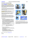
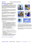
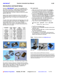
Faster Than Fast ® Excitron Au Controllercoder User Manual v4.30 Introduction and Quick Setup C o n o o d Excitron‘s Faster Than Fast ® AAAuuu C Co on ntttrrro olllllleeerrrccco od deeerrrsss are fully integrated with our stepper motors to make your motion control simple and easy. We pack years of design and plenty of power into ultra small gold plated Au Controllercoders, loaded with innovative features. They contain all the electronics and power for thousands of motorized applications—and they run right out of the box by simply typing a "G‖. They all have standard RS232 (+-10v) for serial port communication to any computer and PLC. USB-RS232 serial port adaptors are available. Various size, power, and control functions give you the best selection for your project. Au57-40M . Mini Z-Lift with camera Our Au Controllercoder /motor configuration and part number system A is also simple—Au57-76M is the number for the A Auuu C C o n o o d Co on ntttrrro olllllleeerrrccco od deeerrr assembled with our SM57-76M stepper motor. Stepper motors rotate one small step at a time, and are the best choice, because both position and speed can be precisely controlled, unlike any other type of motor. Our motors can run continuously for 30 years. Our experts are happy to assist you in selecting the best Au Controllercoder, stepper motor, and accessories for your project. We also offer linear slides, belt sliders, actuators, rotary tables, X-Y tables, XYZ machines, and heavy duty 3-axis milling machines. Visit our website for all documents, prices, and online purchasing. 10‖ Rotary Table MRT10-86-118-450 AuG86-118-5 For a quick start: Make sure the AC-DC power supply is off or unplugged. Connect the power supply/RS232 connector, which is a small 2x4 housing, to the Au Controllercoder. Note the polarizing post must be inserted into the open slot in the motor cover. If you have a USB-RS232 adapter, connect your USB cable between your computer and the Au Controllercoder RS232 DB9 connector. PC Software drivers must be installed. Turn on your power supply. The LED should be ON. Start Hyperterminal (or any equivalent program) with 57.6K baud, 8 bits, and no hardware handshaking. At power-up, the Au Controllercoder displays: Excitron Corp X> 12/01/12 v4.30 SM60-86 3.3‘ (1m) / second Wire Slider WS70-012 Reduction of Hazardous Substances (RoHS) Statement of Compliance Excitron is a product manufacturer and does not melt or produce any of the raw materials sold to our customers. Excitron only purchases ROHS parts, does not add or expose these materials to any of the hazardous substances (lead, mercury, cadmium, hexavalent chromium, polybrominated biphenyls, polybrominated diphenyl ether) listed within the EU RoHS Directive, except we use tinlead solder. As cited in statements from our vendors, the materials sold by Excitron do not exceed allowed levels of these substances because they are exempt, and therefore, the materials are compliant with the EU RoHS directive. Firmware versions v4.26 thru 4.30 are identical, except the cycle counting works well on v4.28 onward, and v4.30 has the encoder run-time modules removed. Au86-118 3 Type G to run the stepper motor (no longer have to type w). Type little i to see all Au Controllercoder information and the motion profile values. Change direction (C or W), Vsps, or number of steps N, type G, and see the difference. Type ? to display a brief command help list. The Au Controllercoder is in Command Mode, and will respond to any serial command. Input Profile, Motion Profile, and Driver Modes create additional and standalone functionality. Enjoy! Feel free to contact us at [email protected]. @ Excitron Corporation Superior, CO USA [email protected] www.excitron.com 1 of 10 Faster Than Fast ® Excitron Au Controllercoder User Manual v4.30 Key Features This document applies to all Excitron Au Controllercoders. See the individual motor Au Controllercoder data sheets for additional details about connector pins. The Au Controllercoder performs all calculations and intelligence to automatically step the motor. It also contains powerful motor drivers. No additional electronic device is needed to control and drive a stepper motor. You have the freedom to enter simple motion parameters to create ingenious stepper motor motion profiles. Serial communications and control use ASCII (alphanumeric) characters, thus no programming is required; all you need is a basic serial interface program like Hyperterminal. Your biggest goal is stepping your motor from point A to point B quickly and accurately. An Excitron Au Controllercoder allows you to attain this goal with truly simple commands for friendly use, yet versatile and powerful enough to control a sophisticated robotic automatic assembly machine. You can quickly change motion parameters to achieve your goal. You may opt for higher torque and faster movement after finding that the temperature rise is satisfactory. Or you may desire to reduce mechanical noise by varying the acceleration, SPS, or torque. Most step motor documents state that bipolar motors produce more torque than unipolar motors--that is not true with our motors and Au Controllercoders. Our proprietary circuitry was first developed and patented in 1976. Improvements continue steadily to maximize motor and Au Controllercoder efficiency, which maximizes torque. Three modes of operation are available: Command, Motion Profile, Driver, and I Input Profile. Onboard optical Encoders are optional and available in the near future. A full set of parameters for stepping the motor is called a motion profile. Twenty-four motion profiles are stored and retained, even after power is removed. A motion profile consists of acceleration, stepping at a constant maximum SPS (steps per second), then deceleration to stop precisely at the number of steps you specified. Deceleration is identical to acceleration. A time delay before or after motion occurs gives you precise timing control. Some key parameters are acceleration, maximum SPS (steps per second), number of steps, direction, and torque control. The Au Controllercoder uses unique current limiting circuitry for high efficiency and performance. By adjusting the acceleration, top SPS, and other factors, you can minimize the time required for a particular motion. A full range of acceleration is provided for any application: dog slow to extremely fast. SPS can be changed on the fly while the motor is stepping. Various input devices, such as limit switches and potentiometers, may be connected to the TTL/CMOS +3.3 volt logic input pins. Two input pins accept analog 0-3.3v and converts it to a digital value. Au Controllercoders have one TTL/CMOS +3.3v output that you may use to control relays, LEDs, and equipment (proper interfacing is required). A single LED provides visual feedback that power is applied, and it also indicates motor steps or serial communications. @ Excitron Corporation Superior, CO USA One key unique feature is the extremely low supply power for the Au Controllercoder electronics. With a 24-v power supply, the Au Controllercoder only dissipates 0.025 watt, which is insignificant. All internal voltages are self-generated and thus require only a single voltage supply. Built-in temperature sensing on Au Controllercoders, safeguards the electronics and motor from thermal burn out, the limit is 170 degF. Many aspects and limitations in competitor‘s Au Controllercoders are obsolete. Excitron Au Controllercoders drives any size unipolar stepper motor, even our 110-180—a 25pound Super-size 42! The power supply voltage range for Au86 and Au110 large motors is 9 to 48V, while all other Au Controllercoders operate from 3.3v to 30v. Many options are available. All Au Controllercoders are upgradeable to new features in the future via firmware updates, thus protecting your investment. Custom firmware applications are also available; just ask the friendly Excitron technical staff. What’s New New CNC Mode--ability to read gcode files, store, view, and execute for easy automation for robots and CNC machines. Enhanced Master/Slave features--one master Excitron Au Controllercoder sends serial commands to other Excitron Au Controllercoders via our Simple Serial Bus. This saves you time, space, money, and complexity by eliminating external PCs, PLCs, and other expensive CNC controllers. See CNC Gcode section. Electronic damping on last step for 2 seconds or more, and is adjustable. Driver Mode is integrated with normal Command Mode so you can have access to all commands while accepting step/dir. Motor torque is increased 10% if half-stepping by powering the half-step at 1.4 times normal. Half-stepping is now superior to full-stepping. New Master Au Controllercoder mode, where one Excitron Au Controllercoder sends serial commands to other Excitron Au Controllercoders via our Simple Serial Bus. This saves you time, space, money, and complexity by eliminating external PCs, PLCs, and other expensive Au Controllercoders. Command ―H‖ allows automatically finding home position at power up. Command ―h‖ rotates motor shaft to zero position. . What’s Coming Wireless communication, Zigbee, and internet address 6LoPAN. Warning! Use caution when operating, severe injury can result from the motor rotating. Long wires act like antennas and may cause erratic dangerous motion. [email protected] www.excitron.com 2 of 10 Faster Than Fast ® Excitron Au Controllercoder User Manual v4.30 Setup, Configuration, and Power Excitron motor Au Controllercoders can operate standalone, or in various modes. The onboard UART serial port is RS232, which contains all the electronics for RS232 (+-6 volts), included with every Au Controllercoder is a DB9 female connector. All 7 digits must be entered. If you enter fewer digits, the command is left waiting for completion. All input values are validated to be within the range specified for each command. Any input value outside this range results in a ‗?‘ being displayed and the default or existing value being used. If you send extraneous alphanumeric characters, a ‗?‘ is displayed and no values change. The exception to this rule is that commas, spaces, carriage returns (Enter or CR), and line feeds (LF) are ignored. Serial input characters are not buffered. You will also need a DC switching regulated power supply, with sufficient amperage to drive your step motor. The power supply voltage range for Au86 and Au110 large motors is 9 to 28V, while all others operate from 3.3v to 28v. These and other accessories are available on our web site. See Au_Controllercoder_Pins drawing for interface pins. The power supply wires should be at least 20 AWG stranded, 18 AWG is best, and as short as possible, 4 to 12 inches. The amount of current into the motor is NOT the power supply current. A rough guideline is the power supply watts out to the motor equals the motor watts (watts = volts x amperes). You will need to budget at least twice the motor‘s watts. Power (in watts) is also defined as amperes x amperes x resistance. Excitron‘s Au Controllercoders can operate at 2 times the rated value for intermittent operation. If the power supply amperage is inadequate, the Au Controllercoder may pull the power supply voltage low enough to cause a reset of the Au Controllercoder. This is harmless to the Au Controllercoder, but stops your motion. If you operate in Motion Profile mode (described later), then the Au Controllercoder will begin anew at the first motion profile selected by the U command. A computer running Hyperterminal, RealTerm, or an equivalent serial port communications program is required. The serial port operates with 8 bits, no parity, 1 stop bit, and 57,600 baud (initial). Protocol is none, no hardware handshaking, and just ASCII alphanumerics. The Au Controllercoder will echo all characters received by default, therefore turn off Echo in your communication program. Once setup in various mode, the RS232 serial port is no longer needed. Each Au Controllercoder has an assignable Axis address, the default address is ‗X‘. Sending Commands to the Au Controllercoder The format of Au Controllercoder commands is simply send the single letter of the command. Important--capital and small letters are different. If user input is expected after the command is typed, the Au Controllercoder responds with '=', the existing value, a colon and a space. This existing value also shows the exact quantity of numbers to send. Then it waits until you send the required quantity of numbers. After all input is received, the Au Controllercoder will send a LF (line feed), CR (carriage return), Axis address, and a prompt ‗>‘. The ‗>‘ provides feedback to host computers that the command is complete. In other modes, the mode character is also sent. Do not type ―Enter‖ key after typing your command, type only the command and any characters as specified by the each command. Note that the ASCII numbers are fixed field format. This means the exact required quantity of alphanumerics must be typed. For example, to enter a step quantity of 188 steps, type: N (Au Controllercoder sends ―=0033000: ―) then 0000188 At power up, the Au Controllercoder is ready to accept serial commands. The command prompt is ‗X>‘. If you changed the Axis address, then that address appears. The information command is i, which displays all Au Controllercoder parameters and the selected motion profile. Commands may be typed in any sequence and the Au Controllercoder remembers your last typed values. See the Motion Profile section for how to save your values permanently with the U command. Changing Au Controllercoder Configuration The little c command accesses commands for changing the Au Controllercoder operation and features. New prompt is ―send ~‖, you must type a ―~‖ to continue. c submenu Commands are: A=X: Axis address ABCDEXYZ for CNC Simple Serial Bus. b=57.6K: select baud: 1=4.8K, 2=9.6K, 3=19.2K, 4=38.4K, 5=57.6K (default), 6=115,200, 7=230.4K. Type just one digit of the baud and immediately the baud is changed. d driver mode, see Driver Mode section for details. E=060: Encoder value range; 000 = disable e=1: echo received serial characters if =1.. h=0: home enable: 0 = disable, 1 = enable, runs at reset/power. M=1: Master if = 1, slave if = 0. Master always sends responses, slaves only send response if ^ (up caret) command is issued once after power-up. Underscore _ command turns off slave responses. P=+-0000836: change Motor/Encoder Position o=0: output a 5 usec pulse on Out5 for each motor step v=1: view each motor step pulses while the motor is stepping: 0 = off, 1 = on. If on, each motor step CW is an m, CCW is an M. Use for external monitoring of position and speed real-time. 57.6k Baud limits top speed to 5,500 sps; 115k baud limits to 10K; 230k baud limits to 20K. Character overrun occurs at higher sps, so use wisely. z=018 sets an internal amperage value, normal is 018. q quit and return to main command menu. Simple Serial Bus connects multiple Au Controllercoders with one host/PC serial port, or no external computer at all. The simple protocol is: STX-address byte-data bytes-ETX. STX is ctrl-B and ETX is ctrl-C. A slave responds to commands only if a STX and matching address is received. You wire the host‘s transmit to the Receive of one Au Controllercoder, its Transmit to the next Au Controllercoder Receive, and so on, and the last Au Controllercoder Transmit is wired to the Receive of the host. See the Excitron_CNC_Gcode_Robot_System.pdf. Setting Motion Parameters @ Excitron Corporation Superior, CO USA [email protected] www.excitron.com 3 of 10 Faster Than Fast ® Excitron Au Controllercoder User Manual All motor parameters required for sophisticated motion control of your motor are described here in alphabetical order. You type only the characters shown in bold. The Au Controllercoder displays the equals sign, the existing value (from 1 to 7 numbers), colon and a space (most commands). st A=120: nnn Acceleration (1 Vsps), A=060 is allowed. C Clockwise motor direction, as viewed from the motor face. D=1: n Down/up sps before running using IN3 analog pin: 0=no, 1=enable, IN4 input pin sets direction—low is CW, high is CCW. This D is not the slow-down D while running. M=0: n Micro stepping, full step is 0 and half step is 1. N=0012000: nnnnnnn Number of steps. r=006: nn repeat quantity, from 001 to 255, if > 100, then r = 10 x r. The remaining repeat value is output after each motion, except the last. t=+-00800: nnnnn time delay either before (+) or after (-) the motor motion. Input +- or -, then 5 numbers representing milliseconds, e.g., t=+00500 defines a 500 millisecond time delay after the motor motion. v4.30 V=04600: nnnnn Velocity--maximum SPS. Note that the step quantity and acceleration values may define a motion such that the maximum SPS will not be achieved. Counter-clockwise motor direction. W ) ( Rotate 1 step clockwise. Rotate 1 step counter-clockwise. f,F,m 3 input values that set a flat speed portion at the beginning, rear, or both of the speed profile. ^ up-caret character—sending to a slave enables all serial port responses. _ Underscore character—sending to a slave disables all of its serial port output except > for completion. The new Damping delay gives you automatic holding at the end of motor running. You set this value on c submenu with command D. Each unit gives you about .56 second delay: minimum is 02 and maximum is 30. Setting Motor Stepping Torque Motor torque is directly proportional to motor current, with some non-linearity. Torque is defined as Force x Distance, and is usually measured in oz-in (ounce-inches). The Au Controllercoder uses unique current limiting circuitry for high efficiency and performance for the user. Step motor current (amps) must be limited, or excessive heat and amperage can destroy motors and Au Controllercoders. Most step motors are rated for 2 to 5 volts; so Excitron‘s current limiting allows them to be connected to a higher voltage (12 and 24 volt being most popular) power supply. You control precisely the amount of torque in the motor with one simple command: damage the Au Controllercoder. You are responsible for any damage to the Au Controllercoder or motor. If the temperature limit is reached, the motor ceases running. Then the LED blinks once per second, and a ―s=x Hi temp‖ message is sent from the serial port, where the ―s=x‖ part of the message is the address of the unit sending this message. No operations occur until an @ reset character is received or power is cycled. Note that this terminates Motion Profile Mode, and the Au Controllercoder is then in serial Command Mode. T=050: nnn You step the motor with the G, g, and S commands: sets the internal percentage of full motor torque. A low value for T, such as 020, produces low torque. Typically use T=040 to 080. Higher values increase torque. Start at low values for T and increase the value until your motion is satisfactory. Do not increase T without adjusting V first. And do not increase T to make the motor run faster. At higher speeds the T is not effective-it is only effective as the motor spins up and during deceleration. After determining the suitable values, adjust T up or down for best performance vs. heat buildup. The Au Controllercoder measures power supply voltage at startup, and automatically adjusts the amperage. You do not need to adjust T if swapping power supplies, the voltage measurement is automatic. After a certain SPS, the Au Controllercoder determines that current limiting is no longer needed, and the motor is ―fully on‖. Torque is then limited by the motor‘s reluctance. The power supply voltage is the largest factor for torque. Motor current is rated based on the amount of current that causes the motor to reach 85 degC in 10 minutes. If mounted to a relatively large metal plate to dissipate the heat, this current rating will increase significantly. For intermittent operation, which is most stepper motor applications, the motor may be over-driven up to 2 times its rated power, depending on many factors. Warning—stepper motors require amps of current, and overheating and damage can quickly occur. Start with low T values, then gradually increase while monitoring temperature via the i display. Maximum operating temperature is hot to the touch, and may burn you. Selecting higher torque than allowed may @ Excitron Corporation Superior, CO USA Stepping the Motor G g S ) ( Go step the motor for the specified N number of steps. Reciprocating motion--same as G, and at its completion, the motor reverses direction and performs exactly the same motion profile. Step the motor continuously. This command ignores the step number entered. Only a motor stop command O or o will stop the motor. run one motor step CW, any unsaved changes are discarded. run one motor step CCW. After you type G, g, or S, you can send U, D, O, or o: U Speed up the motor on-the-fly. The SPS increment is determined by the V value. D Slow down the motor on-the-fly. The SPS decrement is determined by the V value. O Starts deceleration gracefully and the motor slows down and stops.. o Motor stepping is stopped immediately. The motor‘s inertia may cause erratic motion for a few steps. The motor will stop if sufficient D‘s occur. You may set the Vsps prior to running by using IN3 analog input pin, which is enabled with the D command (this D is not the slow down D): D=0: 1 0 disables, 1 enables Vsps set by In3. [email protected] www.excitron.com 4 of 10 Faster Than Fast ® Excitron Au Controllercoder User Manual V4.22-4.26 does not allow changing speed while running. The adjacent input pin IN4 sets the direction—low is CW, high is CCW. The original SPS value in the Motion Profile remains unchanged. quantity. To step the motor again, with the same parameters except CCW (counter clockwise), type: W G After running, the motor coils are energized to electronically dampen the motor shaft for ultimate step response. You may immediately start another run during this damping. You set the time for damping with the c submenu D command. Each unit gives you about .56 second delay. This feature is especially useful for vertical drives. Note that the other commands do not have to be re-entered. The Au Controllercoder temporarily stores the last values of all parameters and commands. Save permanently by using the U command, see Motion Profiles section. Be aware that the motor and Au Controllercoder will heat up faster while running at slower speeds. At SPS over 3,000, depending on power supply voltage, the motor‘s inductance, the motor self-limits the power, and should run cooler. A temperatures over 50 degree C may feel hot to human touch, but that is ok for motor and Au Controllercoder operation (up to the high temperature limit). Braking When the motor is not stepping, motor current (amps) may be applied to create a braking (holding) torque. WARNING--high temperatures may occur rapidly with high brake values over 110. Values from 040 to 060 produce little braking, and values between 080 and 100 are typical. Always increase braking values slowly and check heat. If you do not need braking torque, specify zero braking current by typing: B=000: nnn Braking (holding) current limiting parameter. Range of values is 000 and 040 to 100. Power saved by minimizing braking results in greater torque available for motor stepping. Higher current results in higher temperatures. B=000 also reduces the Au Controllercoder power consumption. Any reset makes B=000 for Profile #01 only during Command mode, the saved B value is unchanged for all other modes. P 01 or v restores your B value, be careful. Home Command You can enable the Au Controllercoder to auto-home at startup by setting h (under the little c menu) to 1: c>h=0: 1 0 = disable, 1 = enable When enabled, Motion Profiles 04 and 05 are run to completion. You have complete control of the values in these 2 profiles, including which direction to rotate and your input sensor pin. Suggest setting Profile 05 for backing up a small amount of steps at a lower speed, to increase homing accuracy. The value of h is displayed with the i command, on the Encoder line. You can home at any time by sending H, which runs Motion Profiles 04 and 05. Note that auto-home also runs if Motion Profile Mode is enabled. Rotate the motor shaft to position zero, if Encoder enabled: h (this is not the c>h command) Command Examples and Notes Suppose you wish to rotate the motor for 10,244 steps clockwise, half stepping, and a maximum SPS value of 1,800. Send: N=0000080: 0010244 C M=0: 1 V=04200: 01800 G Note that you do not type ‗>‘, ‗=‘ nor ―enter‖ with any command, the Au Controllercoder provides it. The ‗>‘ prompt is not shown here for clarity .The order of the N, C, M, and V commands is not important, but the G command is, since it starts motor motion. The M, N and V commands must receive their required exact digit @ Excitron Corporation Superior, CO USA v4.30 Acceleration, maximum SPS, torque, and other parameters can be optimized for your application. An acceleration value of 0120 is a good starting point for half-stepping. The Au Controllercoder automatically decreases acceleration as speed increases. This optimally matches the stepper motor‘s output torque curve, better than a linear speed curve. Many interesting combinations exist to create the motion you need for sophisticated control of automatic assembly machines or for motorized products. The time command t, can be coupled with various input mode commands to produce intelligence and control for almost any application. All stepper motors have a natural resonant frequency around 200 to 1,200 SPS. If stepped at constant SPS in this speed range, the motor may vibrate and lose steps. This condition is worse at higher torque settings. It is best to accelerate through this range. Lower T values reduce resonance and miss-stepping. You should always run using half-step (M=1), which helps a great deal. When changing from half to full stepping, the Au Controllercoder may shift a half step to always be on a full step. Power-ON Reset The Au Controllercoder has sophisticated power-on reset and brownout voltage protection circuitry. This protects from power supply glitches, and increases the Au Controllercoder’s robustness and integrity. The Au Controllercoder waits a few seconds for your power supply to stabilize before allowing any motor motion. The RESET pin is normally high. To reset the Au Controllercoder, send a logic low-level control to this pin, and release. After any reset, Brake is 000 for Profile #01 in Command Mode only--the saved eeprom value is unchanged. This protects against unplanned heat build-up. The first motor step after powerup or reset is always the same step, and 1-3 steps may be needed to sync the Au Controllercoder with the motor‘s last rotor position. The high value filter capacitors in the power supply provide considerable power supply voltage spike attenuation, and a 1-4 second hold-up time. When switching off, always wait briefly before unplugging. Software Reset and @ Commands Software reset by sending @, which restarts the Au Controllercoder as if a power-on reset occurred. Use this command to terminate Motion Profile and Driver Modes, and run [email protected] www.excitron.com 5 of 10 Faster Than Fast ® Excitron Au Controllercoder User Manual v4.30 serial commands. Do not use this reset command more than 100,000 times due to eeprom write limit. Driver and Input Profile Modes restrict some pins as general input. For repeat and/or reciprocal motions, an input triggers only 1 motion, not multiple motions. Other special @ commands are: I (Input) Profile Mode @@{ followed by any character (besides STX)--sends Axis address. @@@ (3 @‘s in a row)--clears Home & Input Profile mode I to 00. Input/Output Pins and Modes You can create very interesting and versatile control of stepper motions by using the input pins and their pinmodes. Some control features are: stop and go control, logic only; wait for two inputs to occur; sequence external events, extended time delays; or other ingenious reasons. All pins are TTL/CMOS compatible (0 to +3.3v) and are also +5 volt tolerant. They have Schmidt triggers for noise immunity and +-30kV static protection. You read your Au Controllercoder pin values and the Input Profile Modes with the J command: IPM: -06 -09 -12 +15 +18 +21 Pin: In2 In3 In4 In6 In7 In8 Out5 1018 252 1 1 1 1 0 The In# is the 2x5 I/O connector pin number, and the J command also shows the matching Input Profile Mode number, useful for the next section. Each input pin is normally high (+3.3v) and can be connected to switches (optical, mechanical, etc.) or to monitor signals from other electronic devices. The correct connection is for one terminal of the switch/control connected to ground, and the other terminal connected to the input pin. Input pins In4-In8 are digital only, and have an 8.2K (+- 5%) pull-up resistor to +3.3 volts. Input pins In2 is digital or analog, depending on the pinmodes, and have a pull-up resistor of 35K (+- 10%). The output pin Out5 is normally low (0 volts) and can source 1 ma to +3.3 volts, or sink 10 ma. The +3.3 volt pin 10 can provide 3ma for external circiuitry. Do not exceed these current levels, or the Au Controllercoder may reset. Analog input In2 measure voltage levels, such as potentiometers, with 10-bit resolution. The J display is the digital representation of the analog value, with a full range from 0000 (zero) to 1023 (+3.3V) ( is 8 bit when used for setting Vsps). If used for digital switch inputs, then any value near 0000 is a digital low while any value close to 1024 is a high. Use a 10K or 25K ohm potentiometer. An internal analog input may exist as Sw2. You specify the pin number and the pin mode with the p command (little p). Two inputs are expected, for example: st nd p=3: 5 mode=01: 13 1 value is the connector pin number. 2 value is the mode, ranging from 00 to 31. A pin value of 0 will ignore any pin and its mode in that Motion Profile. Valid Pin Modes are: 00 – wait until pin is low, then step 01 – wait until pin is high, then step 09 – at power-up, count pin CTR, using Profile 01 repeat value 12 – step until pin goes high, then stop smoothly 13 – step until pin goes low, then stop smoothly 14 -- step until analog pin In2 > ADC value, then stop smoothly 15 -- step until analog pin In2 < ADC value, then stop smoothly 28 – output pin is high at start, low after motion profile 29 – output pin is low at start, high after motion profile @ Excitron Corporation Superior, CO USA The I command enables the input pins to randomly run a set of 3 motion profiles. This gives you great standalone operation, and can be used in all other modes. For example, 6 push buttons can select any of 6 positions for .01, .10, .50, 1.00, 2.00, and 5.00 inches of travel. The I values are set independently of each other, and these are the allowable values: I=+06 or +86 runs Profiles 06, 07, & 08 I=+09 runs Profiles 09, 10, & 11 I=+12 runs Profiles 12, 13, & 14 I=+15 runs Profiles 15, 16, & 17 I=+18 runs Profiles 18, 19, & 20 I=+21 runs Profiles 21, 22, & 23 (In2) (In3) (In4) (In6) (In7) (In8) When you type I, the Controller sends all 6 current values, and waits for you to type + (enable) or – (disable) followed by one of the valid numbers, and your new value is auto-saved. The new analog I Profile Mode for In2 (In3 analog was removed as of v4.22) will trigger their 3 profiles when the analog pin value is lower than the k ADC value you specify, in the Motion Profile, using the k command. Example: I =+86 and k value = 0910. Profiles 06, 07, & 08 run when the analog value on In2 pin is lower than 0910 (2.9 volts). Input pins are active low. Once triggered, the 3 profiles run to completion, even if the input pin is raised high, so use caution. To run only 1 profile when the input goes low, set the remaining 2 profiles with N=0000000 and t=00000 so that they are ignored. You may also use an input pin and mode inside the Motion Profile. Driver Mode or external encoder disables the corresponding Input Profile Modes. Sending 3 @‘s in a row (@@@) clears I to 00. See page 10 for more details. Motion Profiles The Au Controllercoder stores all motor stepping parameters for each of the 24 motion profiles. You can view and edit these profiles individually, and then set them to automatically execute from memory upon power-up. The motion profiles are stored in EE memory, and thus retain their values when power is off. The major purpose of motion profiles is to allow a standard programmed Au Controllercoder to operate as a standalone unit, not needing a PC or external Au Controllercoder. Once set up, only a power supply is needed. With the Q command, you specify any of the 24 profiles as the starting profile, and a subsequent profile as the last one, for example, profiles #05 through #12. The Au Controllercoder will sequentially run these motion profiles, and automatically repeat after the last one is completed. You can easily modify existing motion profiles to fit your own application by entering values for acceleration, SPS, etc. The Au Controllercoder provides for a broad range of applications. All you do is change the profiles. You can change motion profiles for designing, trouble-shooting, demonstrating, or marketing purposes. For example, most mechanisms operate at blinding fast speed—the motion profiles can be altered to slow down an interesting movement so that fine details can be observed. Since most applications only use less than 5 profiles, you can create an entire second range of motion [email protected] www.excitron.com 6 of 10 Faster Than Fast ® Excitron Au Controllercoder User Manual profiles that operate at slow speed. You can even offer this feature to your customers. The commands for retrieving, displaying, and saving motion profiles are: P, Q, U, and v (little v). For each of these commands, simply type the letter of the command. The Au Controllercoder responds with a ‗=‘, then you type the required numbers. If you issue a P, Q, or v command, changes to current parameters are lost, unless you save them first by using the U command. P=nn Display the motion profile specified by nn. Q=nn yy Quit command mode and start motion profile (standalone) mode. Thereafter, at power up or a reset, the Au Controllercoder will automatically run the motion profiles you specify with the nn and yy numbers. U=08: nn Update and save the current motor parameters to the motion profile specified by nn. Example: U=08:03 will store the current values in 08 to motion profile 03. v View all 24 motion profiles. The Au Controllercoder displays a header line, followed by 24 data lines. Special note for the U command: it stores the last G, g, or S value executed, into the motion profile you specify. This is the only command to store the G, g, or S value. You can enable the Au Controllercoder to auto-home at startup by setting h (under the little c menu) to 1, see Home Command section. With a few simple command settings, you can create very interesting motion profiles. For instance, if P #01 is CCW and set for mode #13, P #02 is CW and set for mode #12, and you have a switch connected to an input pin, then after you start motion profile mode with the Q command, the switch position determines direction of rotation! You stop the Au Controllercoder from executing motion profiles by typing the reset command @. The Au Controllercoder will execute motion profiles again if you issue the Q command. In the normal command mode, you can change any motion profile and then save it, overwriting any existing motion profile. The motor stepping parameters may also be loaded by sending an ASCII text file. The format of this file may be any of 3 formats: csv (comma separated values), space separated values, or nothing between values. An example of a csv format, created from MS Excel or Notepad, is: A0200,V04400,B000,N0080000,U12 Note that the order is not important, except the U12 command is last, which saves the input values to Profile number 12. You may also have CR and/or LF after each input command. If you send multiple lines, you must insert a 300-millisecond delay after each line to allow the Au Controllercoder to finish writing its internal values. The Au Controllercoder does not buffer input commands. Windows Notepad or similar text editors can be used to capture information via cut and paste, or to set parameters. Note that eeprom writes require 10ms per character to save data in the Au Controllercoder. When running motion profiles, the Au Controllercoder outputs the letter P, the profile number, and a space, followed by the repeat number(s) (counting down) and a space, if echo is on. The life expectancy of the EE memory is 100,000 write commands (Q or U). Do not exceed this number. Driver Mode You set Driver Mode for step/dir signals operation by typing little c then little d=1, and it is saved immediately, and the prompt changes @ Excitron Corporation Superior, CO USA v4.30 to X d>. Setup your favorite CNC program, which send steps and direction pulses from a PC LPT1 parallel port, or other device. The Au Controllercoder steps the motor using 2 external input signals Step and Direction: STEP DIR negative or positive going pulse, > 5 usec, this is IN7 0 is CW, logic 1 is CCW, this is IN8 Driver Mode is now integrated with Command serial mode so that you can also run all serial commands, such as i or G. The only precaution is if the motor is running using step/dir, do not run G or any other run command until Driver steps are complete. The Au Controllercoder is CNC-ready, and runs with almost any CNC PC or PLC program and +3.3 or +5 volt logic. An enable signal is not needed because the Au Controllercoder will automatically stop when the STEP pulses cease. The Au Controllercoder serial port can be used for stepping, especially in CNC mode. Do not wire +12 or +24v directly to the input pins. In Driver Mode, internal Torque (amperage), temperature, Full/half step, Brake, and Encoder controls are maintained automatically by the Au Controllercoder, using the current Motion Profile. Use caution if you change Profiles. Switches, and Input Profile activations give you easy jogging or other semi-automatic positioning. Since Driver Mode uses two input pins for step/direction, the corresponding Input Profile Modes are disabled. The improved Driver Mode (step/dir) automatically processes active high or low pulses, and with no time restrictions. Since it is possible to run the motor using an input pin or RS232 serial characters, do not send CNC step pulses while the motor is already stepping, and vice versa, or they will be lost. Help, Hints and Tips ? Displays the simple command help. The Excitron motors and Au Controllercoders definitely have the torque range specified, and generally, torque decreases as speed increases. Small burrs, chips, non-flatness, or dents on your moving parts can result in the motor stalling. The faster you step, the worse the effect of the small burr. Also be aware that even small machine screws can exert a thousand pounds of force, bend heavy steel parts, and thus bind up moving parts. Tightening a small timing belt can bend steel motor shafts easily, due to the leverage action. Stepper motors run faster and stronger with direct shaft attachment. Best is to slide our motor shaft into a precision bored hole in your part, and clamp using a C collar clamp. Note that if you‘re bored hole is off even by .003‖, your top speed will be limited. Non-rigid ―rubber‖ couplers introduce vibration and phase lags, which can cause motor stalling. Best is to shock mount the motor, not the drive parts. If your motor just hums without stepping, check your V, and T values. DO NOT increase T while trying to get the motor to spin faster—see other notes about T. If your Au Controllercoder has manual push buttons, push one to see correct rotation. Once you verify correct running, then increase V to suit your purpose. Use multiple Motion Profiles for added control. For instance, with r = 250 (repeat = 2,500) set in three consecutive Motion Profiles, then when you run all 3 Profiles, the repeat quantity is 7,500. For longer time delays, use multiple Motion Profiles. [email protected] www.excitron.com 7 of 10 Faster Than Fast ® Excitron Au Controllercoder User Manual If 1, 2, or 3 Motion Profiles suit your operation without autorepeating, then use I Input Profile Mode, which trigger once each time that particular input pin goes low. And this works well with up to 6 inputs. If you need 4 or more profiles, and automatically repeating forever is desired, then use Motion Profile Q Mode. In either mode, once started, an input pin can control motion. An example is I=+21, and Profile #22 has p=8 mode=00. Pushing a switch attached to In8 triggers Profiles #21-23, but motion stops at Profile #22 because p=8 mode=00. Pushing your switch again triggers Profile #22 then #23. New technology! Excitron Au Controllercoder motors can now execute Gcode directly from its own memory, thus eliminating an external PC, PLC, or controller. Saves you money, time, and a lot of space. 8 axis are standard. Excitron provides a mini-operating system for easy motor motion, while maintaining the Motion Profiles command system. It gives you enough power to sequence over 3,600 motions for 86 and 110 series, 120 motions in all other controllers. The Excitron 24 Motion Profiles remains as a robust motion sequence and control system. Gcode files are read into RAM memory, and then can be stored into flash for permanent storage. To use the Gcode/Robot system, type n and ~ from the main menu. CNC Comands are: i l r The input gcode file is a simple text file with general gcode structure. Distance is in motor half-steps, not inches, and is incremental. + is CW, - is CCW, while neither is assumed as CW. Feed rate is in half-steps/second, and is sent to all 8 possible Axis. Line numbers and comments (;) are ignored, spaces are allowed. Example of an input file: M06 is a general pause or tool change, restart after ~. You can download your gcode text files into the Au Controller coder motors, then view, save, retrieve, and execute gcode files. Unique feature: each axis has its own distance and feedrate (speed), unlike all other gcode controllers. Now you can have total control for multi-axis robots and CNC machines. One Au Controller operates as a Master, and the other Au Controllers in your system are slaves. You set Master with the c>M command. Each Au Controller has its own Axis address, and choices are A, B, C, D, E, X, Y, Z. Set the Axis address using the c>A command. G Save the file in RAM to flash stoarage, type ~ to confirm. view the file in RAM, line numbers are added. Erase all flash files, must type ~ twice to be sure. help list of commands, only 86 and 110 Controllers. F1200 ;sent to all 8 axis Z-2000 X40000 F2100 Y2000 ;feed rate sent only to Y Axis Z2000 M30 ;end of program, this is mandatory Gcode/Robotics Operating System d D S v ! ? v4.30 directory of all files in flash storage. direction reversal, enter an Axis letter, then 0 for none, 1=reverse. Changes are stored immediately, use i to view. Go execute the file in RAM. Commands are sent to the slave Excitron controllers. G command sends the underscore command so that slaves do not send any characters, except for the > completion. information. load a file in flash to the RAM. read an external file into RAM memory. Enter a filename after typing r. Filename must be at least 2 characters, letters and numbers and some syhmbols only. First letter of file name must be a letter. Excitron uses this Gcode to machine our own parts. One Au86 motor can store every part we make, and many more. A Simple Serial Bus cable is required. Since the cable is RS232, you can run the cable up to 40 feet total length. Position step counter Details The Au Controllercoder maintains and validates Position step counter, at each motor step, up to +-9999999 steps. The Shaft value is also constantly updated real time, stored in volatile memory, but is only a calculated value, not measured. The Position and Shaft values are available with the i command. You enable the sending of the Position value after each motion by setting the E value to be non-zero, this command is on the c submenu, and any changes are immediately saved in eeprom memory. Example: G P=+00000912 023 Main menu commands associated with the Optical Encoder is: X Position value can be set, +- 7 digits. The little “c” submenu encoder commands are: E enable if non-zero, else is not displayed after each motion. Any motion may be harmful to people or your mechanism, so use care in all situations. Additional Command Details The i command provides important information: Excitron Corp 12/01/12 v4.30 Au86-118 3 firmware date/version, Au #, memory number baud echo degC +Vs Axis:direction 57.6K 1 021 24 A:0 B:0 C:0 D:0 E:0 X:0 Y:0 Z:0 Au Controllercoder values Revs Encdr Motor Position Shaft v Play home out Damp 060 00200 +0000000 012 1 000 0 0 08 Position and Encoder values Axis:direction, appear only if Master P# D M G Acc Brk Number Vsps Trq% msec rep pinmode f Fnum msps DU e In2 01 C 0 g 120 000 0004800 03600 012 –01000 004 3 01 0 0100 0125 1 0 0344 @ Excitron Corporation Superior, CO USA [email protected] current profile values www.excitron.com 8 of 10 Faster Than Fast ® Excitron Au Controllercoder User Manual v4.30 rd The 2nd & 3 lines show hardware values: baud is serial port bits/sec; echo =0 (off) or 1 (on); All Au Controllercoders measure temperature and voltage: degC= degreeC of the Au Controllercodermotor, Vs = power supply voltage. Next 2 lines show: Revs (temporarily disabled), Encdr = Position displayenable. Motor = motor full steps/rev and is fixed for each motor. Position = motor step count, + (CW) or – (CCW), 9999999 max. Shaft = physical half-step position of the motor shaft, relative to your zero location. v = view motor steps real-time on serial port. Play is temp. disabled. out = putput pulse each motor step, Damp is time delay value, 2 second minimum, each unit is about .5 seconds. The last two lines, which are also displayed after i, P or v commands, are described below. Note that this display also defines the quantity of input numbers for each parameter. The following table describes each of the column headings, and defines the minimum, maximum, or allowable values for the parameters. Heading Cmd Description, these values apply to the motion profile, and are all saved when power is off with the U command P# P Profile number, 01 to 24 D C or W direction of rotation, C (clockwise) or W (counter clockwise) M M Micro stepping, 0 (full) or 1 (half) G G,g,or S Go—run this motion—G (single), g (reciprocal), S (continuous) Acc A Acceleration, fixed at 120 or 060 steps/second as first step rate, acceleration, slightly decreases as speed increases. Brk B Brake, 000 to 120—use care with braking values—132 is full on! Number N Number of steps, 0000000 to 9999999 (for larger values, use S command for continuous stepping) Vsps V Velocity maximum steps per second, 00114 to 18,000, max depends on motor size Trq% T Torque percent of full rating, 020 to 150—use with care, changing T changes the amperage! msec t time delay in milliseconds, before (+) or after (-) the motion profile, 00000 to 65000 rep r repeat quantity, 01 to 255, if >100, qty = 10 x r. While running, the remaining number is output. pinmode p Input pin to control this motion (0 means to ignore), then enter a mode number, 00-31. f f run at a flat sps using msps, 0 = ignore, 1 = at start, 2 = at end, 3 = both. (for end, Acc must be < msps) Fnum F number of steps to run at msps, minimum is 0002, according to ―f‖. Add to N to get total steps. msps m minimum sps for running at start or end, minimum is 0114, msps must be < Vsps, according to ―f‖. DU D DU (down/up) change speed by using analog input pin In3, 0 = ignore, 1 = enable, In4 SPS_dir sets direction. e e enable (=1) or disable (=0) auto-stopping the motor if detected by the Encoder. In2 k Analog input value 0 to 1000, for pin/modes and for I Profile Modes analog compare +86. Remember to type ? for built-in command help. Options USB-RS232 external adapters (1-port, 2-port, 4-port) for USB serial communications. Firmware modifications--to reduce or eliminate your external electronics, such as PLCs or computers. Disclaimer—all values and statements contained herein are subject to change without written notice. No products manufactured by Excitron may be used for life support equipment, full notice on our website. Use extreme caution when operating--severe injury or death can occur because motors move and rotate. @ Excitron Corporation Superior, CO USA [email protected] www.excitron.com 9 of 10 Faster Than Fast ® Excitron Au Controllercoder User Manual v4.30 Examples of using I Profile Modes with pin/modes You can achieve remarkable and interesting motion by combining I Profile Modes with a pin/modes. The following example is how we setup the Motion Profiles for use with our Switchbox. It explains the simple setup, and to offer further help about the differences between I Profile Modes and Input pin/modes. Please read those sections. The following view is obtained from Au86-118 by sending the i and v commands, then copy/paste here: X>i Excitron Corp 12/01/12 v4.30 Au86-118 3 baud echo degC +Vs Axis:direction 57.6K 1 021 24 A:0 B:0 C:0 D:0 E:0 X:0 Y:0 Z:0 Revs Encdr Motor Position Shaft v Play home out Damp 060 00200 +0000000 012 1 000 0 0 08 P# D M G Acc Brk Number Vsps Trq% msec rep pinmode f Fnum msps DU e In2 01 W 1 G 120 000 0000800 02000 060 -00000 001 0 00 0 0100 0100 1 0 0255 X>v P# D 01 C 02 C 03 C 04 W 05 C M 1 1 1 1 1 G G G G G G Acc 120 120 120 120 120 Brk 000 000 000 000 000 Number 0000400 0000400 0001600 0003000 0000020 Vsps 06000 02000 03000 01000 00600 Trq 060 080 090 080 080 msec -00200 -00000 +00200 -00030 -00200 rep pinmode f Fnum msps DU e In2 001 0 00 0 0100 0100 0 0 0420 Driver Mode values 001 0 00 0 0100 0100 0 0 0420 001 0 00 0 0002 0250 0 0 0420 001 0 00 0 0003 0045 0 0 0420 Home values 001 0 00 1 0002 0100 0 0 0420 Home values 06 07 08 09 10 11 1 1 1 1 1 1 G G G G G G 120 120 120 120 120 120 000 000 000 000 000 000 9999999 0000000 0000000 9999999 0000000 0000000 06000 03000 03000 01800 03000 03000 080 080 080 080 080 080 -00200 -00000 -00000 -00000 -00000 -00000 001 001 001 001 001 001 2 0 0 3 0 0 12 00 00 12 00 00 12 C 1 G 120 000 9999999 02000 060 +00200 001 13 W 1 G 120 000 0000000 03000 050 -00000 001 14 W 1 G 120 000 0000000 03000 052 -00000 001 4 0 0 12 0 0002 0100 00 0 0004 0130 00 0 0004 0130 1 0 0420 I=12 IN4 0 0 0300 0 0 0560 15 W 1 G 120 000 9999999 04000 080 -00050 001 16 W 1 G 120 000 0000000 03000 080 -00000 001 17 W 1 G 120 000 0000000 03000 080 -00000 001 6 0 0 12 0 0002 0100 00 0 0004 0050 00 0 0004 0050 1 0 0420 I=15 IN6 1 0 0420 1 0 0420 18 C 1 G 120 000 9999999 06000 008 -00400 001 19 W 1 G 120 000 0000000 03000 008 -00000 001 20 W 1 G 120 000 0000000 03000 008 -00000 001 7 0 0 12 0 0002 0100 00 0 0004 0050 00 0 0004 0050 1 0 0420 I=18 IN7 1 0 0420 1 0 0420 21 W 1 G 120 000 0000800 02400 070 +00700 001 22 W 1 G 120 000 0000000 02400 075 -00000 001 23 C 1 G 120 000 0000800 02400 060 +00700 001 8 0 0 12 0 0002 0100 00 0 0002 0100 00 0 0002 0100 0 0 0420 I=21 IN8 0 0 0420 0 0 0420 24 C 1 G 120 000 0000004 00200 082 -00000 001 0 00 0 0002 0100 0 0 0420 C C C W W W 0 0 0 0 0 0 0002 0002 0002 0002 0004 0004 0100 0100 0100 0100 0050 0050 0 1 1 0 1 1 0 0 0 0 0 0 0420 I=06 IN2 0420 0420 0420 I=09 IN3 0420 0420 Extra line spacing is shown here for clarity. These Motion Profiles and pin numbers are the same for all Au Controllercoders. The far right column shows the special Motion Profile functions. The AuSW4-2 Switchbox has a pot for analog input IN2 and a pot for IN3. The IN3 pot sets the Vsps speed if D=1, where upon IN4 is used for direction. This speed setting works on any Motion Profile that has D=1. Notice that in Profile 12, the same input pin IN4 is set with mode 12, which is ―run until this pin goes high‖) and this is used to stop motion. Why does this work? First, a switch is wired to IN4. Flipping the IN4 switch low (ON) triggers the 3 motion profiles, then when you flip the switch to high (OFF), the motor gracefully stops because of pin 4 mode 12. Same pin, but two different functions. Similarly for the other input pins. If you want to run a fixed distance, then make N = your step quantity and pinmode = 0 00, then when you flip the switch up and down, the motor runs the number of steps you specified. Errata and notes V4.30 Corrected manual for command X (was P) for editing position. V4.25 Higher torque and speed by eliminating jitter during deceleration. Enhanced CNC commands. Added Acceleration command. Time delay now +before and –after running. V4.22 Enhanced Master/Axis features. Higher torque and speed. Added CNC Mode for gcode file read and store. Changed many commands, eliminated little w wake-up and little a second accelaration. In3 analog sets the Vsps, but does not change on-the-fly. @ Excitron Corporation Superior, CO USA [email protected] www.excitron.com 10 of 10