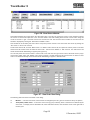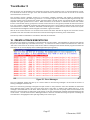
1
TRACK BUILDER 3
User Manual
6 December, 2000
Copyright 2000 Signal Computer Consultants
All rights reserved
Track Builder 3
Signal Computer Consultants
P.O. Box 18445
Pittsburgh, PA 15236
Tel. 888 872-4612 (toll free US and Canada only)
Tel. 412 655-1884
Fax. 412 655-1893
E-mail [email protected]
Web Page www.signalcc.com
Train Dispatcher 3 and Track Builder 3 are dedicated to
Frank Bryan and Fred Frailey who tested both programs
over a four month period and provided many suggestions
on improvements.
It is doubtful that these programs could have been
successfully completed without their help and support.
Page ii
6 December, 2000
Track Builder 3
Table of Contents
1.
1.1.
1.2.
2.
3.
4.
5.
5.1.
5.2.
5.3.
6.
6.1.
6.2.
6.3.
6.4.
6.5.
6.6.
7.
7.1.
7.1.1.
7.1.2.
7.1.3.
7.1.4.
7.1.5.
7.2.
7.2.1.
7.2.2.
7.2.3.
7.2.4.
7.2.5.
7.3.
7.3.1.
7.3.2.
7.3.3.
7.3.4.
7.3.5.
7.3.6.
7.4.
7.4.1.
7.4.2.
7.4.3.
7.4.4.
7.4.5.
7.4.6.
7.5.
7.6.
7.7.
7.7.1.
7.7.2.
7.7.3.
7.7.4.
7.8.
7.9.
7.10.
8.
8.1.
INSTALLATION .................................................................................................................................................................................... 1
Loading the Program........................................................................................................................................................................................1
Starting the Program .......................................................................................................................................................................................1
BRIEF OVERVIEW............................................................................................................................................................................... 1
WHAT’S NEW...................................................................................................................................................................................... 2
TERRITORY LIBRARIES.................................................................................................................................................................... 3
DESIGNING A SIMPLE TRACK LAYOUT.................................................................................................................................... 3
Track Layout Grid Screen ...............................................................................................................................................................................3
Drawing Symbols on the Grid .......................................................................................................................................................................4
Drawing a Simple Single Line Territory ....................................................................................................................................................5
TRACK BUILDER 3 TERMS AND RULES .................................................................................................................................. 9
Track Block Definition and Linkage.............................................................................................................................................................9
Switch Definition and Linkage ....................................................................................................................................................................12
Diamonds Definition and Linkage.............................................................................................................................................................12
Signal Definition and Linkage......................................................................................................................................................................12
Automatic Linking ............................................................................................................................................................................................14
Combining Blocks ............................................................................................................................................................................................15
DRAWING FUNCTIONS ................................................................................................................................................................ 15
Editing Functions..............................................................................................................................................................................................15
Selecting a Group of Grid Squares ..........................................................................................................................................................15
Deleting a Selected Group of Squares...................................................................................................................................................16
Duplicating a Selected Group of Squares ............................................................................................................................................16
Moving a Selected Group Of Squares ....................................................................................................................................................16
Deleting Symbols from the Track Layout .............................................................................................................................................17
Station Names ..................................................................................................................................................................................................17
Adding Station Names ..................................................................................................................................................................................17
Modifying Station Names.............................................................................................................................................................................18
Moving Station Names..................................................................................................................................................................................18
Deleting Station Names ...............................................................................................................................................................................18
Changing Station Names .............................................................................................................................................................................18
User Text Areas ...............................................................................................................................................................................................18
Adding Text Areas...........................................................................................................................................................................................18
Modifying Text ...................................................................................................................................................................................................19
Moving Text Areas ..........................................................................................................................................................................................19
Deleting Text Areas ........................................................................................................................................................................................19
Changing Text Areas......................................................................................................................................................................................20
Duplicating Text Area ....................................................................................................................................................................................20
Bitmaps (User Generated Graphics)......................................................................................................................................................20
Adding Bitmaps ................................................................................................................................................................................................20
Modifying Bitmaps...........................................................................................................................................................................................21
Moving Bitmaps................................................................................................................................................................................................21
Deleting Bitmaps .............................................................................................................................................................................................21
Changing Bitmaps ...........................................................................................................................................................................................21
Duplicating Bitmaps .......................................................................................................................................................................................21
Bitmap Maintenance .....................................................................................................................................................................................22
Background and Foreground General Rules ......................................................................................................................................22
Track Layout File Maintenance .................................................................................................................................................................23
New Track Layout File ...................................................................................................................................................................................23
Saving a Layout File.........................................................................................................................................................................................23
Opening an Existing Track Layout File ....................................................................................................................................................23
Loading an Existing Track Execute File ..................................................................................................................................................23
“Undo” Function................................................................................................................................................................................................24
General Drawing Guidelines........................................................................................................................................................................24
Miscellaneous Drawing Symbols..............................................................................................................................................................24
TRACK AND TRAIN FUNCTIONS .............................................................................................................................................. 24
Designing a Territory .....................................................................................................................................................................................25
Page i
6 December, 2000
Track Builder 3
8.2.
8.3.
8.4.
8.5.
8.5.1.
8.5.2.
8.6.
8.7.
8.8.
8.9.
8.9.1.
8.9.2.
8.9.3.
8.9.4.
8.10.
8.11.
8.12.
8.13.
8.14.
8.15.
8.16.
9.
9.1.
9.2.
9.3.
9.4.
10.
10.1.
11.
12.
13.
Territory Options.............................................................................................................................................................................................. 25
Block Properties .............................................................................................................................................................................................. 26
Switch Information.......................................................................................................................................................................................... 32
Diamond Information..................................................................................................................................................................................... 33
Automatic Signaling of Diamonds............................................................................................................................................................ 34
Diamond Train Frequency ........................................................................................................................................................................... 35
Signal Information ........................................................................................................................................................................................... 36
Train Type Descriptions ............................................................................................................................................................................... 37
Platform Names .............................................................................................................................................................................................. 38
Train Data........................................................................................................................................................................................................... 39
Train Data – General Dialog ...................................................................................................................................................................... 41
Train Data – Multiple Entries Dialog ...................................................................................................................................................... 42
Train Data – Work Schedule Dialog....................................................................................................................................................... 43
Train Data - Passenger Schedule Dialog.............................................................................................................................................. 44
Entrance/Exit Locations.............................................................................................................................................................................. 45
Simulation Start Times ................................................................................................................................................................................. 47
Wayside Detectors......................................................................................................................................................................................... 49
OS Names........................................................................................................................................................................................................... 50
Block Permits.................................................................................................................................................................................................... 51
Slow Orders ....................................................................................................................................................................................................... 52
Territory Data ................................................................................................................................................................................................... 54
MISCELLANEOUS TOOLS .............................................................................................................................................................55
Find Areas, Blocks, Diamonds, Switches and Signals .................................................................................................................... 55
Automatically Assign Connecting Lines ................................................................................................................................................ 56
Display Block, Diamond, Switch and Signal Numbers .................................................................................................................... 56
Re-number Blocks, Diamonds, Switches and Signals..................................................................................................................... 56
CREATE A TRACK EXECUTE FILE ..............................................................................................................................................57
Error Messages............................................................................................................................................................................................... 58
TECHNICAL SUPPORT...................................................................................................................................................................69
WARRANTY.......................................................................................................................................................................................69
SYSTEM SPECIFICATIONS...........................................................................................................................................................69
Page ii
6 December, 2000
Track Builder 3
List of Figures
Figure 1 -Track Layout Grid .....................................................................................................................................................4
Figure 2 - Interlocking Drawing ...............................................................................................................................................5
Figure 3 - Block – General Information....................................................................................................................................6
Figure 4 - Entrance/Exit Name Added......................................................................................................................................7
Figure 5 - Start Times Window.................................................................................................................................................7
Figure 6 - Train Type Dialog ....................................................................................................................................................8
Figure 7 - Add New Train Dialog .............................................................................................................................................8
Figure 8 - Train Data Window ..................................................................................................................................................9
Figure 9 - Block Limitations Examples ..................................................................................................................................10
Figure 10 - Real Blocks and Connecting Lines.......................................................................................................................10
Figure 11 - Block Links ..........................................................................................................................................................11
Figure 12 - Manual Block Linkages........................................................................................................................................11
Figure 13 - Manual Linkage Results .......................................................................................................................................11
Figure 14 - Switch Linkages ...................................................................................................................................................12
Figure 15 - Diamond Linkages ...............................................................................................................................................12
Figure 16 - Automatically Add Signals ..................................................................................................................................13
Figure 17 - New Signals (Right Hand Signaling Option) .......................................................................................................14
Figure 18 - Signal Information................................................................................................................................................14
Figure 19 - Automatic Linking Exceptions.............................................................................................................................15
Figure 20 - Selecting a Group of Squares ...............................................................................................................................16
Figure 21 - Adding a Station Name ........................................................................................................................................17
Figure 22 - Added Station Name ............................................................................................................................................18
Figure 23 - Adding Text..........................................................................................................................................................19
Figure 24 - Adding a Bitmap ..................................................................................................................................................20
Figure 25 - Foreground and Background Bitmaps..................................................................................................................21
Figure 26 - Bitmap Maintenance.............................................................................................................................................22
Figure 27 - Straight Track Symbols ........................................................................................................................................24
Figure 28 - Miscellaneous Symbols ........................................................................................................................................24
Figure 29 - Territory Options..................................................................................................................................................26
Figure 30 - Track Block Status Line .......................................................................................................................................26
Figure 31 - Block Properties - General ...................................................................................................................................27
Figure 32 - Block Properties - Speed ......................................................................................................................................30
Figure 33 - Switch Properties..................................................................................................................................................32
Figure 34 - Diamond Properties..............................................................................................................................................34
Figure 35 - Diamond Train Frequency Examples ...................................................................................................................35
Figure 36 - Double Track Junction .........................................................................................................................................36
Figure 37 - Signal Properties ..................................................................................................................................................36
Figure 38 - Train Type Data Window.....................................................................................................................................37
Figure 39 - Train Type Dialog ................................................................................................................................................38
Figure 40 - Station Platform Window .....................................................................................................................................39
Figure 41 - Station Platform Example ....................................................................................................................................39
Figure 42 - Train Data Window ..............................................................................................................................................40
Figure 43 - Train Data – General Dialog ................................................................................................................................41
Figure 44 - Train Data – Multiple Entries Dialog ...................................................................................................................42
Figure 45 - Train Data – Work Schedule Dialog ....................................................................................................................43
Figure 46 - Train Data – Passenger Schedule Dialog .............................................................................................................44
Figure 47 - Entrance/Exit Location Window ..........................................................................................................................46
Figure 48 - Entrance/Exit Location Data Dialog.....................................................................................................................46
Figure 49 - Start Times Window.............................................................................................................................................47
Figure 50 - Start Time Data Dialog.........................................................................................................................................48
Figure 51 - Wayside Detector Data Window ..........................................................................................................................49
Page iii
6 December, 2000
Track Builder 3
Figure 52 - Wayside Detectors Dialog ................................................................................................................................... 50
Figure 53 - OS Data Window ................................................................................................................................................. 51
Figure 54 - Block Permits Window........................................................................................................................................ 51
Figure 55 - Block Permit Dialog ............................................................................................................................................ 52
Figure 56 - Slow Orders Window........................................................................................................................................... 53
Figure 57 - Slow Order Data Dialog ...................................................................................................................................... 53
Figure 58 -Territory Data Dialog............................................................................................................................................ 54
Figure 59 - Territory Comments File ..................................................................................................................................... 55
Figure 60 - Find Information .................................................................................................................................................. 56
Figure 61 - Error Messages .................................................................................................................................................... 57
Figure 62 - Highlighted Track Elements ................................................................................................................................ 58
Page iv
6 December, 2000
Track Builder 3
1. INSTALLATION
1.1. Loading the Program
Track Builder 3 is a 32-bit Windows program which will run on systems running Windows 95, 98, 2000, NT 3.51 or NT
4.0 or later. It will not run under Windows 3.1.
Track Builder comes on a CD-ROM. To install the program, insert the CD-ROM into the CD-ROM drive and click the
Start and then the Run buttons. In the Open box, type d:autorun.exe if your CD-ROM is the D drive on your computer. If
it is not the D drive, type the drive letter followed by a colon and then autorun.exe (ex. e:autorun.exe, f:autorun.exe, etc.).
Follow the instructions in the installation program to complete the installation. The Setup program will ask you for a
serial number. The serial number for Track Builder is the same serial number you received for Train Dispatcher.
When Track Builder is installed, the Setup program will load the program into the Train2 folder (default) and create a
desktop icon.
1.2. Starting the Program
There are four ways to start the program. To start the program:
♦
Click the Start button, point to Program, then to the Train2 folder, and click on the Track Builder 3 program.
♦
Double click on the Track Builder 3 icon on the desktop.
♦
Open the Windows Explorer, find the Track Builder 3.exe file in the Train2 folder and double click on the file.
♦
Open the Window Explorer, find a previously saved layout file (layout files have a .lay file name extension) in the
Train2 folder, and double click on the file. This will cause the Track Builder 3 program to start and load the
layout file on which you clicked.
After starting the program, the Layout Display appears (see Figure 1).
2. BRIEF OVERVIEW
Track Builder 3 enables users of Train Dispatcher 3 to design their own track territories to be used with our railroad
traffic control simulator, Train Dispatcher 3. Territories as complicated as the Northeast Corridor track section from
Washington, DC to Philadelphia can be created with Track Builder 3.
There are five phases involved in designing a track territory. The first phase is drawing the track diagram on the grid
layout (see Figure 1).
The second phase is entering information for the track blocks and switches in the territory. This information includes:
♦
Block lengths
♦
Train speeds for various signal indications
♦
Location of controlled signals which allow trains to exit blocks
♦
Location of passenger platforms
♦
Switch reverse speeds
The third phase is entering information about trains, block permits (Track & Time) and slow orders. The train
information includes the type of train, the location and time a train enters the territory, the train’s passenger or work
schedule, and the train’s crew times. Block permit and slow order information includes their location and time when
they become active.
The fourth phase is entering startup information. Because the user can start the simulation on various days and at
different times, information about the location of trains already on the territory at the start of the simulation must be
specified.
Page 1
6 December, 2000
Track Builder 3
Information from the first four phases is stored in the layout file whose name can be specified by the user. Layout files
have a file name extension of .lay. The fifth phase uses the layout file to create a track execute file, which is the type of
file that will be interfaced with Train Dispatcher 3. Before the track execute file is created, Track Builder 3 will check the
data in the layout to insure that it is complete, consistent and in accordance with the Track Builder 3 design
parameters. If the user has entered incorrect data, Track Builder 3 will provide the user with a list of errors.
Building track territories can be a complicated task. With Track Builder 3 we have automated many of the functions to
make it easy to build single or double line territories. For the design of more complex territories, however, the user can
override these automated functions to provide additional flexibility. With this additional flexibility, territories much more
complicated than the Northeast Corridor can be designed.
This manual is divided into four sections. The first section begins at Paragraph 5 and walks a user through the creation
of a simple single line territory. The second section begins at Paragraph 6, defines terms, and explains how Track
Builder 3 builds territories. The third section begins at Paragraph 8 and describes in detail all of the features of Track
Builder 3. The fourth and final section begins at Paragraph 10 and explains the various error messages Track Builder 3
can generate when it creates a track execute file from a layout file.
To help users further, Track Builder 3 comes with a number of sample track layouts. It has the track layouts for the
Northeast Corridor track section between Washington, DC and Philadelphia and the four other territories that are
included in Train Dispatcher 3.
3. WHAT’S NEW
Train Dispatcher 3 and Track Builder 3 have been designed to meet the requirements of a major Class I railroad and
also include many of the suggestions from our Train Dispatcher 2 and Track Builder customers. The following is a brief
list of some of the new features of Track Builder 3:
♦
The number of blocks, switches, signals, platforms, trains, slow orders and block permits have been increased.
The following table lists the new maximum numbers:
ITEM
OLD MAXIMUM NUMBER
NEW MAXIMUM NUMBER
Blocks
600
2000
Switches
250
1000
Signals
250
1000
10
100
4
10
200
1000
Block Permits
40
300
Slow Orders
40
200
Entrance/Exits
50
200
Platforms
Train Types
Trains
♦
Diamonds (at grade crossovers) can now be inserted.
♦
Simulations can run for multiple days (up to 90).
♦
Different block speeds for each direction of travel can be specified.
♦
Block speeds can be specified in feet, miles, meters, kilometers or run times.
♦
Train startup times can be specified for different train types in each block.
♦
Helper requirements can be specified for each train type for each block.
♦
Signals can be automatically created for both right and left hand signaling systems.
♦
Train crew time information can be entered.
Page 2
6 December, 2000
Track Builder 3
♦
OS points can be entered.
♦
Trains can now be scheduled to become new trains or split into two trains.
♦
Local work schedules can be entered.
♦
Block permits and slow orders can be scheduled for different days of the week.
♦
Slow orders can be made permanent.
♦
Information on the territory allows for the entry of more specific information about the territory.
♦
A comments file can be added to a layout file. This greatly increases the size of the comment text that can be
associated with a territory.
♦
Train icons can be added to a layout file.
♦
Multiple simulation start times can be specified.
♦
Multiple detector types can be specified
♦
Train schedules and block speeds can be imported from text delimited files and exported to text delimited files
♦
Multiple train schedule and block speed templates can be created and inserted into new or existing trains or
blocks.
Track Builder 3 can convert Track Builder 2 layout files and Train Dispatcher 2 track files to Track Builder 3 layout files.
Track Builder 3 cannot create Train Dispatcher 2 track files. It can only create track files that can be used by Train
Dispatcher 3.
Track Builder 2 and Track Builder 3, however, can coexist in the same computer.
Please note that the term “Dummy Block” referred to in Track Builder 2 is called “Connecting Line” or “Connector” in
Track Builder 3.
4. TERRITORY LIBRARIES
Signal Computer Consultants will be maintaining two libraries of territory files on our Web Page. It is our hope that one
day these libraries will contain territory files for all Centralized Traffic Control (CTC) territories worldwide.
We encourage owners of Track Builder 3 to contribute territory files to our libraries. You can contribute either to the
Customer Contributed (free) Library, which will allow Train Dispatcher 3 owners to download and use the territory file
you contribute at no charge, or you can submit for inclusion in the For Sale (paid) Library. If we decide to add your
territory to the For Sale Library we will pay you a 15% commission on the sales of your territory file. The commission
will be paid on the $5.00 (Track Builder 2 territories) or $7.00 (Track Builder 3 territories) per territory purchase price
excluding shipping and handling charges and sales tax.
5. DESIGNING A SIMPLE TRACK LAYOUT
5.1. Track Layout Grid Screen
The first screen that appears when you run Track Builder 3 is shown in Figure 1. This screen displays the track layout
grid for a track layout file called “sample1.lay”. The name of the track layout file currently being displayed appears in the
top left hand corner of the screen under the menu bar.
Page 3
6 December, 2000
Track Builder 3
Name of the
layout file
Interlocking
drawing tools
Drawing tools
Mouse grid
location
Device status
line
Figure 1 -Track Layout Grid
At the bottom left hand corner of the screen you will see the x (horizontal) and y (vertical) grid coordinates of the mouse.
As you move the mouse pointer around from one grid square to another you will see the coordinates change.
To the right of the grid coordinates you will see the device status line. If you place the mouse pointer on a signal (the
signal’s left most grid square), switch, or track symbol on the grid, information about that device will appear in the status
line. A detailed explanation of the information displayed in the status line can be found in Paragraph 8.
On the left hand side of the screen are a number of drawing tools or buttons that represent tracks, signals, switches
and various other devices. The meaning of each of these symbols will be discussed later in this manual.
The last area of interest on the screen is at the top and to the right of the “Save” button. Located there are nine
interlocking drawing tools or buttons. These tools will also be discussed later in this manual.
5.2. Drawing Symbols on the Grid
It is very simple to draw a track device symbol on the grid. Place the mouse pointer on a drawing tool such as the
straight track line, which is the top, left-most drawing tool. Click the left mouse button, which will turn the drawing tool
gray, and move the pointer over the grid. Once the mouse moves over the grid it will change from a pointer to an icon
representing the symbol you have just selected. Move the pointer to the grid square on which you want to place the
symbol and click the left button. The symbol is now drawn on the track layout grid. If you move the pointer one grid
square to the right and click the left mouse button again, the symbol will now also be drawn on this grid square.
To erase a symbol from a grid square, place the mouse pointer on the grid square and press the “delete” key or doubleclick the left mouse button. The symbol has now been erased from the grid square.
Page 4
6 December, 2000
Track Builder 3
5.3. Drawing a Simple Single Line Territory
The first task in drawing a new territory is to create a new track layout file. To do this click on the item in the menu bar
called “File”. On the pop-up menu that appears select the “New Track Layout File”. Because (if you followed the
instructions in Paragraph 5.2) you have modified the “sample1.lay” file, the program will now ask if you want to save the
changes you made to this file. Answer “No”.
The grid will now be cleared of all drawing symbols and the track layout file name will be “new1.lay”. You can now begin
drawing a new territory layout.
Because we are going to draw a simple single line territory, we can use some of the interlocking drawing tools that are
located to the right of the “Undo” and “Save” buttons. The interlocking tools draw a group of drawing symbols on the
grid that represent an interlocking type. This is a much quicker way to draw standard interlockings than by using
individual drawing tools.
Start by placing the mouse pointer on the left interlocking button (just right of the “Save” button), and click the left
mouse button. The interlocking button will turn gray, and, as you move the mouse pointer over the grid area, it will turn
to an icon representing the interlocking type.
Place the mouse on grid square x = 3, y =3 and click the left mouse button again. The interlocking will now be drawn on
the grid and have a blue background (see Figure 2).
Figure 2 - Interlocking Drawing
If you now move the mouse pointer to any grid square that is not blue and click the left button, the blue background will
disappear.
Now click the second from the left interlocking tool, place the mouse pointer on grid square x = 11, y = 3, and click the
left button. Again move the mouse pointer to a grid square that is not blue and click the left mouse button. You have
now drawn a complete single line siding with switches and signals.
Add another siding to the territory by again selecting the left most interlocking drawing tool and placing it at grid square
x = 19, y = 4. You will notice the new interlocking does not line up with the previous interlocking.
When a group of grid squares are in blue it means they are selected and can be moved as a group to another location.
You need to move this group one grid square to the left and one grid square up to line up with the previous interlocking.
To do this place the mouse pointer on any one of the blue grid squares and hold down the left mouse button. A dark
blue rectangle will appear around the selected grid area. To move the group, continue holding down the left mouse
button, drag the rectangle to the new location, and then release the left button. The interlocking should now be aligned
with the previous interlocking. If not, move it to the correct position using the same procedure. After positioning it
correctly and releasing the left mouse button, move the mouse to any location outside of the interlocking (selected
squares) and again click the left mouse button, which will deselect the group of grid squares. Now select the
interlocking type that is second from the left again and place it at grid location x = 27, y =3.
You are almost done designing the territory. There are still two more things to do. You may have noticed that some of
the track blocks are gray while others are black. If you place the mouse pointer on a gray track block, in the device
status line at the bottom of the screen you will see it has a name of “Connector”, which means the block is a connecting
Page 5
6 December, 2000
Track Builder 3
line. Now place the mouse pointer on a track block that is black. Its name is “None” and it has a length of 5280 feet.
Any track block that is black (has length) is a real track block that can hold a train. Because Train Dispatcher 3 must be
able to display train icons and/or train identification characters in blocks that hold trains, space must be provided to
display these items. Real track blocks must, therefore, have at least three adjacent grid squares that contain straight
track drawing symbols to display train icons and identification characters. A detailed explanation of real and connecting
lines is given in Paragraph 6.1.
The track blocks starting at x = 3, y = 6 and x = 33, y = 3 are black and do not have three adjacent straight track
symbols. You must add straight track symbols to grid squares x = 1, y = 6; x = 2, y = 6; and x = 35, y = 6 by clicking the
straight track symbol tool and then clicking on the appropriate grid squares.
The track blocks starting at x = 1, y = 6 and ending at x = 35, y = 6 are open ended since they do not have any blocks or
switches to their left or right, respectively. Territory entrance/exit names must be assigned to these open-ended track
blocks.
To assign these names, first click the right mouse button anywhere on any grid square that does not contain a drawing
symbol. The mouse pointer will become an arrow. Place the mouse pointer on grid square x = 1, y = 6 and click the
right mouse button again. A secondary menu will appear which contains four items. Click the “Properties - General”
menu item, and the display in Figure 3 will appear.
Left entrance/
exit name
Figure 3 - Block – General Information
Type “A1” into the top-most “Entrance/Exit Name” field. The top most “Entrance/Exit Name” field is for an
entrance/exit that is to the left of the block, and the bottom most “Entrance/Exit Name” field is for an entrance/exit to
the right of the block.
Page 6
6 December, 2000
Track Builder 3
Figure 4 - Entrance/Exit Name Added
The same operation must be performed for the track block that starts at x = 33, y = 6 except the entrance/exit will be
to the right of the block. Type “B1” into the bottom-most “Entrance/Exit Name” field. Click “OK” at the bottom of the
display. “A1” will now appear to the left of the block on the track layout screen (see Figure 4) and “B1” will appear to the
right of the block on the track layout screen.
You still have one more step before you have finished completing the layout file. You must assign at least one simulation
start time. To add a start time click the “Data” item in the menu bar at the top of the screen and then select the “Start
Times” menu item. A Start Times window will appear (see Figure 5).
Figure 5 - Start Times Window
To add a new start time, click the new button which will cause a Start Time Data dialog to appear. Click the OK button to
add a new start time and then close the Start Times window. An explanation on adding new start times can be found in
Paragraph 8.11.
Your track layout is now complete. Train Dispatcher 3, however, cannot use the layout you just completed until you
create a track execute file. The information you have been entering is stored in a layout file which has an extension of
“.lay”. A track execute file, which has an extension of “.trk”, must be created from the information stored in the track
layout file. To create a track execute file select the “Create Track Execute File” item under the “File” menu.
You should receive a message telling you that you had no errors, but did have warnings and asking if you want to
continue building the track execute file. Answer “Yes”.
The next message will tell you that you successfully created a track execute file. At this point you could insert the track
execute file into Train Dispatcher 3 and throw switches and clear routes. However, there would be no trains because
you have not yet entered any information about the trains that will run on this territory. There are two steps to adding
trains to a new territory. First, you must define at least one train type, and second, you must add the trains.
To add a train type, select the “Train Type Description” item under the “Data” menu. This will cause a Train Type Data
window to appear. Click the “New” button in this window, and the Train Type dialog will appear (see Figure 6).
Page 7
6 December, 2000
Track Builder 3
Figure 6 - Train Type Dialog
Enter “Freight” in the “Description” field and click the “OK” button to exit the Train Type Data window. More information
about entering train types can be found in Paragraph 8.7.
To enter the information about the trains, select the Train Data” item in the “Data” menu of Track Builder 3. This will
cause the Train Data window to display. To add a train click the “Add” button, and the “Add New Train” dialog displayed
in Figure 7 will appear.
Figure 7 - Add New Train Dialog
For this sample enter “Test1” in the “Train ID” field, make the initial train direction to the right, enter “Freight” into the
“Train Type” field, enter “A1” into the “Train enters at location” field, enter “0005” (24 hour military time) into the “at
time” field and enter “B1” into the “Train exits at location” field. Click the “OK” button. The train will now appear in the
Train Data window (see Figure 8).
Page 8
6 December, 2000
Track Builder 3
Figure 8 - Train Data Window
This set of instructions will tell Train Dispatcher 3 that a train called “Test1” will enter the territory at entrance/exit
location “A1” at 5 minutes after midnight. The train will initially be moving from left to right across the screen and the
intended exit point is at “B1”.
You can add additional trains to the territory in the same manner as above. Up to 1000 trains can be added.
You will now have to again create the track execute file by clicking on “Create Track Execute File” under the “File” menu
and responding “Yes” to the prompt that will follow.
You are now ready to insert this territory, including the trains, into Train Dispatcher 3. Follow the instructions in the
Train Dispatcher 3 manual on how to change the name of the track execute file. Use the track execute file name you
assigned to this territory via Track Builder 3. When you run Train Dispatcher 3, the simulation will occur on the
territory you built with the trains you created using Track Builder 3.
6. TRACK BUILDER 3 TERMS AND RULES
There are four basic building elements used to create a territory. These are track blocks, switches, diamonds, and
signals. All of these elements must be linked together to create a territory. Track Builder 3 automatically creates these
linkages for you, but you can override this automatic feature and provide your own linkages. The following describes
these elements and rules governing their linkage.
6.1. Track Block Definition and Linkage
A track block consists of a group of track symbols displayed on the screen. Track Builder 3 automatically groups these
symbols into blocks and assigns a unique number to each block. The limits of a block are determined by the track
symbols the user draws. The best way to demonstrate this is to show some examples (see Figure 9). Track Builder 3
can also display the block numbers on the screen. These are located near each track symbol. To turn this feature on,
select “Display Block Numbers” under the “Tools” menu.
There are four basic rules the program uses to define the limits of a block. Any one of the following causes the
termination of a block:
♦
Adjacent track symbols do not align
♦
The user draws a track symbol which has either a vertical or horizontal bar
♦
The user draws a switch
♦
The user draws a diamond
Page 9
6 December, 2000
Track Builder 3
Track symbols
do not line up
Tracks with
vertical bars
define the end of
blocks
Switches and
diamonds define
the end of blocks
Tracks with
horizontal bars
define the end of
blocks
Figure 9 - Block Limitations Examples
Track blocks can either represent real physical signal blocks on a territory or be connecting (drawing) lines. Real blocks
have length and can hold a train. Real blocks are drawn in black. Connecting lines are drawn in gray.
Track Builder 3 uses connecting lines for a multitude of purposes. They are used to give a clean organized look to the
display and to provide interconnections between real blocks and switches or diamonds in interlockings (see Figure 10).
Figure 10 - Real Blocks and Connecting Lines
Both real blocks and connecting lines must be linked to the other track elements to their left and right. Track Builder 3
automatically creates these links. In Figure 11 the status line at the bottom of the screen shows that Block 2’s left link
is “B 1” (Block 1) and right link is “B 3” (Block 3). For Block 3 the status line would show its left link as “B 2” and its right
link as “S 0” (Switch 0).
Page 10
6 December, 2000
Track Builder 3
Figure 11 - Block Links
You can override this linking by using the “Block Properties” dialog which is called up by pointing the mouse to any one of
the track symbols making up the block, clicking the right mouse button once or twice to display the pop-up menu, and
selecting the “Properties - General” menu item. In the “Right device - Manual block” field in Figure 12 we assigned Block
5 as the device to right of Block 4.
Right device –
Manual block
field
Figure 12 - Manual Block Linkages
You can only make manual linkage assignments to blocks. In Figure 13 we see that Block 4 is now linked to the right to
Block 5. Manual linkages are primarily to link blocks on the right side of a screen at the end of a track line to blocks on
the left end of the screen that start a new track line.
Figure 13 - Manual Linkage Results
Page 11
6 December, 2000
Track Builder 3
6.2. Switch Definition and Linkage
Switches allow users to change train routes. Each switch has two positions, which are called normal and reverse. The
normal switch position is for moves straight through the switch, and the reverse position is for moves on an angle to the
straight alignment.
Each switch is automatically assigned a unique number by Track Builder 3 and linked to other track elements. However,
unlike track blocks that have two only linkages, switches have three. These are normal left, normal right and reverse. In
Figure 14 see in the status line that Switch 0 (the top most switch) is linked to Block 0 to the left, to Block 2 to the right,
and in the reverse position to Block 1.
Figure 14 - Switch Linkages
Switches can be linked to other switches, as we see in the figure above. The automatic switch linkages cannot be
overridden by manual linkages.
6.3. Diamonds Definition and Linkage
Diamonds allow one track to make at grade crossing of another track. Each diamond is automatically assigned a unique
number by Track Builder 3 and linked to other track elements. However, unlike track blocks that have two linkages or
switches that have three linkages, diamonds have four linkages. These are left, right, top, and bottom. In Figure 15 we
see in the status line that Diamond 0 (the left-most diamond) is linked to Block 0 to the left, to Block 1 to the right, and
to Block 3 to the top and to Block 2 to the bottom.
Figure 15 - Diamond Linkages
Diamonds can be linked to other diamonds and to switches. The automatic diamond linkages cannot be overridden by
manual linkages.
6.4. Signal Definition and Linkage
Signals operate like traffic lights and allow trains to depart one block and enter another. All real track blocks (not
connecting lines) have signals that prevent more than one train from occupying a block at a given time. There are two
basic types of signals, called controlled and automatic. Automatic signals allow a train to exit one block and enter
Page 12
6 December, 2000
Track Builder 3
another when the next block is unoccupied and is not cleared for traffic moving in the opposite direction. Automatic
signals do not appear on the track layout and are not controlled by the dispatcher.
Controlled signals are signals that are controlled by the dispatcher and will appear on the track layout. The system
assumes a block has an automatic signal in any direction in which it does not have a controlled signal.
Controlled signals can be assigned to any real track block (not connecting line) displayed on the track diagram.
Controlled signals are normally located at controlled points (switches), but can be located anywhere the user wants the
dispatcher to have control over the signal.
There are three ways to add a controlled signal to a block. The easiest is to use the “Block Properties” dialog to create
left or right exit signals for a particular track block. To bring up the “ Block Properties” dialog point to a track symbol in
the block to which you want to add a controlled signal, click the right mouse button once or twice to display the pop-up
menu, and select the “Properties - General” menu item. In Figure 16 click the “Create Left” and “Create Right” buttons
to create controlled signals at both ends of the block.
Create left
signal
Create right
signal
Figure 16 - Automatically Add Signals
Figure 17 shows the new signals you created for Block 4. If the right hand signaling option is selected (see Paragraph
8.2), the base of the left signal is always located one grid square to the left and one grid square above the grid square
which contains the left most track symbol for the block. The base of the right signal is one grid square to the right and
one grid square below the right most track symbol for the block. If the left hand signaling option is selected, the signals
would be on the opposite sides of the track. If you place the mouse pointer on the left most grid square of the signal, the
status line at the bottom of the screen will show the signal number and the block to which the signal is assigned.
Page 13
6 December, 2000
Track Builder 3
Figure 17 - New Signals (Right Hand Signaling Option)
Another way to add a controlled signal to a block is to use the signal drawing tool to place a signal on the grid. Once
drawn on the grid, the signal will automatically try to attach itself to a block. If the right hand signaling option is selected,
left signals will check the grid square which is one grid square down and one grid square to the right of the grid square
holding the base of the signal. If a real block’s track symbol is located in the grid square, the signal will be assigned to
that block. Right signals will check the grid square which is one grid square above and one grid square to the left of the
grid square holding the base of the signal. Again, if a real block’s track symbol is in that grid square, the signal will
automatically be assigned to that block.
Signals can also be manually assigned to blocks. To do this place the mouse pointer on the left most grid square of the
signal, click the right mouse button once or twice, and a pop-up menu will appear. Selecting the “Properties” menu item
will display the Signal Information dialog as shown in Figure 18.
Figure 18 - Signal Information
To manually assign a signal to a block number, uncheck the “Automatic link to block” box and enter the block to which
you want the signal linked. Please note that if you move the track without moving the signal, the manual block
assignment may be lost.
6.5. Automatic Linking
Track Builder 3 automatically links track elements if the track elements line up with each other. There are a few
exceptions to this rule. Figure 19 shows some examples of when Track Builder 3 will not link adjacent track elements. In
this figure Block 12 will not link to Block 4 or 5 because the adjacent track elements do not line up. Block 6 will not link
to Block 0 because there is gap a between the blocks. Block 8 will not link to Block 7 even though they appear to line up.
There must always be a complete vertical track symbol between two vertical blocks in order for automatic linking to
occur.
Page 14
6 December, 2000
Track Builder 3
Block 12 will
not link with
4 or 5
Block 11 will
link with 9 and
10, see the
status line
Block 7 and
8 will not
properly link
Figure 19 - Automatic Linking Exceptions
A vertical track symbol does not technically have a left or a right. For vertical track symbols the top is considered left
and the bottom right. The status line at the bottom of the screen shows the information for Block 11. You can see that
Block 10 is linked to the left or top and Block 9 to the right or bottom.
Before a track execute file can be created for Train Dispatcher 3, Track Builder 3 will check to see that every track
element is properly linked to other track elements. The only exception is for track blocks that go off the territory. Track
blocks that go off the territory must have an entrance/exit name assigned to the end that is not connected to other
track elements.
6.6. Combining Blocks
In Figure 19 you can combine Block 6 with Block 0 by placing a straight track symbol between the two blocks. When
the two blocks are combined, all track symbols associated with Block 0 will now become part of Block 6. When two
blocks are combined in this fashion, the new block will have the number and characteristics of the left-most block prior
to the combination. For example, if Block 6 had a length of 2 miles and Block 0 a length of 1 mile, the combined block
will be the same as Block 6 and have a length of 2 miles.
7. DRAWING FUNCTIONS
7.1. Editing Functions
Track Builder 3 has a number of features to help the user draw, delete and move items around on the screen. The
following paragraphs describe these:
7.1.1. Selecting a Group of Grid Squares
To make it easier to design a track layout, the user can select a group of grid squares that can be moved, deleted or
duplicated as an intact group. The bottom right button in the left hand tool bar is used to select a group of squares.
When this button is clicked the mouse pointer will turn to cross hairs when it is moved over the grid. To select a group
of grid squares, place the mouse pointer on the grid square just above and to the left of the top, left-most square in the
group you want to select, hold down the left button, and then drag the pointer to the grid square just below and to the
right of the intended group. While dragging the pointer, a blue rectangle appears that encompasses the selected
squares. When you release the left button the selected squares will become light blue (see Figure 20).
Page 15
6 December, 2000
Track Builder 3
Selection
button
Selection
grid
Pop-up
menu
Figure 20 - Selecting a Group of Squares
7.1.2. Deleting a Selected Group of Squares
To clear all of the squares in this group, place the mouse pointer on any square in the selected group and perform one
of the following:
♦
press the “Delete” key
♦
double click the left mouse button
♦
click the right button to cause a pop-up menu to appear and choose the “Delete grid squares” menu item.
If you make a mistake you can always click on “Undo” in the top tool bar to return the layout to the configuration prior to
your last change.
7.1.3. Duplicating a Selected Group of Squares
A user can duplicate a selected group of grid squares by placing the mouse pointer on any square in the selected group,
clicking the right button to call up the pop-up menu, and selecting the “Duplicate” menu item. The duplicated group will
appear below and to the right of the originally selected group of squares.
7.1.4. Moving a Selected Group Of Squares
To move the selected group to another location on the grid, place the cursor on any grid square in the selected group,
hold the left mouse down and drag the group to another location. A blue rectangle equal to the size of the selected
group will appear and move with the cursor. As you move the selected rectangle to the edge of the screen, the system
will automatically scroll the screen in the direction of your movement. When you release the left button the selected
group will move to the new location, but will not change any symbols it may have overlaid until the group of squares is
deselected. This feature allows the user to move the selected group again, without affecting the grid squares it overlaid.
Once deselected, the symbols the group overlaid will be replaced by the symbols in the selected group. Again, you can
use the “Undo” button to return the display to its configuration before the group was moved.
If the first straight track symbol in a named track is moved as part of this selected group, the track name will move with
the symbol. The track name will disappear from the remaining straight track symbols that were not moved.
To deselect a group, place the cursor on any grid square outside of the selected group and click the left mouse button.
Page 16
6 December, 2000
Track Builder 3
7.1.5. Deleting Symbols from the Track Layout
There are several ways to clear a symbol from a grid square. These all start by placing the mouse pointer on the
square that contains the symbol to be deleted. Once the pointer is on the grid square you can do any one of the
following:
♦
press the “Delete” key,
♦
double click the left mouse button,
♦
click the right mouse button to cause a pop-up menu to appear and choose the “Delete grid squares” menu
item.
If you make a mistake you can always click the “Undo” button in the top tool bar to return the layout to the configuration
prior to your last change.
7.2. Station Names
The user can add station names to interlockings on the track layout. The user can specify the font, font size, color of the
text, and station call-up character. The call-up character has two functions. In Train Dispatcher 3, if the user wants to
quickly move the screen to a station that has a call-up character of “A”, all he or she must do is press “A” on the
keyboard, and the screen will be scrolled to that station. Call-up characters are also used to name track sections (see
Paragraph 8.3). A track section that is between two stations (interlockings) that have call-up characters of “A” and “B”
would have these two characters incorporated into its name so a user can easily find the track section on the screen.
Station call-up characters should be judiciously assigned. The limit of station call-up characters is the number of letters
in the alphabet. There can be many more stations than that in Track Builder 3; therefore, in territories having more
than 26 stations, some will not have call-up characters.
7.2.1. Adding Station Names
The user adds a station name by clicking on the “Stat” button in the vertical tool bar, placing the mouse pointer at the
location on the grid where the station name is to be placed, and clicking the left mouse button. These actions cause
Figure 21 to be displayed.
Figure 21 - Adding a Station Name
To add the station name the user types the name in the “Station Name” field and the call-up character in the “Station
call-up character” field. The system creates a station text box that is sized to the length of the name the user entered
for the given font and font size.
If the user wants to change the name’s font, font size or font style, the user clicks the “Font” button, and the standard
“Font” dialog will appear.
Page 17
6 December, 2000
Track Builder 3
To change the name’s color, the user clicks the “Color” button, and the standard “Color” dialog will appear. The user
then clicks on one of the color boxes for the color he or she wants to use for the name. The results of adding a station
name can be seen in Figure 22.
Figure 22 - Added Station Name
7.2.2. Modifying Station Names
Station names displayed on the track layout can be easily moved, deleted or changed. To perform any of these
operations the station name must first be selected. To select a particular station name, first click on the “Stat” button in
the vertical tool bar, and then point to the station name area that you want to modify. As soon as you point to a station
name, the mouse pointer will change in shape from the “Stat” symbol to an arrow.
7.2.3. Moving Station Names
To move a station name point to the station name, then hold down the left mouse button, which causes a blue rectangle
to appear around the station name. While holding the left button down, drag the station name to another position on
the screen. If the station name is dragged near the edge of the screen, the screen will automatically scroll in the
direction the mouse pointer is moving.
7.2.4. Deleting Station Names
There are three ways to delete a station name. First, select the station name. Then press the “Delete” key, double click
the left mouse button, or click the right mouse button. The first two options will immediately delete the station name
from the display. The last option (click the right mouse button) will cause a pop-up menu to appear. Click the “Delete
station name” item in this pop-up menu to delete the station name.
7.2.5. Changing Station Names
To change a selected station name, click the right mouse button to display the pop-up menu, and then click on the
“Properties” menu item. Figure 21 will then appear. Follow the instructions in Paragraph 7.2.1 to change the station
name’s text, font, font size, font style, color, or call-up character.
7.3. User Text Areas
The user can add text to the track layout and specify the font, font size and color of the text. The user may generate a
number of text areas (see Paragraph 13 for the number of text areas allowed).
7.3.1. Adding Text Areas
The user adds text by clicking on the “Text” button in the vertical tool bar, pointing the mouse pointer to the location in
the track layout grid where the text is to be placed, and clicking the left mouse button. Figure 23 will then be displayed.
Page 18
6 December, 2000
Track Builder 3
Figure 23 - Adding Text
To add text the user types the text in the “Text” field on the left hand side of the screen. The system creates a text box
that is sized for the amount of text the user enters for the given font and font size. The user can specify whether the
text is to be left, center or right justified by clicking the appropriate button (“Left Text”, “Center Text” or “Right Text”). The
user can also specify the text box to have a border around it by checking the “Border” check box.
If the user wants to change the text’s font, font size or font style, the user will click the Font button and the standard
“Font” dialog will appear.
To change the text color the user clicks the “Color” button, and the standard “Color” dialog will appear. The user then
clicks on one of the color boxes for the color he or she wants to use for the text.
Text areas can be displayed in the background or foreground. If in the background, all track and train symbols will be
displayed on top of the background text areas. If the user specifies the text area to be in the foreground, the text area
will be written on top of the track and train symbols. Foreground text areas also are written on top of background
bitmaps and background user text areas (see Paragraph 7.6 for more information).
7.3.2. Modifying Text
Text areas displayed on the track layout can be easily moved, deleted, changed or duplicated. To perform any of these
operations, the text area must first be selected. To select a particular text area, first click on the “Text” button in the
vertical tool bar and then point to the text area you want to modify. As soon as you point to a text area, the mouse
pointer will change in shape from the “Text” symbol to an arrow.
7.3.3. Moving Text Areas
To move a text area, select the text area as described above. Then hold down the left mouse button, which will cause a
blue rectangle to appear around the text area. While holding down the left button, drag the text area to another
position on the screen. If the text area is dragged near the edge of the screen, the screen will automatically scroll in the
direction the mouse pointer is moving.
7.3.4. Deleting Text Areas
There are three ways to delete a text area. First, select the text area. Then press the “Delete” key, double click the left
mouse button, or click the right mouse button. The first two options will immediately delete the text area from the
display. The last option (click the right mouse button) will cause a pop-up menu to appear. To delete the text area, Click
the “Delete Text” item in the pop-up menu.
Page 19
6 December, 2000
Track Builder 3
7.3.5. Changing Text Areas
To change a selected text area click the right mouse button to display the pop-up menu, and then click on the
“Properties” menu item. Follow the instructions in Paragraph 7.3.1 to change the text area’s text, font, font size, font
style, or color.
7.3.6. Duplicating Text Area
Text is duplicated in much the same way as it is deleted. Instead of clicking the “Delete Text” menu item in the pop-up
menu, click the “Duplicate” menu item. Another text area with the same characteristics as the selected text area will
appear below and to the right of the selected text area.
7.4. Bitmaps (User Generated Graphics)
The users can add their own graphics to a track layout. These graphics are in the form of bitmaps that can be copied
from a variety of sources including clip art packages, or generated by the user using software such as “Paint”. These
bitmaps may represent a railroad’s logo or physical items along the track such as buildings, roads, rivers, landmarks,
etc.
All bitmap files have a file extension of “.bmp”. The system limits a single bitmap size to 30,000 bytes and the number of
colors to 16. The user may generate a number of bitmaps (see Paragraph 13 for the number of bitmaps allowed).
7.4.1. Adding Bitmaps
The user adds bitmaps by clicking the “Bit” symbol button on the left hand side of the screen, pointing the mouse pointer
to the intended location in the track layout grid, and clicking the left mouse button. These actions cause Figure 24 to be
displayed.
Figure 24 - Adding a Bitmap
A list of available bitmaps appears in the “Bitmap Description” list box on the left hand side of the display. Each track
layout file maintains its own unique list of available bitmaps. A new track layout file will not have any bitmaps until the
user adds a bitmap to the file by use of the “Bitmap Maintenance” function. This function can be called by clicking the
“Bitmap Maintenance” button on this screen.
The display in Figure 24 shows the original width and height in pixels of an existing bitmap. The user can change the size
of a bitmap that is displayed on the track layout by changing the number of pixels in the “Current Width” and “Current
Height” fields. The user can make the displayed bitmap larger or smaller than the original.
Page 20
6 December, 2000
Track Builder 3
Bitmaps can be displayed in the background or foreground. If in the background, all track and train symbols will be
displayed on top of the bitmap. If the user specifies the bitmap to be in the foreground, the bitmap will be written on top
of the track and train symbols. Foreground bitmaps also are written on top of background bitmaps and background
user text areas (see Paragraph 7.6 for more information). Figure 25 shows the effect of adding a foreground bitmap to
the track layout.
Figure 25 - Foreground and Background Bitmaps
7.4.2. Modifying Bitmaps
Bitmaps already displayed can be easily moved, deleted, resized or duplicated. To perform any of these operations the
displayed bitmap must first be selected. To select a particular bitmap, first click the bitmap symbol on the left hand side
of the display and then point to the bitmap that you want to modify. As soon as you point to a bitmap, the mouse pointer
changes in shape from the bitmap symbol to an arrow.
7.4.3. Moving Bitmaps
To move an existing bitmap first select it as described above, then hold down the left mouse button, which will cause a
blue rectangle to appear around the bitmap. While holding down the left button, drag the bitmap to another position on
the screen. If the bitmap is dragged near the edge of the screen, the screen will automatically scroll in the direction the
mouse pointer is moving.
7.4.4. Deleting Bitmaps
There are three ways to delete a bitmap. First, select the bitmap. Then press the “Delete” key, double click the left
mouse button, or click the right mouse button. The first two operations will immediately delete the bitmap from the
display. The last operation (click the right mouse button) will cause a pop-up menu to appear. Click the “Delete Bitmap”
menu item in the pop-up menu to delete the bitmap.
7.4.5. Changing Bitmaps
To change a displayed bitmap, select the bitmap, click the right mouse button, and then click the “Properties” item in the
pop-up menu. Figure 24 will then appear. Follow the instructions in Paragraph 7.4.1 to change the displayed bitmap’s
graphics or size.
7.4.6. Duplicating Bitmaps
To duplicate a displayed bitmap, select the bitmap, click the right mouse button, and then click the “Duplicate” menu
item in the pop-up menu. Another bitmap with the same characteristics as the selected bitmap will appear below and to
the right of the selected bitmap.
Page 21
6 December, 2000
Track Builder 3
7.5. Bitmap Maintenance
Each track layout file maintains its own list of available bitmaps. The user adds, removes or changes this list through the
“Bitmap Maintenance” function. To display this function click the “Bitmap Maintenance” button in the “Insert Bitmap”
dialog (see Figure 24). Figure 26 will then appear.
Figure 26 - Bitmap Maintenance
To add a bitmap the user must enter a description of the bitmap in the “Bitmap Description” field on the right hand side
of the display and provide the bitmap’s file name including its path. To help the user find the bitmap file, the user can
click the “Browse File Name” button, which causes the standard “Open File” dialog to appear. Once a valid bitmap file
name is selected, the bitmap’s graphics will appear in the lower right hand box. The graphics shown will not be the
actual size of the bitmap, but will be sized to fit into this box. The user will receive an error message if the bitmap is not
valid or the bitmap is greater than 30,000 bits.
To add this bitmap to the track layout file click the “Add” button. Once added, the description the user entered for the
bitmap will appear in the “Bitmap Description” list box on the left hand side of the display.
To remove a bitmap or change its description or path in the track layout file, select the bitmap description in the
“Bitmap Description” list box by clicking on the description with the left mouse. The user can then remove it by clicking
the “Remove” button or change the description or file name by clicking the “Change” button.
7.6. Background and Foreground General Rules
The system was designed to provide the user with maximum flexibility in deciding how graphics and text are displayed in
Train Dispatcher 3. Part of this flexibility allows the user to designate which objects will be placed on top of other
objects on the display grid. The user controls this by designating which bitmaps and text areas are in the display’s
background or foreground. The system controls the display overlap by writing the background objects first, then the
track and train symbols, and finally the foreground objects. The following is the order in which various objects are
written to the screen in Train Dispatcher 3:
♦
Background Bitmaps
♦
Background Text Areas
♦
Track Symbols
♦
Train Symbols
Page 22
6 December, 2000
Track Builder 3
♦
Foreground Bitmaps
♦
Foreground Text Areas
♦
Station Names
If the user has several bitmaps in the background and these bitmaps overlap, the bitmap that was last selected by the
user is the bitmap that will be placed on top of the other background bitmaps. The same rule applies for two or more
foreground bitmaps or text areas.
7.7. Track Layout File Maintenance
Under the “File” menu there are a number of file maintenance functions that allow the user to create a new track layout,
save an existing track layout file, open an existing track layout file (.lay) or open an existing track execute file (.trk). The
following paragraphs describe these functions in more detail.
7.7.1. New Track Layout File
To create to new track layout file click the “New Track Layout File” menu item under the “File” menu. This will cause the
grid to clear and a file name of “newX.lay” to be created and assigned to the cleared grid. The “X” in the file name is a
number from 1 to 99. If, for example, there is an existing “new1.lay”, the new file will automatically be called “new2.lay”.
After creating the new track layout, you should give the file a more meaningful name before saving it.
If you click on the “New Track Layout File” menu item and there is an existing track layout file displayed on the grid that
had been changed since you last saved the file, the system will, before clearing the grid, ask if you want to save the
changes to the file.
7.7.2. Saving a Layout File
To save a track layout file click either the “Save Track Layout File” or “Save Track Layout File As” menu item under the
“File” menu. If you choose “Save Track Layout File” the file will be saved under its current name. If you choose “Save
Track Layout File As” the program will display a “Save As” dialog asking you to enter a file name. For new track layout
files you should always use the “Save Track Layout File As” menu item to give the file a more meaningful name.
You can also save the file under the existing name if you click the “Save” button under the menu bar at the top of the
screen. This button will only be active (not gray) if you have changed the track layout since you last saved the file.
If you save a track layout that was saved previously, the system will rename the old file by changing the extension from
“.lay” to “.~la”. This is a backup copy of your track layout file.
7.7.3. Opening an Existing Track Layout File
To open an existing track layout file click the “Open Track Layout File” item under the “File” menu. This will cause the
“Open” dialog to appear with a list of existing track layout files. You can select one of the files, change the directory, or
enter a file name.
If there is an existing layout file on the grid that has been changed since you last saved the file, the system will, before
opening and displaying the new track layout file, ask if you want to save the changes.
7.7.4. Loading an Existing Track Execute File
Track Builder 3 can load track execute files, allow you to make changes to them, and then save them as track layout
files.
To open an existing track execute file click the “Load Track Execute File” menu item under the “File” menu. This will
cause the “Open” dialog to appear with a list of existing track execute files. You can select one of the files, change the
directory, or enter a file name.
If there is an existing layout file on the grid that has been changed since you last saved the file, the system will, before
opening and displaying the new track execute file, ask if you want to save the changes.
Page 23
6 December, 2000
Track Builder 3
If you make any changes to the track execute file and attempt to save those changes, the system will save it as a track
layout file and ask you for a track layout file name.
7.8. “Undo” Function
To undo your last change to the track layout click the “Undo” button under the menu bar at the top of the screen. The
“Undo” function will only undo your last change to the track layout.
7.9. General Drawing Guidelines
Track Builder 3 will not prevent you from having conflicts in displaying track symbols, miscellaneous drawing symbols,
and train icons in Train Dispatcher 3. In Train Dispatcher 3 the train icons are the last items displayed on the screen
and will write over any drawing symbol on the screen at the same location. If possible, you should try to keep a minimum
of one blank grid square between parallel tracks to prevent this conflict.
To accommodate the space needed to display train icons and train identification characters in Train Dispatcher 3, the
system requires each real block to have at least three adjacent grid squares with straight track symbols. Figure 27
shows examples of blocks with and without three valid adjacent straight track symbols.
Blocks which do
not have three
valid adjacent
straight track
symbols
Blocks with
three valid
adjacent
straight track
symbols
Straight
track symbols
Figure 27 - Straight Track Symbols
7.10. Miscellaneous Drawing Symbols
There are four miscellaneous drawing symbols in the tool bar to the left of the track layout grid. These are shown in
Figure 28. The top left symbol represents a station platform, the top right a milepost, the bottom left a hot box
detector, and the bottom right a dragging equipment detector. These drawing symbols are each displayed in one grid
square, except for the platform symbol which takes up three horizontal grid squares.
Figure 28 - Miscellaneous Symbols
8. TRACK AND TRAIN FUNCTIONS
The following paragraphs describe in detail all of the track and train functions available to the user:
Page 24
6 December, 2000
Track Builder 3
8.1. Designing a Territory
In designing a territory the user usually goes through a number of steps. The following is the suggested order, but
Track Builder 3 is designed to allow the user to modify this order and to make changes in any of the steps at any time:
♦
Set Track Builder 3 options (see Paragraph 8.2)
♦
Draw the territory using the drawing tools
♦
Assign the track, switch, diamond and signal properties (see Paragraphs 8.3, 8.4, 8.5 and 8.6 )
♦
Enter a description for each of the train types (optional, see Paragraph 8.7)
♦
Enter the platform names (optional, see Paragraph 8.8)
♦
Define the trains (see Paragraph 8.9)
♦
Set the simulation start and end times (see Paragraph 8.11)
♦
Set the entrance/exit priorities (optional, see Paragraph 8.10)
♦
Create block permits (optional, see Paragraph 8.14)
♦
Create slow orders (optional, see Paragraph 8.15)
♦
Enter data about the territory (optional, see Paragraph 8.16)
♦
Create the track execute file (see Paragraph 10)
The following paragraphs provide detailed information about entering data for each of the territory data elements.
8.2. Territory Options
Track Builder 3 is designed to be able to simulate real and imaginary territories from around the world. A number of
options can be selected to help in the development of different types of territories. A territory can be set up for right or
left hand signaling, measurements in the English or the Metric system, block times calculated from user entered speeds
or actual run times in minutes or seconds, and can be signaled for protection beyond the next block. To specify any of
these options click the “Territory Options” item in the menu bar, and the dialog in Figure 29 will appear.
Track Builder 3 can automatically create signals for blocks (see Paragraph 8.3). If the right-hand signal option is
selected, automatic signals are assumed to be on the right side of the track and on the left side if the left-hand signal
option is selected.
When the user enters speeds for different train types for each block the system assumes each speed is the average
speed for the train type in the block and calculates a run time. Many expensive railroad train performance calculators
generate block run times based on locomotive performance, train consist, grades, curves, etc. These run times can be
entered into Track Builder 3 for a particular territory, which makes Train Dispatcher 3 an extremely accurate simulator
of a territory. Run times can be entered in minutes or seconds. The seconds option is used to accommodate
customers who want to simulate their model railroad. Speeds and run times can also be imported from a text delimited
file generated from a spreadsheet program (see Paragraph 8.3).
Territory options can be changed after a territory is created. Please note that when changing from the English to the
Metric system or vice versa or changing from speeds to run times, or vice versa some precision will be lost.
Page 25
6 December, 2000
Track Builder 3
Figure 29 - Territory Options
8.3. Block Properties
When the user places the mouse pointer on a grid square that contains a track symbol, the device status line at the
bottom of the screen will display some information about the track block (see Figure 30).
Figure 30 - Track Block Status Line
From left to right, the information fields in the device status line are as follows:
♦
The track block number
♦
The block, switch, diamond or entrance/exit location to the left of the block (if the field starts with a “B”, the
device is a block, “S” a switch, and “D” a diamond)
♦
The block, switch or entrance/exit location to the right of the block (if the field starts with a “B”, the device is a
block, “S” a switch, and “D” a diamond)
♦
The length of the block (in feet, miles, meters or kilometers)
♦
The name of the block (if no name is assigned, “none” will be displayed in this field; if it is a connecting line
“Connector” will be displayed in this field)
♦
The name of the station passenger platform associated with the block (if no platform is assigned, nothing will be
displayed in this field)
♦
The name of the area to which the block is assigned (if the block is not assigned to an area, nothing will be
displayed in this field)
♦
The OS name associated with the block (OS names are used by Train Dispatcher 3 to draw a train graph; if no
OS name is assigned, nothing will be displayed in this field)
♦
The wayside detector types located in the block (up to three wayside detectors can be located in a block; if
there are no detectors in the block, nothing will be displayed in this field).
Page 26
6 December, 2000
Track Builder 3
To display and change information about a track block, place the mouse pointer on a grid square that contains one of
the block’s track symbols and click the right mouse once or twice (once if the mouse pointer is in the shape of an arrow
or twice if the mouse pointer is in the shape of one of the drawing symbols). A pop-up menu will appear. Click on the
“Properties - General” menu item, and Figure 31 will appear.
Figure 31 - Block Properties - General
The following describes each of the fields in this dialog:
♦
Number - the unique block number assigned to the block. The user cannot change the value in this field.
♦
From station - the call-up character of the station to the left of the block. If no character is entered into this
field, the program will automatically assign a “?” on the track layout as its call-up character.
A track block’s name is made up of three elements. These are the call-up character of the station to the left,
the call-up character of the station to the right and the name of one of the possible track sections between the
two stations. For example, a block between stations “A” and “B” in a section “Main” would have a name of “A - B
Main”. Another block on a parallel track between these two stations might have the name “A - B Main2”.
More than one track block can have the same name. However, if more than one track block has the same
name, all must be adjacent to one another in the same track section without any intervening switches.
Track blocks do not have to be named. However, block permits and slow orders cannot be assigned to a track
block that has not been assigned a name.
♦
To station - the call-up character of the station to the right of the block. If no character is entered into this field,
the program will automatically assign a “?” on the track layout as its call up character.
♦
Section name - the name the user gives to this particular track section. Usually the lower track between two
stations is assigned a name of “1” and the parallel track above is named “2”. Section names can be up to five
characters long.
Page 27
6 December, 2000
Track Builder 3
♦
Connector – a check box that indicates if the block is a connecting line and, therefore, does not have length
and cannot hold trains. The user can check this box to force a block to become a connecting line or uncheck it
to make it a real block.
♦
Left device - the block, switch or diamond to the left. The user cannot change the value in this field or assign it
to another device.
♦
Manual block (Left) - a block’s left and right device linkages are automatically created by the system based on
the track drawing. However, the user can override this automatic linkage creation and manually assign the left
or right linkages to another block. A list of allowable blocks can be displayed by clicking the down arrow at the
right of the input edit box.
This manual procedure is normally used when the blocks to be linked together are not adjacent to each other
on the track drawing such as when the leftmost block of a row is linked to the rightmost most block of the next
track row above.
♦
Entrance/Exit name (Left) - the entrance/exit name to the left of the block. If the block does not have a block
or switch assigned to its left, the program assumes that area to the left of the block goes off the territory and,
therefore, must be assigned a territory entrance/exit name. Territory entrance/exit names can be made up
of any two alpha/numeric characters. Usually, the name starts with the call-up character of the nearest
station. The same entrance/exit name can be assigned to a number of blocks. A track block, however, cannot
have a block or switch at its left end and also a left entrance/exit name.
♦
Right device - the block, switch, or diamond to the right. The user cannot change the value in this field or
assign it to another device.
♦
Manual block (Right) - a block’s left and right device linkages are automatically created by the system based
on the track drawing. However, the user can override this automatic linkage creation and manually assign the
left or right linkages to another block. A list of allowable blocks can be displayed by clicking the down arrow at
the right of the input edit box.
This manual procedure is normally used when the blocks to be linked together are not adjacent to each other
on the track drawing such as when the rightmost block of a row is linked to the leftmost block of the next track
row below.
♦
Entrance/Exit name (Right) - the entrance/exit name to the right of the block. If the block does not have a
block or switch assigned to the right, the program assumes that area to the right of the block goes off the
territory and, therefore, must be assigned a territory entrance/exit name. Territory entrance/exit names can
be made up of any two alpha/numeric characters. Usually, the name starts with the call-up character of the
nearest station. The same entrance/exit name can be assigned to a number of blocks. A track block,
however, cannot have a block or switch at its right end and also a right entrance/exit name.
♦
Signal Direction - indicates if the block is signaled in the left and/or right direction. Usually blocks are signaled
in both directions. If not, trains can only move in the direction in which the block is signaled.
♦
Block Length - The length of the block in feet, miles, meters or kilometers. The display will specify either the
English system of measurement or metric system depending on the option selected in the Territory Option
dialog (see Paragraph 8.2). The “Feet/Meters” and “Miles/Kilometers” buttons to the far right of this field
allows the user to convert the length from feet to miles or vice verse if English measurement has been chosen
or meters to kilometers or vice versa if metric measurement is in effect. Please note that miles and kilometers
are in tenths so that when lengths are converted to miles/kilometers and back to feet/meters, the precision
of the new length will be to the tenth of a mile or kilometer.
Blocks must be greater than or equal to 50 feet or 16 meters.
♦
Left exit control signal - the signal number of the controlled signal that allows a train moving to the left to exit
the block. If no signal number is displayed the program assumes the exit signal is automatic. The user can
manually assign a controlled signal, but it must be an existing controlled signal that has been previously drawn
on the grid.
♦
Create Left - is a button that allows the user to easily create a left exit controlled signal. When this button is
clicked, a controlled signal will be created and assigned to the left exit. This signal will be drawn on the grid with
its base located one grid square above (one grid square below if left-handed signaling) and one grid square to
Page 28
6 December, 2000
Track Builder 3
the left of the left-most track symbol for the block. If a left controlled signal already exists an error message will
be displayed.
♦
Right exit control signal - the signal number of the controlled signal that allows a train moving to the right to
exit the block. If no signal number is displayed the program assumes the exit signal is automatic. The user can
manually assign a controlled signal, but it must be an existing controlled signal that has been previously drawn
on the grid.
♦
Create Right - is a button that allows the user to easily create a right exit controlled signal. When this button is
clicked, a controlled signal will be created and assigned to the right exit. This signal will be drawn on the grid
with its base located one grid square below (one grid square above if right-handed signaling) and one grid
square to the right of the right-most track symbol for the block. If a right controlled signal already exists an
error message will be displayed.
♦
Normal crew change point – a check box that allows the user to indicate that crews are normally changed in
the block
♦
Delay in block because of crew change – the amount of time (in minutes) for the crews to change once the
new crew has arrived
♦
Time to send crew to block – the amount of time (in minutes) it takes the new crew to get to the block after it
is called
♦
Platform name - contains the passenger platform name assigned to the block. Passenger trains that are
scheduled to stop at a particular platform will stop in blocks that are assigned to the platform name. Several
blocks can be assigned to the same platform name.
If a platform is not assigned to the block, “none” will be displayed in this field. A list of available platform names
will be displayed when the user clicks on the down arrow in this selection box. To add, modify or delete platform
names see Paragraph 8.8.
♦
Area name - contains the name of the area to which the block is assigned. Blocks can be grouped in areas.
Areas are used to define locations where trains will perform local work or where trains will either become new
trains or be split into multiple trains.
If the block is not assigned to an area, “none” will be displayed in this field. A list of available area names will be
displayed when the user clicks on the down arrow in this selection box. The user can also enter a new area
name into this field.
♦
Wayside detectors – up to three wayside detectors can be located in a block. Wayside detectors check the
train for problems such as hot boxes and dragging equipment.
If a wayside detector is not located in the block, “none” will be displayed in these fields. A list of available wayside
detectors will be displayed when the user clicks on this field. To add, modify or delete wayside detectors see
Paragraph 8.12.
♦
OS point - contains the OS point assigned to the block. OS points are used by Train Dispatcher 3 to create a
train graph. OS points can be assigned to multiple blocks or switches.
If an OS point is not assigned to the block, “none” will be displayed in this field. A list of available OS points will be
displayed when the user clicks on this field. To add, modify or delete OS points see Paragraph 8.13.
♦
Remote monitor name – An advanced version of Train Dispatcher 3 called Train Dispatcher 3 Pro is capable
of monitoring and controlling external devices such as real railroad ground equipment or a model railroad
display. The remote monitor name is used to associate external devices to the devices in the Train Dispatcher
3 display.
Blocks must also be assigned speeds (run times) for each different type of train for each of the three signal aspects. To
display the Block Speed dialog either click the Block Speeds tab at the top of the Block Properties dialog (see Figure 31)
or place the mouse pointer on a grid square that contains one the block’s track symbols and click the right mouse once
or twice (once if the mouse pointer is in the shape of an arrow or twice if the mouse pointer is in the shape of one of the
drawing symbols). A pop-up menu will appear. Click on the “Properties - Speeds” menu item, and Figure 32 will appear.
Page 29
6 December, 2000
Track Builder 3
Figure 32 - Block Properties - Speed
♦
BLOCK TRAIN SPEEDS - specifies the speeds of trains based on train type and the number of blocks than are
cleared ahead. The system is designed to handle up to four speed aspects. Default speeds for each of the four
speed aspects are pre-entered for the ten train types. The user modifies these defaults for each type of train
for the number of signals that are cleared for the train beyond the current block. If the next block is not clear,
the train will stop when it reaches the end of the current block. If the block beyond the next is not cleared, the
train must travel at a lower speed than its maximum in anticipation of stopping at the end of the next block.
Either train speeds (miles per hour or kilometers per hour) or run times (in minutes or seconds) can be
entered into these fields depending on the option selected in the Territory Options dialog (see Paragraph 8.2).
If the signal system only handles three aspects (looks only two blocks ahead), then the speed values in fields
“One Cleared Ahead Block” and “Two Cleared Ahead Blocks” should be the same for all train types. Other fields
pertaining to train speeds are:
♦
TYPE - lists the train type descriptions. Train type descriptions cannot be changed in this dialog. To change
train type descriptions see Paragraph 8.7.
♦
NONE (Left/Right Cleared Ahead Blocks) - contains the train speed/run time in the current block if the next
block is not cleared for the train (train will stop at the end of the current block).
♦
ONE (Left/Right Cleared Ahead Blocks) - contains the train speed/run time in the current block if one block
beyond the current block is cleared for the train.
♦
TWO (Left/Right Cleared Ahead Blocks) - contains the train speed/run time in the current block if two blocks
beyond the current block are cleared for the train.
♦
HELPER – if checked indicates that the train type requires a helper for it to travel through the block. In Train
Dispatcher 3 the user will have to merge a helper with the train before the train will pass into any block for
which a helper is required, even if the signal allowing the train to enter the block has been cleared.
Page 30
6 December, 2000
Track Builder 3
♦
STARTUP – is the time in seconds before the train will start moving into the block if the train is at stop waiting
for the signal to be cleared.
♦
Copy left to right – is a button that copies all the speed/run times, helper indications and startup time fields
for trains traveling to the left to the corresponding fields for trains traveling to the right.
♦
Copy right to left – is a button that copies all the speed/run times, helper indications and startup time fields
for trains traveling to the right to the corresponding fields for trains traveling to the left.
♦
Use template – the user can create a number of block speed templates. These templates hold data entered
previously by the user for another block, which can be quickly transferred to the displayed block by selecting one
of the currently available templates listed in this field and clicking the “Insert” button.
♦
Create template – the user can create a template of the values entered into this dialog by entering a template
name in this field and clicking the “Create” button.
The user can also add, modify and delete block speed templates by going to the “Block Speed Template” item under the
“Data” menu in the menu bar.
Another method for entering speed/run times for each block is to use Track Builder 3’s Import/Export Block Speeds
function. To create an Export Block Speeds file click the “Export Block Speeds” item under the “Data” menu in the menu
bar. To import an Import Block Speeds file click the “Import Block Speeds” item under the “Data” menu in the menu bar.
The Import Block Speeds function imports a comma delimited text file that was previously created by Track Builder 3 or
any commercial spreadsheet, word processing or database program. We highly recommend that you create this text
file by using the Track Builder 3 Export Block Speeds function, modify the file using a commercial spreadsheet, word
processing or database program, and then re-enter the data into the system by using the Track Builder 3 Import Block
Speeds function.
The first line in the text file contains the names of the fields separated by commas. Each of the following lines in the text
file have the following fields separated by commas:
♦
Block number
♦
Block (Track) name
♦
First train type’s left speed/run time for no signal cleared ahead
♦
First train type’s right speed/run time for no signal cleared ahead
♦
First train type’s left speed/run time for one signal cleared ahead
♦
First train type’s right speed/run time for one signal cleared ahead
♦
First train type’s left speed/run time for two signals cleared ahead
♦
First train type’s right speed/run time for two signals cleared ahead
♦
Second train type’s left speed/run time for no signal cleared ahead
♦
Second train type’s right speed/run time for no signal cleared ahead
♦
Second train type’s left speed/run time for one signal cleared ahead
♦
Second train type’s right speed/run time for one signal cleared ahead
♦
Second train type’s left speed/run time for two signals cleared ahead
♦
Second train type’s right speed/run time for two signals cleared ahead
♦
(Fields repeated for all other used train types)
Only speed/run times for existing train types are included in the data.
The Import Block Speeds function will check each line to see if the data is correct. It will check to see if the block
number referenced in each line and the track name correspond with the current data in the layout file.
Page 31
6 December, 2000
Track Builder 3
Because block numbers and names can be changed when the Re-number function is used or if changes are made to
the track drawing, the Re-number function and changes to the track drawing should not be used or made from the time
the file is exported from Track Builder 3 until the time it is imported by Track Builder 3.
8.4. Switch Information
When the user places the mouse pointer on a grid square that contains a switch symbol, the device status line at the
bottom of the screen will display, from left to right, the following information about the switch:
♦
The switch number
♦
The block, switch, or diamond to the left of the switch when the switch is in the normal position (if the field
starts with a “B”, the device is a block, “S”, is for switch and “D” for diamond)
♦
The block, switch, or diamond to the right of the switch when the switch is in the normal position (if the field
starts with a “B”, the device is a block, “S”, is for switch and “D” for diamond)
♦
The block, switch, or diamond attached to the switch’s reverse trailing position (if the field starts with a “B”, the
device is a block, “S”, is for switch and “D” for diamond)
♦
The name of the switch
To display and change information about a switch, place the mouse pointer on a grid square that contains the switch
symbol, and click the right mouse once or twice (once if the mouse pointer is in the shape of an arrow or twice if the
mouse pointer is in the shape of one of the drawing symbols). A pop-up menu will appear. Click on the “Properties”
menu item, and the dialog in Figure 33 will appear.
Figure 33 - Switch Properties
The following describes each of the fields in this dialog:
♦
Switch number - the unique switch number assigned to this switch. The user cannot change the value in this
field.
Page 32
6 December, 2000
Track Builder 3
♦
Switch name - the name of the switch. A switch name is not required. The name can consist of any five
alpha/numeric characters.
♦
Control/monitor name – An advanced version of Train Dispatcher 3 called Train Dispatcher 3 Pro is capable
of monitoring and controlling external devices such as real railroad ground equipment or a model railroad
display. The remote monitor name is used to associate external devices to the devices in the Train Dispatcher
3 display.
♦
OS point - contains the OS point assigned to the switch. OS points are used by Train Dispatcher 3 to create a
train graph. OS points can be assigned to multiple blocks or switches.
If an OS point is not assigned to the switch, “none” will be displayed in this field. A list of available OS points will
be displayed when the user clicks on the down arrow in this selection box. To add, modify or delete OS point
see Paragraph 8.13.
♦
Reverse Left Block - the block, switch or diamond to the left of the switch when the switch is in the reverse
position. The user cannot change the value in this field. The switch can either have a value in the “Reverse Left
Block” or “Reverse Right Block” field, but not both. If the switch does not have a reverse left position, this field
will not appear.
♦
Reverse Right Block - the block, switch or diamond to the right of the switch when the switch is in the reverse
position. The user cannot change the value in this field. The switch can either have a value in the “Reverse Left
Block” or “Reverse Right Block” field, but not both. If the switch does not have a reverse right position this field
will not appear.
♦
Normal Left Block - the block, switch or diamond to the left of the switch when the switch is in the normal
position. The user cannot change the value in this field.
♦
Normal Right Block - the block, switch or diamond to the right of the switch when the switch is in the normal
position. The user cannot change the value in this field.
♦
SWITCH REVERSE TRAIN SPEEDS - the speeds to which the train will be limited when moving over a switch
that is in the reverse position. The train will travel at this speed for the length of time it takes the entire train to
move over the switch. The user specifies the speed for each type of train in the “Reverse” field.
If there is no speed in this field for a type of train, the train’s speed over a switch in the reverse position will not
vary from its normal speed in the block.
♦
Use template – the user can create a number of switch reverse speed templates. These templates hold data
entered previously by the user for other switches which can be quickly transferred to the displayed switch by
selecting one of the currently available templates listed in this field and clicking the Insert button.
♦
Create template – the user can create a template of the values entered into this dialog by entering a template
name in this field and clicking the Create button.
You can also add, modify and delete switch reverse speed templates by going to the “Switch Reverse Speed Template”
item under the “Data” menu in the menu bar.
8.5. Diamond Information
When the user places the mouse pointer on a grid square that contains a diamond, the device status line at the bottom
of the screen will display some information about the diamond.
The information fields, from left to right, in the device status line are the following:
♦
The diamond number
♦
The block, switch, diamond or entrance/exit location to the left of the diamond (if the field starts with a “B”, the
device is a block, “S” a switch and “D” a diamond)
♦
The block, switch, diamond or entrance/exit location to the right of the diamond (if the field starts with a “B”,
the device is a block, “S” a switch and “D” a diamond)
♦
The block, switch, diamond or entrance/exit location connected to the top of the diamond (if the field starts
with a “B”, the device is a block, “S” a switch and “D” a diamond)
Page 33
6 December, 2000
Track Builder 3
♦
The block, switch, diamond or entrance/exit location connected to the bottom of the diamond (if the field starts
with a “B”, the device is a block, “S” a switch and “D” a diamond)
♦
If the diamond is automatically signaled (see Paragraph 8.5.1)
♦
The number of trains per day that move left to right and right to left across the diamond (see Paragraph 8.5.2)
♦
The number of trains per day that move from top to bottom or bottom to top across the diamond (see
Paragraph 8.5.2)
To display and change information about the diamond, place the mouse pointer on a grid square that contains a
diamond symbol and click the right mouse once or twice (once if the mouse pointer is in the shape of an arrow or twice
if the mouse pointer is in the shape of one of the drawing symbols). A pop-up menu will appear. Click on the
“Properties” menu item, and the dialog will appear.
Figure 34 - Diamond Properties
The following describes each of the fields in this dialog:
♦
Diamond number - the unique diamond number assigned to this diamond. The user cannot change the value in
this field.
♦
Automatic Signaling – if checked the diamond is automatically signaled. See Paragraph 8.5.1for a definition
of automatic signaling.
♦
Train frequency left/right – the number of trains the system will automatically create a day to move from left
to right or right to left over the diamond. See Paragraph 8.5.2 for an explanation.
♦
Train frequency top/bottom – the number of trains the system will automatically create a day to move from
top to bottom or bottom to top over the diamond. See Paragraph 8.5.2 for an explanation.
♦
Top device - the block, switch or diamond connected to the top of the diamond. The user cannot change the
value in this field and assign to it another device.
♦
Left device - the block, switch or diamond to the left of the diamond. The user cannot change the value in this
field and assign to it another device.
♦
Right device - the block, switch or diamond to the right of the diamond. The user cannot change the value in
this field and assign to it another device.
♦
Bottom device - the block, switch or diamond connected to the bottom of the diamond. The user cannot
change the value in this field and assign to it another device.
8.5.1. Automatic Signaling of Diamonds
Diamonds can be automatically signaled. This means that routes can be cleared across a diamond in both directions at
the same time. If conflicting routes are cleared across a diamond the first train that hits the approach track to the
diamond will be cleared to proceed across the diamond. The signals governing the diamond for the other routes will
Page 34
6 December, 2000
Track Builder 3
automatically go to stop until the diamond is no longer occupied by the first train, at which time the next train to arrive at
the approach track to the diamond will be cleared to proceed.
If the diamond is not set to be automatically signaled, only one route across the diamond can be cleared at any given
time.
8.5.2. Diamond Train Frequency
Diamonds are often used at a junction with a foreign railroad. Since trains moving across the junction are often
controlled by another railroad, a great deal of additional data would have to be entered into Track Builder 3 to simulate
the foreign railroad’s traffic (data on each train would have to be entered).
To reduce the amount of data, but still allow the system to simulate the impact of a foreign railroad on a simulation,
Track Builder 3 allows the user to enter the number of trains per day that the foreign railroad will clear across the
junction at the diamond.
In Figure 35 we see two examples of junctions. The left example shows train movement from the top to the bottom of
the diamond. If the top/bottom movement is controlled by another railroad, the user would have to enter each train the
foreign railroad would move across the junction to properly simulate the territory.
Figure 35 - Diamond Train Frequency Examples
The example to the right shows the same junction where train frequency is specified for the top/bottom movement. In
this case the user would simply enter a number such as 80 in the “Train frequency top/bottom” field in the Diamond
Information (Figure 34) dialog to indicate the number of trains per day from the foreign railroad that will cross the
junction. Train Dispatcher 3 would then automatically clear and move 80 trains a day across this junction. Each train’s
route would be cleared 5 to 15 minutes before the train arrived and be occupied for 2 to 5 minutes.
Please note that when train frequencies are entered in a diamond there cannot be any switches or signals in the path
from the diamond to the path’s termination in either direction. There can be a number of track blocks, but none of
these track blocks can have an associated entrance/exit location. In the left example, if you specified a top/bottom
train frequency of 80 you would receive an error when you try to create the track execute file because there are signals
in the path that is supposed to be governed only by train frequency.
Only one direction in a diamond can be governed by train frequency. Therefore, values cannot be entered in both the
“Train frequency top/bottom” and “Train frequency left/right” fields.
In Figure 36 the foreign railroad is crossing two tracks. In this case only one of the two diamonds would specify a
top/bottom train frequency. Any path associated with train frequency can have numerous diamonds, but only one of
those diamonds can specify the train frequency for that path.
Page 35
6 December, 2000
Track Builder 3
Figure 36 - Double Track Junction
8.6. Signal Information
When the user places the mouse pointer on a grid square that contains a signal symbol, the device status line at the
bottom of the screen will display information about the signal.
The information fields, from left to right, in the signal’s device status line are the following:
♦
The signal number
♦
The block to which the signal is assigned
♦
The signal name
To display and change information about a signal, place the mouse pointer on the grid square that contains the signal
symbol and click the right mouse once or twice (once if the mouse pointer is in the shape of an arrow or twice if the
mouse pointer is in the shape of one of the drawing symbols). A pop-up menu will appear. Click on the “Properties”
menu item in the pop-up menu and the dialog in Figure 37 will appear.
Figure 37 - Signal Properties
The following describes each of the fields in the dialog:
♦
Signal Number - the unique signal number assigned to this signal. The user cannot change the value in this
field.
♦
Automatically link to block - a check box that tells whether the signal will be automatically linked to a particular
block. If this box is checked and the right-hand signaling option has been selected, the linkage will occur
between the signal and the real block (not connecting line) that is found in the grid square one grid square to
the right and one grid square below the base of the signal for a left signal and one grid square to the left and
one grid square above the base of the signal for a right signal. If the left-handed signaling option has been
selected, the signals will be on the opposite side of the track.
♦
Exit signal from block - contains the block number to which the signal is assigned as an exit signal. The user
can manually enter a block number in this field, but must uncheck the “Automatically link to block” check box for
this manual assignment to take effect.
Page 36
6 December, 2000
Track Builder 3
♦
Signal Name - contains the signal name consisting of up to five alpha/numeric characters. A signal name is
not required.
There are two types of signals that can be drawn on the grid. One type has a single signal ball and the other has two
signal balls. The signals with a single ball are called dwarf signals and are usually used in yards and on industrial sidings.
Dwarf signals cannot be fleeted. The signals with two signal balls are used on the mainline and can be fleeted. The
second signal ball is used in Train Dispatcher 3 to indicate if the signal has been fleeted by the user.
When a train passes a signal, the signal will automatically go to stop. Fleeting allows a signal that has gone to stop to
automatically clear when the block it is protecting becomes unoccupied.
8.7. Train Type Descriptions
The program allows trains to be designated as one of ten types. The user can define each train type by selecting the
“Train Type Description” menu item under the “Data” menu in the menu bar at the top of the screen. The Train Type
Data Window in Figure 38 will appear.
Figure 38 - Train Type Data Window
This window displays information about all the train types. The user can re-size any column in this window by placing the
mouse on a vertical separator in the columns header and, while holding down the left mouse button, drag the mouse to
the left or right. Once the columns are re-sized, the user can save the column widths for the next time the window is
displayed by clicking the “Save Column Widths” button.
To add a new train type, click the “New” button. To delete or edit a train type, first click with the left mouse on any data
in the train type row to select the train. Then click the “Delete” or “Edit” buttons. The “Edit” button will cause the Train
Type dialog to appear (see Figure 39).
You can also place the mouse on the train type row and click the right mouse button, which will cause a pop-up menu
having “New”, “Edit” and “Delete” menu items to appear. Double clicking the left mouse button on a train type row will
automatically cause the Train Type dialog to appear in the “Edit” mode.
Page 37
6 December, 2000
Track Builder 3
Figure 39 - Train Type Dialog
The following describes each of the fields in the dialog:
♦
Description – a user entered description of the train type.
♦
Type – a system description of the train type. The system has a pre-defined list of train types, one of which is
“Helper”. It is very important that helper trains be assigned a system type of “Helper” or Train Dispatcher 3 will
not recognize them as helpers.
♦
Cabs at each end of train – is a check box that indicates the train has cabs on both ends and, therefore, has
equal performance in both directions. In Train Dispatcher 3 these trains are never considered to be moving in
a reverse direction. Trains that have dual cabs are usually transit vehicles or passenger trains.
♦
Startup time – is the time it will take a train to get started after it was stopped waiting for a signal. This field is
used to assign for the train type the initial default value that appears in the Block Properties - Speeds dialog
(see Figure 32)
♦
Reverse speed – is the maximum speed of the train when moving in reverse.
♦
Locomotive left bitmap file – custom icons used by Train Dispatcher 3 can be added to the track execute file
in Track Builder 3. These icons are created from bitmap files that have a bitmap representing a left facing
locomotive, a right facing locomotive or a caboose. These bitmaps must be 32 bits wide and 14 bits high and
have no more than 16 colors. A number of locomotive and bitmaps files are included with Track Builder 3. The
user should feel free to modify these.
The data entered into this field is the name and location of the bitmap file. To easily locate and enter this data
click the “Browse” button.
♦
Locomotive right bitmap file – see “Locomotive left bitmap file”.
♦
Caboose bitmap file – see “Locomotive left bitmap file”.
8.8. Platform Names
If the program is running passenger trains with scheduled stops, the user can assign platform locations. Based on the
train schedule (see Paragraph 8.9.4) and the platform locations, Train Dispatcher 3 will depart trains from the
platforms at the scheduled times and keep track of late arriving trains.
Platforms must be given names and be assigned to track block locations on the territory. A platform name can be
assigned to a number of block locations. To assign a platform name the user must call up the “Platform Data” window
by selecting the “Station Platform Data” item under the “Data” menu in the menu bar at the top of the screen. Figure
40 will then appear.
Page 38
6 December, 2000
Track Builder 3
Figure 40 - Station Platform Window
This window displays information about all the station platforms. The user can re-size any column in this window by
placing the mouse on a vertical separator in the columns header and, while holding down the left mouse button, drag
the mouse to the left or right. Once the columns are re-sized, the user can save the column widths for the next time the
window is displayed by clicking the “Save Column Widths” button.
To add a new station platform click the “New” button. To delete, edit or advance a station platform, first place the
mouse pointer on the platform name and click the left mouse to select the platform. Then click the “Delete”, “Edit” or
“Advance” buttons. The “Edit” button will cause the Station Platform Data dialog to appear, which will allow the name to
be changed. The “Advance” button will cause the selected station platform to move one position up the list. The list
should represent the physical position of station platforms on the territory and can be in order from left to right or right
to left.
You can also place the mouse on the platform name and click the right mouse button, which will cause a pop-up menu
to appear that has “New”, “Edit”, “Delete” or “Advance” menu items. Double clicking the left mouse button on the
platform name will automatically cause the Station Platform Data dialog to appear in the “Edit” mode.
This window lists the block number(s) of the block(s) assigned to each platform. An unlimited number of blocks can be
assigned to each platform, but only 10 will be displayed.
Track Builder 3 neither automatically draws platform symbols on the track next to the blocks assigned to the platform
nor does it place station names on the grid. The user must do this manually by using the platform drawing tool, which
looks like a gray rectangle, and by using the Add Text Areas Function (see Paragraph 7.3.1). Figure 41 shows an
example of a layout to which platform symbols and station names have been added.
Figure 41 - Station Platform Example
8.9. Train Data
There is a considerable amount of data that can be entered about trains. Track Builder 3 breaks this data out into four
areas. The following describes these areas:
♦
General Information – contains general identification information about a particular train such as its type,
length, the time and location of entry onto the territory, if it was created from another train, if it is to become
another train, the days of the week it is scheduled to run, and where it is to exit the territory
♦
Multiple Entries – contains specific information about a train that leaves the territory and later returns.
♦
Work Schedule – contains specific information about a train that performs local work in a track area.
Page 39
6 December, 2000
Track Builder 3
♦
Passenger Schedule – contains specific information about when a train is scheduled to depart station
platforms.
Track Builder 3 has separate windows for each of these data areas and separate dialog displays for entering data. To
enter train data, select the “Train Data” menu item under the “Data” menu in the menu bar at the top of the screen.
The Train Data - General window in Figure 42 will appear.
Figure 42 - Train Data Window
There is a different Train Data window for each of the four train data areas. Figure 42 shows the data for the General
data area. To display data from another data area, click the “Passenger Sch”, the “Work Schedule” or the “Multiple
Entries” button. The first column of all displays contains the Train ID. When the “Train Data – General” window is first
called up, data is sorted by Train ID. To sort the list by direction and the time the train is scheduled to enter the
territory, click the “Sort by Time” button. This and the “Sort by ID” button will operate on windows for all four train data
areas.
The user can re-size columns in any of these windows by placing the mouse on a vertical separator in the columns
header and, while holding down the left mouse button, drag the mouse to the left or right. Once the columns are resized, the user can save the column widths for the next time the window is displayed by clicking the “Save Column
Widths” button.
To add a new train, click the “New” button. To delete or edit a train, first place mouse pointer on any data in the train’s
row in the window and click the left mouse button to select the train. Then click the “Delete” or “Edit” buttons. The “Edit”
button will cause the Train Data dialog to appear (see Figure 43).
You can also place the mouse on data in a train’s row and click the right mouse button, which will cause a pop-up menu
to appear that has “New”, “Edit” and “Delete” menu items. Double clicking the left mouse button on a train type row will
automatically cause the Train Data dialog to appear in the edit mode.
The train identifiers displayed in all four Train Data windows consist of the train identifier entered in the Train Data dialog
in Figure 43 plus a dash (-) and then the unique train internal number. Because several trains can have the same user
entered identifier, it was necessary to add a unique number to the identifier to discriminate trains that have the same
ID. Train Dispatcher 3 will not display the unique train numbers with the ID.
Information about the data displayed in each of the Train Data windows can be found in the following descriptions of
each data area’s input dialog.
Page 40
6 December, 2000
Track Builder 3
Figure 43 - Train Data – General Dialog
8.9.1. Train Data – General Dialog
The following describes each of the fields in the dialog:
♦
Train ID - contains the train identifier. The user can enter up to fifteen alpha/numeric characters into this field.
Several trains can have the same identifier.
♦
Train Description - contains a description of the train. The user can enter up to twenty alpha/numeric
characters into this field. Multiple trains can have the same description.
♦
Train Direction - indicates the train’ s initial direction of movement on the screen.
♦
Train Length - contains the train length in feet/meters. The length must be greater than or equal to 50 feet
or 16 meters.
♦
Train Type - indicates the type of train. See Paragraph 8.7 for more information on assigning train types.
♦
Crew Time – the amount of time the crew has been on duty when it arrived on the territory.
♦
Train enters at location - contains the entrance/exit location where the train will come onto the territory. This
field should be blank if the train was created from another train.
♦
At time - contains the time the train will enter the territory. This field should be blank if the train is already on
the territory at the start of the simulation. The time is entered in 24 hour military time. To enter 1 AM type
“100” or “0100”. To enter 1 PM type “1300”.
♦
Scheduled for – check boxes which indicate the days of the week the train will be scheduled to arrive on the
territory.
♦
Train is created from train – trains can be created from other trains. To select a train identifier for this field
click the down arrow to see a list of trains that could create this train. Please note that you must have
previously entered these trains into the system.
♦
Train exits at location - contains the entrance/exit location where the train should exit the territory. This field
should be blank if this train becomes (creates) a new train.
Page 41
6 December, 2000
Track Builder 3
♦
Train becomes a new train – trains can become new trains at a specified location. This procedure is used
often on a passenger system where the same physical equipment is assigned a new train identifier and runs on
the schedule assigned to that identifier.
To select a train identifier for this field click the down arrow to see a list of trains this train could become.
Please note that you must have previously entered these trains into the system.
♦
at location – the platform or area location (“P-“ for platform, “A-“ for area) where this train will become a new
train and/or split into another train.
♦
after XX minutes – the amount of time this train must be at the location before it becomes and/or splits into
another train.
♦
and splits into 2 train – the train this train will split into. To select a train identifier for this field click the down
arrow to see a list of trains this train could split into. Please note that you must have previously entered these
trains into the system. The split train will be located behind the original train in the block. . The length of the
original train will be reduced by the length of the split train.
nd
8.9.2. Train Data – Multiple Entries Dialog
A train will often leave the territory and later return. The best example of this is when a train leaves the territory to load
coal at a mine and then returns to the territory to deliver that coal to its destination. Track Builder 3 allows trains to
reenter the territory up to ten times.
To enter information on multiple entries, the user clicks the “Multiple Entries” tab in one of the Train Data dialogs (see
Figure 43), which causes Figure 44 to appear.
Figure 44 - Train Data – Multiple Entries Dialog
The following describes the fields in the Train Data - Multiple Entries dialog.
♦
Entrance - contains the location where the train will return to the territory.
♦
Exit - contains the location where the train should leave the territory after it reentered the territory at the
location specified in the “Entrance” field.
♦
Delay - contains the time in minutes from the time the train leaves the territory until it returns to the territory
at the location specified in the “Entrance” field.
Page 42
6 December, 2000
Track Builder 3
♦
New ID - contains the new train identifier for the train when it reenters the territory at the location specified in
the “Entrance” field. If this field is blank, the last train identifier will be used.
♦
New Entrance Direction – indicates whether the train re-enters the territory moving forward or in reverse.
♦
New Type - contains the new train type, if applicable. For example, if a train leaves the territory empty and
returns full the user may want the train to become a different type to reflect its change in weight. If this field is
blank, the last train type is used.
♦
New Crew Time – the train may have had a crew change when it was off the territory. If there is an entry in
this field, there was a crew change, and the time in minutes the new crew was on duty when it arrived on the
territory is entered into this field. If this field is blank, there was not a crew change and the time the crew was
on duty is accumulated from the train’s last crew change.
8.9.3. Train Data – Work Schedule Dialog
A train will sometimes perform local work on the territory. This local work often consists of local trains picking up and
delivering cars to industrial customers along the mainline. Track Builder 3 allows a train to be scheduled for local work
in up to ten locations on the territory.
To enter information about local work, the user clicks the “Local Work Schedule” tab in one of the Train Data dialogs,
which causes Figure 45 to appear.
Figure 45 - Train Data – Work Schedule Dialog
The following describes the fields in the Train Data – Work Schedule dialog.
♦
Work Area -- contains the track area where the local work will be performed.
♦
Time in Area – is the time in minutes that the train will be stopped in the work area.
♦
Direction Leaving Area – after completing local work a train can leave the area and travel in either direction. If
the train leaves the area in a direction that is opposite the direction from which it entered the area, the system
assumes the train turned around in the area and will move forward (not reverse) in the new direction.
Page 43
6 December, 2000
Track Builder 3
8.9.4. Train Data - Passenger Schedule Dialog
This function allows a user to define a train’s departure time for each platform defined in the territory (see Paragraph
8.8). To enter this information the user clicks the “Passenger Schedule” tab in one of the “Train Data” dialogs, and the
Train Data – Passenger Schedule dialog will appear (see Figure 46).
Figure 46 - Train Data – Passenger Schedule Dialog
Each Train Data – Passenger Schedule dialog can display up to 10 station platform names. If the territory has more
that 10 platforms, there will be multiple Train Data – Passenger Schedule dialogs. Each will have a tab such as
“Passenger Schedule 1”, “Passenger Schedule 2”, etc.
The following describes the fields in the Train Data - Passenger Schedule dialog.
♦
Platform name - names of the platforms defined for the territory. The user cannot add or delete platform
names in this dialog. To perform this function, select the “Station Platform Data” menu item under the “Data”
menu in the menu bar.
♦
Scheduled Departure - contains the time the train is scheduled to depart the passenger station or platform.
The time is entered in 24-hour military time. To enter 1 AM, type “100” or “0100”. To enter 1 PM, type
“1300”.
♦
Dwell Time - contains the amount of time in seconds the train will stay at the station to load and unload
passengers. The first train in Figure 46 will depart, for example, 60 seconds after it arrived if it is behind
schedule. If it is running ahead of schedule, it will depart at the scheduled departure time.
♦
Add XXX minutes to departures – since adding passenger schedules is a long and tedious process, we added
this feature to simplify the schedule entry for subsequent or earlier trains that run on schedules similar to
trains already entered. To add or subtract time from a train schedule enter the time in minutes (negative
minutes to subtract time) and click the “Add “ button. All departure times in the Train Data – Passenger
Schedule dialog will be immediately updated.
♦
Use template – the user can create a number of passenger schedule templates. These templates hold data
entered previously by the user for another train and can be quickly entered into the displayed dialog by selecting
one of the currently available templates listed in this field and clicking the “Insert” button.
♦
Create template – the user can create a template of the values entered into this dialog by entering a template
name in this field and clicking the “Create” button.
Page 44
6 December, 2000
Track Builder 3
You can also add, modify and delete passenger schedule templates by going to the “Passenger Schedule Template” item
under the “Data” menu in the menu bar.
Another method for entering passenger schedules for each train is to use Track Builder 3’s Import/Export Passenger
Schedule function.
The Import Passenger Schedule function imports a comma delimited text file that was previously created by Track
Builder 3 or any commercial spreadsheet, word processing or database program. We highly recommend that you use
Track Builder 3 to create this text file by using the Export Passenger Schedule function, modify the file using the
commercial spreadsheet, word processing or database program and then use the Track Builder 3 Import Passenger
Schedule function to re-enter the data into the system.
The first line in the text file contains the names of the fields separated by commas. The following lines in the text file
have the following fields separated by commas:
♦
Train number
♦
Train Identifier (ID)
♦
First platform’s departure time
♦
First platform’s dwell time
♦
Second platform’s departure time
♦
Second platform’s dwell time
♦
Third platform’s departure time
♦
Third platform’s dwell time
♦
(Fields repeated for all other platforms)
Only departure and dwell times for existing platforms are included in the data.
The Import Passenger Schedule function will check each line to see if the data is correct. It will check to see if the train
number and identifier in each line correspond with the current data in the layout file.
To export a passenger schedule file click the “Export Passenger Schedule” item under the “Data” menu in the menu bar.
To import a Passenger Schedule file click the “Import Passenger Schedule” item under the “Data” menu in the menu
bar.
8.10. Entrance/Exit Locations
The user can, for each entrance/exit location, specify information regarding its entrance priority, whether or not it is a
yard entrance, whether or not the yard has a capacity limitation, and whether or not the train has to ask the dispatcher
for permission to enter the territory.
The user can enter information about each entrance/exit location by selecting the “Entrance/Exit Location” item under
the “Data” menu in the menu bar at the top of the screen. The Entrance/Exit Location Window in Figure 47 will appear.
Page 45
6 December, 2000
Track Builder 3
Figure 47 - Entrance/Exit Location Window
This window displays information about all entrance/exit locations. The user can re-size any column in this window by
placing the mouse on a vertical separator in the columns header and, while holding down the left mouse button, drag
the mouse to the left or right. Once the columns are re-sized, the user can save the column widths for the next time the
window is displayed by clicking the “Save Column Widths” button.
To delete or edit an entrance/exit location, first place the mouse pointer on its data in the display and click the left
mouse button to select the location. Then click the “Delete” or “Edit” buttons. The “Edit” button will cause the
Entrance/Exit Location Data dialog to appear (see Figure 48).
You can also place the mouse on data in an entrance/exit location’s row and click the right mouse button, which will
cause a popup menu to appear that has “Edit” and “Delete” menu items. Double clicking the left mouse button on an
entrance/exit data row will automatically cause the Entrance/Exit Location Data dialog to appear in the edit mode.
Figure 48 - Entrance/Exit Location Data Dialog
The following describes each of the fields in the dialog:
♦
Entrance/Exit location name – name of the entrance/exit location as entered in the Block Properties –
General dialog (see Figure 31).
♦
Entrance direction – the side of the block the entrance/exit location is on
♦
Priority (0-9) 0 is highest 9 is lowest - the same entrance/exit name can be assigned to several block
locations. Train Dispatcher 3 will check each of the blocks to see if the train can enter at that block. If the
block is occupied or cleared in the opposite direction, Train Dispatcher 3 will check the other blocks assigned
as entrance/exit locations.
Priorities are assigned from 0 to 9. 0 is the highest priority and 9 indicates that the train will never try to enter
the territory at that location.
Page 46
6 December, 2000
Track Builder 3
♦
Block – the block number that is associated with this entrance/exit location.
♦
Yard entrance – a check box that indicates if this entrance/exit location is associated with a yard.
♦
Yard 24-hour capacity – if it is a yard entrance, this field indicates the number of trains per day the yard can
handle. If Train Dispatcher 3 sees this capacity being exceeded, it will prevent trains from exiting into the yard
until the number of trains handled over a given period of time is reduced below the yard’s capacity.
♦
Trains must ask dispatcher’s permission to enter the territory – if checked requires all train entering the
territory at this entrance/exit location to ask permission before entering the territory.
8.11. Simulation Start Times
The user can specify a number of simulation start times. When starting a simulation the Train Dispatcher 3 user will be
asked what start time he wants to use.
The user can enter information about each start time by selecting the “Start Time” menu item under the “Data” menu in
the menu bar at the top of the screen. The Start Times window in Figure 50 will appear.
Figure 49 - Start Times Window
This window displays information about all of the start times. The user can re-size any column in this window by placing
the mouse on a vertical separator in the columns header and, while holding down the left mouse button, drag the mouse
to the left or right. Once the columns are re-sized, the user can save the column widths for the next time the window is
displayed by clicking the “Save Column Widths” button.
To add a new start time, click the “New” button. To delete or edit a start time, first place the mouse pointer on the data
in a start time’s row and click the left button to select the start time. Then click the “Delete” or “Edit” buttons. The “Edit”
button will cause the Start Time Data dialog to appear (see Figure 48).
You can also place the mouse on data in a start time’s row and click the right mouse button, which will cause a popup
menu that has “New”, “Edit” and “Delete” menu items to appear. Double clicking the left mouse button on data in a start
time’s row will automatically cause the Start Time Data dialog to appear in the edit mode.
Page 47
6 December, 2000
Track Builder 3
Figure 50 - Start Time Data Dialog
The following describes each of the fields in the dialog:
♦
Train location at start time – this is a list of trains that are on the territory at the start time. Included in this
list, form left to right, is the following data about each train;:
o
Train Identifier
o
Block the train is in at the start of the start of the simulation
o
Direction the train is moving at the start of the simulation
o
Crew-on duty time at the start of the simulation
o
The first work area the train will see after the start of the simulation
o
The number of multiple entries the train has made at the start of the simulation
Trains in this list are sorted by their Train Identifier
♦
Start time – is the time of the day the simulation will start. . The time is entered in 24-hour military time. To
enter 1 AM type “100” or “0100”. To enter 1 PM type “1300”.
♦
Scheduled for – is a group of check boxes that indicate for which days of the week the start time is valid. A
single start time entry can be used for every day of the week. However, you cannot have two separate start
time entries that are for the same time of the day on the same days of the week.
♦
No end time – Train Dispatcher 3 can run the simulation for multiple days up to 90. If this box is checked,
Train Dispatcher 3 will not end the simulation until 90 days after the start.
♦
End time – the time the simulation will end. The time is entered in 24-hour military time. To enter 1 AM type
“100” or “0100”. To enter 1 PM type “1300”.
♦
after xx days – is the number of days (or 24 hour periods) the simulation will run. If this number is 0, the start
time 00:01 and the end time 23:59 the simulation will start at 00:01 on the first day and end at 23:59 on the
first day. If the number of days is 1, the simulation will start at 00:01 on the first day and end at 23:59 on the
second day.
♦
Train – is the train identifier of a train that will be on the territory when the simulation starts. To find the list of
allowable trains, click the down arrow on the right side of the entry box.
Page 48
6 December, 2000
Track Builder 3
If you select a train from the “Train location at start time” list box, by placing the mouse on the train identifier
and clicking the left mouse button, the “Train”, “Start block”, “Crew time”, “Start direction”, “Start at work area”
and “Start at multiple entry” fields will contain the information associated with the selected train identifier.
♦
Start block – is the block where the train will be located when the simulation starts. To list all the allowable
blocks in which a train can start, click the down arrow on the right side of the entry box.
♦
Crew time – is the time the crew has been on duty at the start of the simulation.
♦
Start direction – is the direction in which the train is traveling at the start of the simulation.
♦
Start at work area – is the number of the next work area in which the train is scheduled to perform work. If
the train has not performed work at any of the scheduled areas at the start of the simulation, this number
should be 1. If it has already completed work at the first work area, this number should be 2.
♦
Start at multiple entry – is the number of multiple entries the train has completed prior to the start of the
simulation. If the train has never left the territory this number should be 0. If the train has left the territory
once and returned, this number should be 1.
♦
Add button – will cause the data entered in the “Train”, “Start block”, “Crew time”, “Start direction”, “Start at
work area” and “Start at multiple entry” fields to be added to the “Train location at start” list box as a new train
entry.
♦
Edit button – will cause the data entered in the “Train”, “Start block”, “Crew time”, “Start direction”, “Start at
work area” and “Start at multiple entry” fields to modify the data in the “Train location at start” list box for the
selected train.
♦
Delete button – will cause the train selected in the “Train location at start” list box to be deleted.
8.12. Wayside Detectors
The user can specify up to ten types of wayside detectors. Wayside detectors are used to monitor passing trains for
various types of problems. Two of the most common types of wayside detectors are hot box (journal) and dragging
equipment.
Train Dispatcher 3 simulates the impact of wayside detectors on train movements. The Train Dispatcher 3 user will
choose the frequency of wayside alarms, and train movement will be stopped accordingly for various problems.
The user can enter information about wayside detectors by selecting the “Wayside Detectors” item under the “Data”
menu in the menu bar at the top of the screen. The Wayside Detector Data window shown in Figure 51 will appear.
Figure 51 - Wayside Detector Data Window
This window displays information about all wayside detectors. The user can re-size any column in this window by placing
the mouse on a vertical separator in the columns header and, while holding down the left mouse button, drag the mouse
to the left or right. Once the columns are re-sized, the user can save the column widths for the next time the window is
displayed by clicking the “Save Column Widths” button.
To add a new wayside detector click the “New” button. To delete or edit a wayside detector, first place the mouse
pointer on its data in the display and click the left mouse button to select the wayside detector. Then click the “Delete”
or “Edit” buttons. The “Edit” button will cause the Wayside Detectors dialog to appear (see Figure 53).
Page 49
6 December, 2000
Track Builder 3
You can also place the mouse on data in a wayside detector’s row and click the right mouse button, which will cause a
popup menu having “New”, “Edit” and “Delete” menu items to appear. Double clicking the left mouse button on data in a
wayside detector’s row will automatically cause the Wayside Detectors dialog to appear in the edit mode.
Figure 52 - Wayside Detectors Dialog
The following describes each of the fields in the dialog:
♦
Detector name – is the name of the wayside detector.
♦
Generate warning – is a check box that indicates if the alarm will create a warning that will stop the train. Hot
boxes, for example, create false alarms. If a device creates false alarms you may want to check this box. With
this box checked, the train will stop for the crew to check the train. If the crew finds a problem, there will be an
additional delay (“Problem delay” field) for the time it will take the crew to correct the problem. In the case of a
real hot box the crew would remove the car from the train.
♦
Warning delay – is the time in minutes for the crew to check the train for a problem.
♦
Problem delay – is the time in minutes for the crew to correct the problem.
8.13. OS Names
Train Dispatcher 3 can create a train graph showing the movement of trains during a simulation. The train graph
shows when a train arrives at each of the OS points (OS is sometimes referred to as on-station or out of station).
Track Builder 3 allows the user to assign OS points to blocks and switches. When a train enters a block or goes over a
switch, the time the train first hit the track circuit for the block or switch is recorded.
OS point names are usually assigned to the switches at each end of a siding or to blocks in the middle of a siding. The
number and location of the OS points are determined by a railroad. Their primary purpose is to provide a historical
record of train movements.
OS points are assigned to blocks in the Block Properties – General dialog (see Figure 31) or to switches in the Switch
Properties dialog (see Figure 33). Prior to being assigned to blocks and switches the OS point name must be entered
into the system.
To enter OS point names the user must call up the OS Data window by selecting the “OS Points” menu item under the
“Data” menu in the menu bar at the top of the screen. Figure 53 will then appear.
Page 50
6 December, 2000
Track Builder 3
Figure 53 - OS Data Window
This window displays information about all OS points. The user can re-size any column in this window by placing the
mouse on a vertical separator in the columns header and, while holding down the left mouse button, drag the mouse to
the left or right. Once the columns are re-sized, the user can save the column widths for the next time the window is
displayed by clicking the “Save Column Widths” button.
To add a new OS point click the “New” button. To delete, edit or advance an OS point, first place the mouse pointer on
the OS point’s name in the window and click the left button to select the desired OS point. Then click the “Delete”, “Edit”
or “Advance” buttons. The “Edit” button will cause the OS Data dialog to appear which will allow you to change the name.
The “Advance” button will cause the selected OS point to move one position up the list. The list should represent the
physical position of OS points on the territory and can be in order from left to right or right to left.
You can also place the mouse on the OS point name and click the right mouse button, which will cause a pop-up menu to
appear that has “New”, “Edit”, “Delete” or “Advance” menu items. Double clicking the left mouse button on an OS point
name will automatically cause the OS Data dialog to appear in the edit mode.
The window lists the blocks and switches that are assigned to each OS point. An unlimited number of blocks or switches
can be assigned to each OS point, but only 10 will be displayed.
8.14. Block Permits
The user can create block permits (Track and Time) and specify when they become active. The user can enter
information about block permits by selecting the “Block Permits” menu item under the “Data” menu in the menu bar at
the top of the screen. The Block Permits window in Figure 54 will appear.
Figure 54 - Block Permits Window
This window displays information about all block permits. The user can re-size any column in this window by placing the
mouse on a vertical separator in the columns header and, while holding down the left mouse button, drag the mouse to
the left or right. Once the columns are re-sized, the user can save the column widths for the next time the window is
displayed by clicking the “Save Column Widths” button.
Page 51
6 December, 2000
Track Builder 3
This window can be sorted by the block permits’ track names or the requested times for the block permits to start by
clicking the “Sort Track” or “Sort Time” buttons.
To add a new block permit click the “New” button. To delete or edit a block permit, first place the mouse pointer on its
data and click the left mouse button to select the block permit. Then click the “Delete” or “Edit” buttons. The “Edit”
button will cause the Block Permit dialog to appear (see Figure 55).
You can also place the mouse on data in a block permit’s row and click the right mouse button, which will cause a popup menu having “New”, “Edit” and “Delete” menu items to appear. Double clicking the left mouse button on data in a
block permit’s row will automatically cause the Block Permit dialog to appear in the edit mode.
Figure 55 - Block Permit Dialog
The following describes each of the fields in the dialog:
♦
Number – is the internal number, which cannot be changed by the user, that is given to the block permit by the
system.
♦
From time - contains the requested start time of the block permit. The time is entered in 24-hour military time.
For example, 1 AM would be entered as “0100” and 1 PM as “1300.
♦
To time - contains the requested end time of the block permit. The time is entered in 24-hour military time. For
example, 1 AM would be entered as “0100” and 1 PM as “1300”.
♦
Scheduled for – is a group of check boxes that indicate the days of the week the block permit will be active.
♦
Track name – is the name of the track (a group of blocks) protected by the block permit. To display a list of
allowable track names, click the down arrow at the right side of the selection box.
♦
Requestor name – is a text entry field that holds the name of the person requesting the block permit.
♦
Reason – is a text entry field that holds the reason for the block permit request.
8.15. Slow Orders
The user can create temporary or permanent slow orders, designate when they become active, and specify their speed
restrictions for the different train types. The user can enter information about slow orders by selecting the “Slow Order”
item under the “Data” menu in the menu bar at the top of the screen. The Slow Order window in Figure 56 will appear.
Page 52
6 December, 2000
Track Builder 3
Figure 56 - Slow Orders Window
This window displays information about all of the slow orders. The user can re-size any column in this window by placing
the mouse on the vertical separator in the columns header and, while holding down the left mouse button, drag the
mouse to the left or right. Once the columns are re-sized, the user can save the column widths for the next time the
window is displayed by clicking the “Save Column Widths” button.
This window can be sorted by the slow orders’ track/block/switch names or the slow order start times by clicking the
“Sort Track” or “Sort Time” buttons.
To add a new slow order, click the “New” button. To delete or edit a slow order, first place the mouse pointer on its data
and click the left mouse button to select the slow order. Then click the “Delete” or “Edit” buttons. The “Edit” button will
cause the Slow Order Data dialog to appear (see Figure 57).
You can also place the mouse on data in a slow order’s row and click the right mouse button, which will cause a popup
menu having “New”, “Edit” and “Delete” menu items to appear. Double clicking the left mouse button on data in a slow
order’s row will automatically cause the Slow Order Data dialog to appear in the edit mode.
Figure 57 - Slow Order Data Dialog
The following describes each of the fields in the dialog:
♦
Number – is an internal number, which cannot be changed by the user, given to the slow order by the system,.
♦
Track/block/switch name – is the name of the track (a group of blocks), block or switch that is affected by the
slow order. To display a list of allowable track, block and switch names, click the down arrow at the right side of
the entry box.
Page 53
6 December, 2000
Track Builder 3
♦
Permanent – is a check box that, if checked, indicates that the slow order is always in affect.
♦
From time - contains the start time of the slow order. The time is entered in 24-hour military time. For
example, 1 AM would be entered as “0100” and 1 PM as “1300.
♦
To time - contains the end time of the slow order. The time is entered in 24-hour military time. For example, 1
AM would be entered as “0100” and 1 PM as “1300”.
♦
Scheduled for – is a group of check boxes that indicate the days of the week the slow order is in affect.
♦
SLOW ORDER SPEEDS -- the maximum speed a train will be allowed to move over a track section, block or
switch during the slow order. Maximum speeds are set for each train type in each direction.
If there is no speed in this field for a type of train in a specified direction, the speed of the train over the track
section, block or switch during the slow order will not vary from its normal speed over the track section, block
or switch.
8.16. Territory Data
The user can enter data about the territory that can be viewed by Train Dispatcher 3 users. To enter this information
the user selects the “About Territory” menu item under the “Data” menu in the menu bar. Figure 1 shows the dialog
this menu selection produces.
Figure 58 -Territory Data Dialog
To help standardize the territory file names in our “For Sale” and “Customer Contributed” libraries, this dialog includes
the “Create Track File Name” button, which creates a file name from the entered information. The following is the
structure of the created file name:
♦
For Sale or Free (depending on the selected button)
♦
“Country” field entry
♦
“Railroad” field entry
♦
“Division/Subdivision” field entry
♦
“From” field entry - “To” field entry
♦
“Year” field entry
Page 54
6 December, 2000
Track Builder 3
Track Builder 3 does not have the “Comments” field that was in Track Builder 2. To provide greater flexibility, Track
Builder 3 allows the user to attach a comments file to the layout file. This file is a text file, which has a .txt file extension
and can be generated by any word processing application, Window’s Notepad, or WordPad programs.
To create a new comments file, type the file name into the “Comments File Name” field and click the “Open” button. This
will create the file and automatically open it with the Notepad program. See Figure 59.
Figure 59 - Territory Comments File
Every time any territory is re-started in Train Dispatcher 3 a new comments file for that territory will be automatically
created in the user’s computer. The comments file name will be the track file name with a .txt file extension. The file will
always contain the comments entered for the territory by the Track Builder 3 user when he/she created the territory.
9. MISCELLANEOUS TOOLS
Track Builder has a number of miscellaneous tools to help the user develop the territory. These tools can be used by
selecting the various menu items under the “Find” and “Tools” menus in the menu bar at the top of the screen. The
following paragraphs describe these tools.
9.1. Find Areas, Blocks, Diamonds, Switches and Signals
All track areas, blocks, diamonds, switches and signals are assigned a unique number and may also be assigned a
name. To find a particular area, block, diamond, switch or signal on the grid, select the appropriate menu item under
the “Find” menu. If the “Find a Block” menu item is selected, the screen illustrated by Figure 60 will appear.
Page 55
6 December, 2000
Track Builder 3
Figure 60 - Find Information
To locate a block the user clicks on the appropriate block name or number, which causes this dialog to disappear and
the mouse pointer to be placed on the selected block in the track grid.
The list of track areas, blocks, diamonds, switches, or signals can be sorted either by number or name by clicking the
appropriate button under the list.
9.2. Automatically Assign Connecting Lines
Track Builder 3 will automatically decide which track symbols are parts of blocks (have length and can be occupied by a
train) and which are connecting lines. When the user executes this function, Track Builder 3 assumes any group of
track symbols that do not have three adjacent straight track sections and any group of track symbols that is connected
directly to a switch is a connecting line.
There may be occasions when the user may want a real block to be directly connected to a switch. The subsequent use
of this function may redefine user specified real blocks as connecting lines and, therefore, require the user to individually
redefine those track symbols as real blocks.
To execute this function, the user selects the “Automatically Assign Connecting Lines” menu item under the “Tools”
menu.
9.3. Display Block, Diamond, Switch and Signal Numbers
To help the user identify track block, switch, diamond, and signal numbers, the user can display these numbers on the
track layout grid next to the track element they identify by selecting the appropriate display menu item under the “Tools”
menu. Block numbers are displayed is red, diamonds in magenta, switch numbers in blue, and signal numbers in black.
Since track blocks can consist of a number of individual track symbols, the block number will be displayed in each grid
square above and below the track symbols.
9.4. Re-number Blocks, Diamonds, Switches and Signals
Track blocks, diamonds, switches and signals are assigned unique numbers. When they are created the lowest
available number for the track element type is assigned. For example, if the last block number assigned was 50 and a
block to which 23 was assigned is deleted, the next block created would be assigned 23, not 51. Therefore, there may
be no relationship between the number assigned to a track element and its location on the grid.
To help make it easier to find blocks, switches, diamonds, and signals, the re-number function reassigns device numbers
by their location on the grid. The numbering is done sequentially with each device type numbered separately from the
others.
Page 56
6 December, 2000
Track Builder 3
Most territories are represented on the rectangular computer screen as distinct rows or horizontal sections of track.
It is assumed the track at the right of the first horizontal section connects with the track at the left of the second
horizontal section, and so forth.
The re-number function reassigns numbers to track blocks, switches, diamonds, and signals by searching each
horizontal track section, grid column by grid column. For example, signals are numbered by starting with the top, leftmost grid square in the horizontal track section, searching down a vertical column of grid squares and numbering in
sequence the signal symbols that are found. When the bottom of the section is reached the search and number
function continues with the top grid square in the next vertical column to the right and proceeds to search that column
from top to bottom, sequentially numbering the signals that are found. The procedure continues until the end of the
horizontal section is reached. Therefore, the lowest numbered signal in a horizontal track section will be in the top, leftmost location and the highest numbered signal in the bottom, right-most location.
Once all of the vertical columns in a horizontal track section have been searched for signals, the re-number function
proceeds to the next horizontal track section and continues searching and numbering in the same fashion.
This same procedure is followed for track blocks, diamonds, and switches.
10. CREATE A TRACK EXECUTE FILE
Once the territory design is completed, a track execute file must be created. Train Dispatcher 3 uses the track execute
file (not the track layout file) to simulate the territory. To create the file select “Create Track Execute File” under the
“File” menu in the menu bar at the top of the screen. Before creating the track execute file the program will check the
track layout for errors and display the Error Message window (see Figure 61).
Figure 61 - Error Messages
The “Error Message” window will show up to a total of 50 error and warning messages. Of this total the number of
warning messages is limited to 25.
Each error and warning message is assigned a unique number for easy reference. Each also identifies the associated
block, diamond, switch, signal, train, start time, block permit, slow order or platform that created the error. If the
message is associated with a track block, switch, diamond, or signal, the user can quickly locate the associated track
element on the track layout by placing the mouse pointer on the line containing the message and double-clicking the left
mouse button. The will cause the Error Message window to become minimized and the grid squares containing the
track element to be highlighted in blue (see Figure 62) on the Track Layout.
Page 57
6 December, 2000
Track Builder 3
Previous and
next error
buttons
Error message
associated with
Block 7
Block 7 is
highlighted
Figure 62 - Highlighted Track Elements
Figure 62 was created by double clicking the “Warning 100 Block - 7…” message in the “Error Message” window. The
error message text for the highlighted track element is also displayed just above the top of the track layout grid.
The easiest way to locate and correct problems is to use the “Prev Error” and “Next Error” buttons in the tool bar at the
top of the screen. To see the next error message, the user can click the “Next Error” button which will cause the next
message to appear above the top of the grid and the associated track element to be highlighted in blue. The “Prev
Error” button performs the same function for the previous error in the “Error Message” window.
If the error message is associated with a train, start time, block permit, slow order or platform, instead of highlighting a
track element on the track layout, the program will display the appropriate dialog (Train Data dialog, Block Permit dialog,
etc.) for that device so the user can easily correct the error.
Any time the user clicks one of the drawing tools to correct a problem, the track element previously highlighted in blue
will no longer be highlighted.
Once the user has corrected all of the problems, the user should try to create the track execute file again by selecting
the “Create Track Execute File” menu item under the “File” menu. If there are no errors, Track Builder 3 will create a
track execute file with the same name as the track layout file with the exception that the file extension will be “.trk”
instead of “.lay”. This file will only be created if there are no errors. The file can still be created if warning messages
exist; however, the user will be asked if he or she still wants to create the file when warning messages are present.
If the user does not want to display warning messages in the Error Message window these can be turned off by
deselecting the “Display Warning Message” menu item under the “Tools” menu.
Once the track execute file has been successfully created, the user can simulate this territory by selecting, in Train
Dispatcher 3, the “Change Territory Track File” menu item under the “File” menu and selecting the track execute file
name.
10.1. Error Messages
The following describes the error and warning messages generated by Track Builder 3 when a user tries to create a
track execute file and describes possible remedies.
ERROR 100 Block - XXX, there is no left block, switch, diamond or entrance location
Each block must be linked to the block, switch or diamond to its left, or, if there is no block, switch or diamond the left,
have a left entrance/exit location assigned to it by the user. Track Builder 3 will automatically link the current block to
the block, switch or diamond to the left if one is present and if it lines up with the current block.
This error usually occurs when the block, switch or diamond to the left does not line up with the current block, if the user
forgets to assign an entrance/exit location, or if the user makes a manual block assignment for a block that no longer
exists.
Page 58
6 December, 2000
Track Builder 3
ERROR 101 Block - XXX, there is no right block, switch, diamond or entrance location
Each block must be linked to the block, switch or diamond to its right, or, if there is no block, switch, or diamond to the
right, have a right entrance/exit location assigned to it by the user. Track Builder 3 will automatically link the current
block to the block, switch, or diamond to the right if one is present and if it lines up with the current block.
This error usually occurs when the block, switch, or diamond to the right does not line up with the current block, if the
user forgets to assign an entrance/exit location, or if the user makes a manual block assignment for a block that no
longer exists.
ERROR 102 Block - XXX, Block XXX assigned to left does not have corresponding right
link
Blocks are double linked together. The block linked to the left of the current block must have a corresponding right link
back to the current block. This message indicates the block assigned to the left does not have a corresponding link back
to the current block. This error will occur if the block to the left was manually assigned a right link to another block by
the user. To correct this problem, uncheck the manual left link check box in the Block Properties – General dialog.
This problem will also occur if the block linked to the left has a right entrance/exit location assignment. To correct this
problem, clear the right entrance/exit assignment by blanking the appropriate field in the Block Properties – General
dialog.
ERROR 103 Block - XXX, Block XXX assigned to right does not have corresponding left
link
Blocks are double linked together. The block linked to the right of the current block must have a corresponding left link
back to the current block. This message indicates the block assigned to the right does not have a corresponding link
back to the current block. This error will occur if the block to the right was manually assigned a left link to another block
by the user. To correct this problem uncheck the manual right link check box in the Block Properties – General dialog
This problem will also occur if the block linked to the right has a left entrance/exit location assignment. To correct this
problem, clear the left entrance/exit assignment by blanking the appropriate field in the Block Properties – General
dialog.
ERROR 104 Block - XXX, Block XXX assigned to left does not exist
Blocks are double linked together. The block linked to the left of the current block does not exist. This usually occurs
when a manual left link assignment was made by the user, and the block that was manually assigned no longer exists.
To correct this problem, uncheck the manual left link check box in the Block Properties - General dialog.
ERROR 105 Block - XXX, Block XXX assigned to right does not exist
Blocks are double linked together. The block linked to the right of the current block does not exist. This usually occurs
when a manual right link assignment was made by the user, and the block that was manually assigned no longer exists.
To correct this problem, uncheck the manual right link check box in the Block Properties – General dialog.
ERROR 106 Block - XXX, block that is not a connecting line must have length greater
than 50 feet or 16 meters
Track blocks that are not defined as connecting lines can be occupied and, therefore, must have length. The minimum
length is set at 50 feet or 16 meters. This error occurs when a length less than 50 feet or 16 meters is assigned. To
correct this problem, change the track length field in the Block Properties – General dialog”.
ERROR 107 Block - XXX, non-connecting line blocks must have three continuous
straight sections
To accommodate the space needed to display a train icon and train identification characters in Train Dispatcher 3, the
system requires that each real block have at least three adjacent grid squares with straight track symbols. To correct
this problem add straight track symbols or define the block as a connecting line by checking the “Connector” box in the
Block Properties – General dialog.
Page 59
6 December, 2000
Track Builder 3
ERROR 108 Block - XXX, all train types must have a speed greater than 0 if two signals
are cleared ahead
To correct this problem call up the appropriate Block Properties – General dialog and increase the speeds for all train
types to a value greater than 0.
ERROR 109 Block - XXX, has a platform assigned that does not exist
This problem usually occurs when a track block was assigned to a platform, but later that platform was deleted. To
correct the problem call up the appropriate Block Properties –General dialog and change the value in the “Platform
name” field to “none” or another platform name.
ERROR 110 Block - XXX, a connecting line cannot be assigned an entrance/exit
location
Connecting lines cannot be used to enter or exit the territory. To correct this problem either make the block a real
block by unchecking the “Connector” box in the appropriate Block Properties – General dialog or clear the entrance/exit
location by blanking the fields.
ERROR 111 Block - XXX, speeds decrease with more signals cleared
The system assumes that as the number of signals cleared ahead increases the allowable train speeds will also
increase. To correct this problem modify the block train speeds in the Block Properties - Speeds dialog.
ERROR 112 Block - XXX, has the same track name as Block XXX, but is not in the
same track section
Several track blocks can have the same name. However, the blocks with the same name must be in the same section
of track. This means that any two track blocks with the same name must be connected or linked together only by track
blocks. If the linkage contains a switch, these two blocks are not in the same section of track and must have different
names.
To correct this problem, rename the track block by calling up the appropriate Block Properties – General dialog or
remove all switches in the links between the two blocks.
ERROR 114 Block - XXX, has a left entrance/exit location that is too near the edge of
the grid
A block that starts at grid position of x = 0 is too close to the edge of the grid to allow for the display of an entrance/exit
name. To correct this problem, move the block one grid square to the right.
ERROR 115 Block - XXX, has a right entrance/exit location that is too near the edge of
the grid
A block that ends at grid position x = 199 is too close to the edge of the grid to allow for the display of an entrance/exit
name. To correct this problem, move the block one grid square to the left.
ERROR 116 Block - XXX, has a different signaling direction than Block XXX
Two blocks in the same track section must have the same signaling direction. A track section is defined as a series of
track blocks with no interposing switches. Therefore, because by definition there are no switches in a track section, the
route through the track section is always fixed.
For each block the user can assign the direction(s) (left, right, or both) in which the block is signaled. The signaling
direction(s) the user assigns allow trains to move from left to right, right to left or in both directions. All blocks in a track
section must be signaled in the same direction(s). To correct this problem call up the Block Properties – General dialog
and assign the same signaling direction(s) to all blocks in the section.
ERROR 117 Block - XXX, has an entrance/exit location that is on a different end of the
block than Block XXX
The same entrance/exit location name can be assigned to a number of track blocks. However, the same name cannot
be as a left entrance for one block and a right entrance for another, To correct this problem, call up the Block
Properties dialog for one of the blocks and change the entrance/exit location name.
Page 60
6 December, 2000
Track Builder 3
ERROR 118 Block - XXX, vertical track section cannot have manual block linkages
A block consisting of a series of vertical track symbols cannot have a manual link to another block. To correct this
problem, remove the manual linkage in the Block Properties – General for this block.
ERROR 119 Block - XXX, could not find a signal between the entrance/exit location and
the first switch
A track section that has one block linked to an entrance/exit location and is signaled so that a train can enter the
territory at the entrance/exit location must have at least one signal between the entrance/exit location and the first
switch. This signal must control traffic for trains moving from the entrance/exit location to the switch. To correct this
problem, add a signal to one of the blocks in the track section that controls train movement toward the switch.
ERROR 120 Block - XXX, cannot have a entrance/exit or signal if linked to a diamond
that specifies train frequency
Diamonds that specify train frequency automatically create trains that travel over the diamond. Blocks that are linked to
the portion of the diamond that specifies a train frequency cannot have entrance/exit locations or signals. To correct
this problem remove all signals and entrance/exit locations from all blocks linked to the portion of the diamond that
specifies a train frequency.
ERROR 200 Switch - XXX, there is no left block, switch or diamond location
Each switch must be linked to the block, switch or diamond to its left. If there is no block, switch or diamond to the left
the user must create one by using the appropriate drawing tools. If there is a block, switch or diamond to the left, but it
does not line up with the current switch, the user must change the grid drawing so that it will line up.
ERROR 201 Switch - XXX, there is no right block, switch or diamond location
Each switch must be linked to the block, switch or diamond to its right. If there is no block, switch or diamond to the
right the user must create one by using the appropriate drawing tools. If there is a block, switch or diamond to the
right, but it does not line up with the current switch, the user must change the grid drawing so that it will line up.
ERROR 202 Switch - XXX, there is no reverse block, switch or diamond location
Each switch must be linked to the block, switch, or diamond to its reverse left or right extension. If there is no block,
switch or diamond adjacent to the current switch’s reverse left or right extension the user must create one by using the
appropriate drawing tools. If there is a block, switch or diamond adjacent to the current switch’s reverse left or right
extension, but it does not line up with the current switch, the user must change the grid drawing so that it will line up.
ERROR 203 Switch - XXX, Block XXX assigned to left does not have corresponding
right link
Switches are double linked to blocks, diamonds and other switches. The device linked to the switch does not have a
corresponding link. Because all switch linkages are created automatically by Track Builder 3, this problem should not
occur. If you receive this message contact Signal Computer Consultants at 412 655-1884 or toll free at 888 8724612.
ERROR 204 Switch - XXX, Block XXX assigned to right does not have corresponding
left link
See ERROR 203 for an explanation.
ERROR 205 Switch - XXX, Block XXX assigned to the reverse extension does not have
a corresponding link
See ERROR 203 for an explanation.
ERROR 206 Switch - XXX, Switch XXX assigned to left does not have a corresponding
right link.
See ERROR 203 for an explanation.
Page 61
6 December, 2000
Track Builder 3
ERROR 207 Switch - XXX, Switch XXX assigned to right does not have a
corresponding left link
See ERROR 203 for an explanation.
ERROR 208 Switch - XXX, Switch XXX assigned to reverse extension does not have
corresponding reverse link
See ERROR 203 for an explanation.
ERROR 209 Switch - XXX, Block XXX assigned to left does not exist
Switches are linked to blocks, diamonds and other switches. The device linked to the switch does not exist. Because all
switch linkages are created automatically by Track Builder, this problem should not occur. If you receive this message
contact Signal Computer Consultants at 412 655-1884 or toll free at 888 872-4612.
ERROR 210 Switch - XXX, Block XXX assigned to right does not exist
See ERROR 209 for an explanation.
ERROR 211 Switch - XXX, Block XXX assigned to reverse extension does not exist
See ERROR 209 for an explanation.
ERROR 212 Switch - XXX, Switch XXX assigned to left does not exist
See ERROR 209 for an explanation.
ERROR 213 Switch - XXX, Switch XXX assigned to right does not exist
See ERROR 209 for an explanation.
ERROR 214 Switch - XXX, Switch XXX assigned to reverse extension does not exist
See ERROR 209 for an explanation.
ERROR 215 Switch - XXX, all train types must have a reverse speed greater than 0
Train speeds can be limited when they travel over a switch in the reverse position. Reverse switch speeds must be
greater than zero. To correct this problem call up the Switch Properties dialog and increase the reverse train speeds.
ERROR 216 Switch – XXX, cannot be linked to a diamond that specifies a train
frequency
Diamonds that specify train frequency automatically create trains that travel over the diamond. Since the Train
Dispatcher 3 user has no control over these trains there cannot be any switches linked to the portion of the diamond
that specifies a train frequency. To correct this problem remove all switches linked to the portion of the diamond that
specifies a train frequency.
ERROR 300 Signal - XXX, signal is not assigned to a block
All controlled signals drawn on the grid must be assigned to a block. The system will automatically assign a left pointing
signal to a track block located one grid square to the right and one grid square below the base of the signal or a right
pointing signal to a track block located one grid square to the left and one grid square above the base of the signal if the
track block in the grid square is real (not a connecting line) and the “Automatic link to block” check box in the Signal
Properties dialog is checked.
If the system cannot automatically link the signal to a block, the problem can be corrected by moving the signal to a grid
location that will allow for an automatic link, by manually assigning a signal to the block, or by deleting the signal from the
grid.
ERROR 301 Signal - XXX, Block XXX assignment does not exist
This problem occurs when a signal is manually assigned to a track block and that track block is later deleted. To correct
this problem move the signal to a grid location that will allow for an automatic link, assign the signal manually to another
block, or delete the signal from the grid square.
Page 62
6 December, 2000
Track Builder 3
ERROR 302 Signal - XXX, Block XXX’s left signal assignment does not have a
corresponding link to signal
This problem occurs when a signal is manually assigned to a track block and later the “Automatic link to block” check
box in the Signal Properties dialog is checked, which causes the signal to be automatically assigned to a different block.
This error occurs if the original assignment is not manually removed. To correct the problem call up the Block
Properties – General dialog for the block identified in the error message and clear the “Left exit control signal” field by
selecting “(none)”.
ERROR 303 Signal - XXX, Block XXX’s right signal assignment does not have
corresponding link to signal
This problem occurs when a signal is manually assigned to a track block and later the “Automatic link to block” check
box in the Signal Properties dialog is checked, which causes the signal to be automatically assigned to a different block.
This error occurs if the original assignment is not manually removed. To correct the problem call up the Block
Properties - General dialog for the block identified in the error message and clear the “Right exit control signal” field by
selecting “(none)”.
ERROR 304 Signal - XXX, cannot be assigned to connecting line Block XXX
This problem occurs when a signal is initially manually assigned to a track block and later the track block is changed to a
connecting line. To correct this problem, call up the Block Properties – General dialog for the block identified in the
error message and select “(none)” for either the “Left exit control signal” or the “Right exit control signal” field.
ERROR 305 Signal - XXX, is too close to edge of grid
The signal is too close to the edge of the grid to accommodate the entire signal drawing or the block to which it will be
assigned. To correct this problem move the signal drawing one grid square to the left or right away from the edge of
the grid.
ERROR 306 Signal - XXX, is in conflict with another device
Fleeted signal symbols on the grid are drawn on two adjacent horizontal grid squares. This error message will occur if
one of the grid squares contains another device (track, switch, signal, diamond or other drawing symbol). To correct
this problem, move the signal or the conflicting device to another grid square.
ERROR 307 Signal - XXX, a signal cannot be assigned to Block’s XXX entrance/exit
location
A block cannot have a left exit control signal and also a left entrance/exit location. There also cannot be a right exit
control signal if there is a right entrance/exit control location. To correct this problem, remove the signal or remove
the entrance/exit location. If you remove the entrance/exit location you must replace with a link to another device.
ERROR 400 Diamond - XXX, there is no left link to a block, switch or diamond
Each diamond must be linked to the block, switch or diamond to its left. If there is no block, switch or diamond to the
left, the user must create one by using the appropriate drawing tools. If there is a block, switch or diamond to the left,
but it does not line up with the current diamond, the user must change the grid drawing so that it does line up.
ERROR 401 Diamond - XXX, there is no right link to a block, switch or diamond
Each diamond must be linked to the block, switch or diamond to its right. If there is no block, switch or diamond to the
right, the user must create one by using the appropriate drawing tools. If there is a block, switch or diamond to the
right, but it does not line up with the current diamond, the user must change the grid drawing so that it does line up.
ERROR 402 Diamond - XXX, there is no top link to a block, switch or diamond
Each diamond’s top location must be linked to a block, switch or diamond. If there is no block, switch or diamond
adjacent to a diamond’s top location, the user must create one by using the appropriate drawing tools. If there is a
block, switch or diamond adjacent to its top location, but it does not line up with the current diamond, the user must
change the grid drawing so that it does line up.
Page 63
6 December, 2000
Track Builder 3
ERROR 403 Diamond - XXX, there is no bottom link to a block, switch or diamond
Each diamond’s bottom location must be linked to a block, switch or diamond. If there is no block, switch or diamond
adjacent to the diamond’s bottom location, the user must create one by using the appropriate drawing tools. If there is
a block, switch or diamond adjacent to its bottom location, but it does not line up with the current diamond, the user
must change the grid drawing so that it does line up.
ERROR 404 Diamond - XXX, Block XXX assigned to left does not have corresponding
right link
Diamonds are double linked to blocks, switches and other diamonds. This error occurs if the device linked to the
diamond does not have a corresponding link back to the diamond. Because Track Builder 3 automatically creates all
diamond linkages, this problem should not occur. If you receive this message, contact Signal Computer Consultants at
412 655-1884 or toll free at 888 872-4612.
ERROR 405 Diamond - XXX, Block XXX assigned to right does not have corresponding
right link
See ERROR 404 for an explanation.
ERROR 406 Diamond - XXX, Block XXX assigned to top does not have corresponding
right link
See ERROR 404 for an explanation.
ERROR 407 Diamond - XXX, Block XXX assigned to bottom does not have
corresponding right link
See ERROR 404 for an explanation.
ERROR 408 Diamond - XXX, Switch XXX assigned to left does not have corresponding
right link
See ERROR 404 for an explanation.
ERROR 409 Diamond - XXX, Switch XXX assigned to right does not have
corresponding right link
See ERROR 404 for an explanation.
ERROR 410 Diamond - XXX, Switch XXX assigned to top does not have corresponding
right link
See ERROR 404 for an explanation.
ERROR 411 Diamond - XXX, Switch XXX assigned to bottom does not have
corresponding right link
See ERROR 404 for an explanation.
ERROR 412 Diamond - XXX, Diamond XXX assigned to left does not have
corresponding right link
See ERROR 404 for an explanation.
ERROR 413 Diamond - XXX, Diamond XXX assigned to right does not have
corresponding right link
See ERROR 404 for an explanation.
ERROR 414 Diamond - XXX, Diamond XXX assigned to top does not have
corresponding right link
See ERROR 404 for an explanation.
Page 64
6 December, 2000
Track Builder 3
ERROR 415 Diamond - XXX, Diamond XXX assigned to bottom does not have
corresponding right link
See ERROR 404 for an explanation.
ERROR 416 Diamond - XXX, Block XXX assigned to left does not exist
Diamonds are linked to blocks, switches and other diamonds. The device linked to the diamond does exist. Because
Track Builder 3 automatically creates all diamond linkages, this problem should not occur. If you receive this message,
contact Signal Computer Consultants at 412 655-1884 or toll free at 888 872-4612.
ERROR 417 Diamond - XXX, Block XXX assigned to right does not exist
See ERROR 416 for an explanation.
ERROR 418 Diamond - XXX, Block XXX assigned to top does not exist
See ERROR 416 for an explanation.
ERROR 419 Diamond - XXX, Block XXX assigned to bottom does not exist
See ERROR 416 for an explanation.
ERROR 420 Diamond - XXX, Switch XXX assigned to left does not exist
See ERROR 416 for an explanation.
ERROR 421 Diamond - XXX, Switch XXX assigned to right does not exist
See ERROR 416 for an explanation.
ERROR 422 Diamond - XXX, Switch XXX assigned to top does not exist
See ERROR 416 for an explanation.
ERROR 423 Diamond - XXX, Switch XXX assigned to bottom does not exist
See ERROR 416 for an explanation.
ERROR 424 Diamond - XXX, Diamond XXX assigned to left does not exist
See ERROR 416 for an explanation.
ERROR 425 Diamond - XXX, Diamond XXX assigned to right does not exist
See ERROR 416 for an explanation.
ERROR 426 Diamond - XXX, Diamond XXX assigned to top does not exist
See ERROR 416 for an explanation.
ERROR 427 Diamond - XXX, Diamond XXX assigned to bottom does not exist
See ERROR 416 for an explanation.
ERROR 428 Diamond - XXX, cannot be linked to a diamond that specifies a train
frequency
Diamonds that specify train frequency automatically create trains that travel over the diamond. A diamond that is linked
to another diamond that specifies a train frequency cannot also specify a train frequency for the same path. To correct
this problem, remove the train frequency from all but one of the diamonds in the path.
ERROR 500 Train – “XXX”, must have an entrance location, be created from another
train or already be on the territory
Each train must have an entrance location, be created from another train or already be on the territory. This error will
occur when a train’s origin is not specified. To correct this problem assign an entrance location for this train or specify
Page 65
6 December, 2000
Track Builder 3
a train that creates this train in the Train Data – General dialog or give the train a start location on the territory in the
Start Times Data dialog.
ERROR 501 Train – “XXX”, the local work “XXX” no longer exist
This error occurs when a train is assigned to do local work in an area that is subsequently deleted. To correct this
problem, go to the Train Data – Work Schedule dialog and assign the local work to another area or remove the
scheduled local work order by selecting “(none)”.
ERROR 502 Train –“XXX”, entrance location does not exist
This problem occurs when a train is assigned to an entrance location and that entrance location is later deleted. To
correct this problem, call up the appropriate Train Data - General dialog and enter a new entrance location.
ERROR 503 Train – “XXX”, must either have an exit location or become a new train
Each train must be destined to either exit the territory or become a new train on the territory. This error occurs when a
train’s destination is not specified. To correct this problem, call up the appropriate Train Data - General dialog and enter
an exit location for the train or an identifier for the new train it will become.
ERROR 504 Train – “XXX”, exit location does not exist
This problem occurs when a train is assigned to an exit location and that exit location is later deleted. To correct this
problem, call up the appropriate Train Information dialog and enter a new exit location.
ERROR 505 Train – “XXX”, multiple entries entrance location XXX does not exist
This problem occurs when a train is assigned to a multiple entries entrance location and that entrance location is later
deleted. To correct this problem, call up the Train Data - Multiple Entries dialog and enter a new entrance location.
ERROR 506 Train – “XXX”, multiple entries exit location XXX does not exist
This problem occurs when a train is assigned to a multiple entries exit location and that exit location is later deleted. To
correct this problem, call up the Train Data - Multiple Entries dialog and enter a new exit location.
ERROR 507 Train – “XXX”, the train that creates this train no longer exists
This problem occurs when a train that is to create a new train is deleted from the system. To correct this problem, go
to the Train Data – General dialog and assign another train in the “Train is created from train” field.
ERROR 508 Train – “XXX”, the train this train becomes no longer exists
This problem occurs when a new train this train is to become is deleted from the system. To correct the problem, go to
the Train Data – General dialog and assign another train in the “Train becomes new train” field.
ERROR 509 Train – “XXX”, the train this train splits into no longer exists
This problem occurs when one of the trains into which this train splits is deleted from the system. To correct the
problem, go to the Train Data – General dialog and assign another train in the “and splits into 2 train” field.
nd
ERROR 510 Train – “XXX”, territory entrance location’s Block XXX is not signaled in
the same direction as the train
The block associated with the train’s entrance location is not signaled in the direction in which the train is initially
traveling. To correct the problem, either change the block’s signaling direction by calling up the appropriate Block
Properties – General dialog or change the train’s entrance location by calling up the Train Data – General dialog.
ERROR 511 Train – “XXX”, territory exit location’s Block XXX is not signaled in the
same direction as the train
The block associated with the train’s exit location is not signaled in the direction which will allow the train to exit the
territory. To correct the problem, either change the block’s signaling direction by calling up the appropriate Block
Properties – General dialog or change the train’s exit location by calling up the Train Data – General dialog.
Page 66
6 December, 2000
Track Builder 3
ERROR 512 Train – “XXX”, is traveling in the wrong direction to enter territory at
entrance location’s Block XXX.
The entrance/exit location is on the wrong end of the block for the train to enter the territory in its initial direction. To
correct this problem, assign the entrance/exit location a priority of 9 to prevent the train from entering the territory at
this location (please note there must be at least one other block assigned the same entrance/exit name that has an
entrance/exit location assigned to the proper end of the block for this to be valid), change the train’s initial direction, or
change the train’s entrance location by calling up the Train Data - General dialog.
ERROR 513 Train – “XXX”, there is not a platform or area assigned where the train
becomes another train
In the Train Data – General dialog there is train assigned in the “Train becomes new train” field, but there is not an area
or platform assigned in the “at location” field. To correct this problem, specify an area or platform in the “at location”
field.
ERROR 514 Train – “XXX”, the platform where this train becomes another train no
longer exists
In the Train Data – General dialog there is train assigned in the “Train becomes new train” field, but the platform
assigned in the “at location” field no longer exists. To correct this problem, select another area or platform in the “at
location” field.
ERROR 515 Train – “XXX”, the area where this train becomes another train no longer
exists
In the Train Data – General dialog there is train assigned in the “Train becomes new train” field, but the area assigned in
the “at location” field no longer exists. To correct this problem, select another area or platform in the “at location” field.
ERROR 516 Train – “XXX”, must be scheduled for one day a week
At least one of the days’ boxes in the “Scheduled for” field in the Train Data – General dialog must be checked.
ERROR 550 Block Permit - XXX, assigned to a track name that does not exist
The block permit is assigned to a track block name that does not exist. This problem usually occurs if a track name is
changed or a track block is deleted after the block permit is assigned to the block. To correct this problem, call up the
Block Permit dialog to delete the block permit or assign it to a different track name.
ERROR 600 Slow Order - XXX, assigned to a track name that does not exist
The slow order is assigned to a track block name that does not exist. This problem usually occurs if a track name is
changed or a track block is deleted after the slow order is assigned to the block. To correct this problem, call up the
Slow Order Data dialog to delete the slow order or assign it to a different track name, block or switch.
ERROR 601 Slow Order - XXX, has no user-entered speeds
The slow order does not have any speeds for any train type. To correct this problem, call up the Slow Order Data dialog
to enter speeds or delete the slow order.
ERROR 602 Slow Order - XXX, assigned to a block that does not exist
The slow order is assigned to a block that does not exist. This problem usually occurs when a block to which a slow
order is assigned is later deleted. To correct this problem, call up the Slow Order Data dialog to delete the slow order
or assign it to a different track name, block, or switch.
ERROR 603 Slow Order - XXX, assigned to a switch hat does not exist
The slow order is assigned to a switch that does not exist. This problem usually occurs when a switch to which a slow
order is assigned is later deleted. To correct this problem call up the Slow Order Data dialog to delete the slow order or
assign it to a different track name, block, or switch.
Page 67
6 December, 2000
Track Builder 3
ERROR 650 Platform - at grid x = XXX and grid y = XXX, is too close to edge
The platform symbols consist of three adjacent horizontal squares. If the left-most square of the platform is within two
squares of the right edge of the screen, the platform cannot be fully drawn. To correct this problem, move the platform
one or two grid squares to the right.
ERROR 651 Platform - at grid x = XXX and grid y = XXX, is in conflict with another
device
Platform symbols on the grid are drawn on three adjacent horizontal grid squares. This error occurs if one of these grid
squares contains another device (track, switch, signal, diamond or other drawing symbol). To correct this problem,
move the platform or the conflicting device to another grid square.
ERROR 700 Train Type - "XXX(XX)", Could not find or open locomotive or caboose
bitmap file "XXX"
The system could not find the bitmap file referred to in the Territory Information dialog. To correct this problem, either
delete this reference from the Territory Information dialog or create the bitmap file.
ERROR 701 Train Type - "XXX(XX)", Locomotive or caboose bitmap file "XXX" is not a
valid bitmap file
The locomotive or caboose bitmap file referred to in the Train Type dialog is not a valid bitmap file. To correct this
problem, refer to another bitmap file.
ERROR 702 Train Type - "XXX(XX)", Locomotive or caboose bitmap file "XXX" is not
the correct size
Locomotive or caboose bitmaps must be 14 pixels high and 32 pixels wide and use a palette of up to 16 colors. This
error occurs when the given bitmap does not conform to the above criteria. To correct this problem, modify the bitmap
to conform to the criteria.
ERROR 750 Territory - Could not find or open comments file "XXX"
The system could not find the comments file referred to in the Territory Information dialog. To correct this problem,
either delete this reference from the Territory Information dialog or create a comments file.
ERROR 800 Start Times - You must have at least one startup time
The system requires at least one startup time entry. To correct this problem, go to the Start Times window and make
at least one entry.
ERROR 801 Start Times – XX, HH:MM SuMoTuWeThFrSa Train "XXX-XX" Block XXX
not longer exists
The referenced start time for the referenced train places that train in a block that no longer exists. To correct the
problem, delete the train entry in the Start Times data dialog or assign the train to a new start block.
ERROR 802 Start Times - XX, HH:MM SuMoTuWeThFrSa Train "XXX-XX" Block XXX is
a connector
The referenced start time for the referenced train places that train in a block that is now a connecting line. To correct
the problem, delete the train entry in the Start Times data dialog or assign the train to a new start block.
WARNING 100 Block - XXX, should have a track name
Track blocks are not required to have names, but in order to assign block permits or slow orders to a track block the
user must give the block a name via the Block Properties – General dialog.
WARNING 500 Train - XXX, may be traveling in the wrong direction to exit territory at
exit location’s Block XXX.
The train may not be able to exit the territory at the designated exit location because the exit location is on the wrong
end of block for the initial train direction. In some cases the train will be able to exit, because the track configuration
allows the train to change direction prior to reaching the exit location.
Page 68
6 December, 2000
Track Builder 3
WARNING 501 Train - XXX, should either have an entrance location or be created from
another train."
The train does not have an entrance location and is not created from another train. One of the start times specifies
that a train is already on the territory when the simulation starts, but the train will not run on other days because it
neither has an entrance location nor is it created by another train on those other days. To modify either of these fields,
call up the Train Data – General dialog for the train.
WARNING 600 Slow Order - XXX, has no user-entered speeds for some train types
The slow order does not have speeds for some train types. Train types that have no speeds will not be affected by the
slow order.
11. TECHNICAL SUPPORT
Track Builder is a low cost program that allows users to design complicated track territories that can be used as
simulation/training tools or for entertainment. Signal Computer Consultants provides free technical support to noncommercial customers of Track Builder; however, because of the program’s low price, Signal Computer Consultants
reserves the right to limit the amount of free technical support an individual non-commercial user will receive.
Signal Computer Consultants will not provide free technical support to commercial users of Track Builder. Signal
Computer Consultants will upon request provide quotations for technical support for commercial customers of Track
Builder.
Signal Computer Consultants will not charge for any support that is found to be related to problems with the program.
To obtain technical support contact Signal Computer Consultants via the following means:
♦
Telephone 412 655-1884
♦
Facsimile 412 655-1893
♦
E-mail [email protected]
If you are sending an e-mail and have a problem with a layout file (.lay), please attached a copy of the file with your e-mail.
12. WARRANTY
If Track Builder does not operate correctly on your computer, and, after you contact us about the problem, we are not
able to solve it within a 2 week period, our policy is to give you a 100% refund on the purchase price of the program. To
obtain this refund we must have the program with its manual returned to us.
13. SYSTEM SPECIFICATIONS
Maximum Track Layout Horizontal Grid Size
200
Maximum Track Layout Vertical Grid Size
160
Maximum Number of Track Blocks (real and connecting lines)
2000
Maximum Number of Diamonds
1000
Maximum Number of Switches
1000
Maximum Number of Signals
1000
Maximum Number of Entrance/Exit Locations
200
Maximum Number of Platforms
100
Maximum Number of Trains
1000
Maximum Number of Block Permits
300
Maximum Number of Slow Orders
200
Maximum Number of OS Points
100
Page 69
6 December, 2000
Track Builder 3
Maximum Number of Start Times
50
Maximum Number of Areas
100
Maximum Number of Detectors
10
Maximum Individual Bitmaps per Track Layout File
100
Maximum Bitmap Insertions per Track Layout File
200
Maximum Text Areas per Track Layout File
200
Maximum Station Names
200
Maximum Number of Track Layout Files
Unlimited
Maximum Number of Track Execute Files
Unlimited
Page 70
6 December, 2000
Index
add
bitmaps ........................................................................................20
block permits.............................................................................51
entrance/exit locations .......................................................28
OS names....................................................................................50
platforms.....................................................................................38
slow orders ................................................................................52
start times..................................................................................47
station names...........................................................................17
text areas....................................................................................18
train types...................................................................................37
trains.............................................................................................40
wayside detectors...................................................................49
area
find..................................................................................................55
automatic signaling at diamonds..........................................34
background drawing rules .......................................................22
bitmap
adding ...........................................................................................20
definition ......................................................................................20
deleting.........................................................................................21
duplicating...................................................................................21
editing ...........................................................................................21
maintenance..............................................................................22
moving ..........................................................................................21
selecting ......................................................................................21
block
combining....................................................................................15
connecting lines .......................................................................10
automatic assignment.....................................................56
definition and linkage ................................................................9
device status line.....................................................................26
displaying numbers........................................................... 9, 56
find..................................................................................................55
manual linkage assignment................................................11
properties - general................................................................27
properties - speed...................................................................29
real.................................................................................................10
re-numbering.............................................................................56
speed template ........................................................................31
block permits..................................................................................51
comments file ................................................................................55
create track file .............................................................................57
delete
bitmaps ........................................................................................21
block permits.............................................................................51
drawing symbols......................................................................17
entrance/exit locations .......................................................46
OS names....................................................................................50
platforms.....................................................................................38
selected group of grid squares.........................................16
slow orders ................................................................................52
start times..................................................................................47
station names...........................................................................18
text areas....................................................................................19
trains.............................................................................................40
wayside detectors...................................................................49
design steps....................................................................................25
diamond
automatic signaling ................................................................34
definition and linkage .............................................................12
device status line .....................................................................33
displaying numbers.................................................................56
find..................................................................................................55
properties ...................................................................................34
re-numbering.............................................................................56
train frequency .........................................................................35
dragging equipment detector
drawing symbol ........................................................................24
drawing guidelines .......................................................................24
drawing symbols ..............................................................................4
drawing tools
interlocking....................................................................................5
duplicating
a selected group of grid squares.....................................16
bitmaps ........................................................................................21
text areas....................................................................................20
edit
bitmaps ........................................................................................21
block permits.............................................................................51
entrance/exit locations .......................................................46
OS names....................................................................................50
platforms.....................................................................................38
slow orders ................................................................................52
start times..................................................................................47
station names ...........................................................................18
text areas....................................................................................20
train types...................................................................................37
trains.............................................................................................40
wayside detectors...................................................................49
edit functions..................................................................................15
entrance/exit location
permission to enter territory.............................................47
priorities ......................................................................................46
yard capacity .............................................................................47
entrance/exit locations.............................................................45
error message window..............................................................57
error messages ............................................................................57
export
block speeds..............................................................................31
passenger schedule...............................................................45
file
conversions from version 2...................................................3
track execute................................................................................7
create ................................................................................ 7, 57
opening....................................................................................23
track layout....................................................................................7
maintenance.........................................................................23
new...................................................................................... 5, 23
opening....................................................................................23
saving.......................................................................................23
foreground drawing rules.........................................................22
hot box detector
drawing symbol........................................................................ 24
import
block speeds.............................................................................. 31
passenger schedule .............................................................. 45
installation .......................................................................................... 1
interlocking drawing tools ........................................................... 5
linking
automatic.................................................................................... 14
milepost drawing symbol.......................................................... 24
miscellaneous drawing symbols ........................................... 24
moving
a selected group of grid squares .................................... 16
bitmaps........................................................................................ 21
station names........................................................................... 18
text areas ................................................................................... 19
options............................................................................................... 25
OS names ........................................................................................ 50
permission to enter territory.................................................. 47
permits...............................................................See block permits
platform
drawing symbol........................................................................ 24
platforms.......................................................................................... 38
re-numbering blocks, switches and signals ..................... 56
selecting
a group of grid squares ....................................................... 15
bitmap .......................................................................................... 21
station name ............................................................................. 18
text area...................................................................................... 19
signal
automatic linkage.................................................................... 12
controlled.................................................................................... 12
creation ....................................................................................... 13
definition and linkage ............................................................. 12
device status line..................................................................... 36
displaying numbers ................................................................ 56
find ................................................................................................. 55
properities.................................................................................. 36
re-numbering ............................................................................ 56
simulation start times................................................................ 47
slow orders ..................................................................................... 52
specifications ................................................................................. 69
start time............................................................................................ 7
start times....................................................................................... 47
starting the program .................................................................... 1
station names
adding...........................................................................................17
call up character .....................................................................17
definition ......................................................................................17
deleting ........................................................................................18
editing...........................................................................................18
modifying .....................................................................................18
moving..........................................................................................18
selecting ......................................................................................18
switch
definition and linkage .............................................................12
device status line.....................................................................32
displaying numbers ................................................................56
find .................................................................................................55
properties...................................................................................32
re-numbering ............................................................................56
speed template ........................................................................33
system specifications.................................................................69
technical support .........................................................................69
territory data..................................................................................54
territory design steps.................................................................25
territory libraries ............................................................................. 3
territory options............................................................................25
text area
definition ......................................................................................18
deleting ........................................................................................19
duplicating ..................................................................................20
editing...........................................................................................20
moving..........................................................................................19
selecting ......................................................................................19
track & time.................................................... See block permits
train
add .................................................................................................... 8
passenger schedule template ..........................................45
properties...................................................................................39
properties - general ...............................................................41
properties - multiple entries...............................................42
properties - passenger schedule.....................................44
properties - work schedules...............................................43
train speeds – switch reverse...............................................33
train types...................................................................................7, 37
Undo function.................................................................................24
warning messages ......................................................................57
warranty ...........................................................................................69
wayside detectors........................................................................49
whats new .......................................................................................... 2
yard capacity ..................................................................................47