1
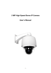
Economic Series Intelligent High Speed Dome Camera User’s Manual CONTENTS BRIEF ITRODUCTION ........................................................................................................................ 2 CHAPTER 1 INTRODUCTION ........................................................................................................... 4 1.1INTRODUCTION ................................................................................................................................ 4 1.2 PICTURES ........................................................................................................................................ 4 1.3 FEATURES ........................................................................................................................................ 5 CHAPTER 2 INSTALLATION AND CONNECTION ....................................................................... 6 2.1 OPTIONAL PARTS FOR INSTALLATION ............................................................................................... 6 2.2 WARNING ........................................................................................................................................ 6 2.3 PREPARATION .................................................................................................................................. 6 2.4 INSTALLATION ................................................................................................................................. 7 2.5 INITIAL SETTING ............................................................................................................................ 10 CHAPTER 3 SETUPS ......................................................................................................................... 14 3.1 HOW TO USE THE KEYBOARD CONTROLLER ................................................................................... 14 3.2 SELF-CHECKING INFORMATION ..................................................................................................... 14 3.3 OSD MENU TREE .......................................................................................................................... 15 Menu Item Description ........................................................................................................... 16 LANGUAGE .......................................................................................................................... 17 SYSTEM INFORMATION .................................................................................................... 17 DISPLAY SETUP ................................................................................................................... 18 DOME SETTING ................................................................................................................... 19 CAMERA ............................................................................................................................... 24 MOTION................................................................................................................................. 26 RESTART ............................................................................................................................... 31 FACTORY DEFAULTS .......................................................................................................... 32 Help and Exit .......................................................................................................................... 32 APPENDIX ........................................................................................................................................... 33 APPENDIX 1:LIGHTNING AND SURGE PROTECTION ........................................................................... 33 APPENDIX 2:RS485 GENERAL KNOWLEDGE .................................................................................... 34 1 BRIEF ITRODUCTION Notice Do not dismantle the machine to avoid electric shock Notice:To avoid electric shock, do not remove the dome cover. Users are not capable of fixing any internal components. Only qualified person is allowed to do the repair. This label indicates that there is uninsulated dangerous voltage which has risk of electric shock. This label reminds there are important operating and maintenance instructions. Notes: To prevent fire or damage caused by electric shock, do not put the speed dome into water. To prevent personal injury, the speed dome must be installed on a solid wall or ceiling bracket. Please refer to installation instructions. Please read these instructions before using the speed dome, follow all instructions and pay attention to all the warnings. Warning: 1 Please do not install near any heat sources such as radiators, stoves or other heating device. 2 Please use specified adapters. Use other adapters may cause fire, electric shock or product damage. Wrong power connection may cause fire, electric shock or product damage. 3 Do not destroy the safety effect the polarized or grounding-type plug. Polarized plug has two lugs, and one is wider than the other. Grounding type plug has two ground sheets and a grounding pin. Wide line or grounding-type pin lugs are used to protect personal safety. 4 Do not step on or squeeze the power cord, and please pay special attention to protect plugs, convenience outlets and equipment contact position. 5 Please use the manufacturer's recommended additional equipment or accessories. 6 Prohibition of simultaneous connections of multiple cameras to a single adapter, and capacity overload of the adapter may cause abnormal heat and fire. 7 Power cord should be firmly plugged into a power socket (connection is not secure may 2 cause a fire) 8 The speed dome should be installed firmly on the wall or ceiling. Falling camera may cause personal injury. 9 Do not put the conductor (such as: screwdrivers, coins or metal objects) or a container with full of water on top of the camera. 10 If the speed dome has abnormal smell or smoke, please stop using it, please shut down the power to avoid fire or electric shock. 11 If the product working improperly, please contact the dealer or the nearest service center. Do not disassemble or in any way to change the product. (Problem caused by disassemble or repair from unauthorized user are not covered in warranty) 12 please clean the machine with a dry cloth and do not splash water directly on the product. 13 Do not put the product opposite the air flow position. Otherwise, the temperature difference between inside and outside will cause moisture condensation on it. 14 When the speed dome installed in cold area (such as cold storage room), please make sure it is sealed with silicone wire leads to prevent outside air come into it. Otherwise, high humidity air outside may flow into the machine case, and internal and external temperature differences cause the product to moisture or water vapor inside. 15 Do not drop objects on the product or hit the product. Keep it away from vibration or magnetic interference. 16 Do not install the product at places with high temperature (over 50 ° C), low temperature (below -50 ° C), or high humidity. 17 When moving the product assembled, please make sure to turn off the power. 18 Do not keep the camera watching at the sun, otherwise it will damage the CCD sensor. 19 After stored in high humidity environments, there may have moisture inside the dome cover. Please clean with soft and dry cloth before reuse. 20 Please use the products in the working environment requirement: Power supply AC24V/2.0A Communication Interface Ambient temperature Environment Humidity Atmospheric pressure RS-485 -35Ԩ~55Ԩ <95% 86~106KPa 3 Chapter 1 Introduction 1.1 Introduction E series speed dome is a strong tool to improve your security effect. It has the highest speed in the market: 0.05~600°/s to catch any target objects, with elevation angle of -8°and auto flip to ensure all outdoor monitoring area. 220 presets, 8 auto scanning, 8 cruising tracks and 4 pattern tours, which meet all the security running operation requirements. The soft address function will give you a new experience for address setting, which will save a lot of time. Remote update function will provide you quick response in maintainance job. 1.2 Pictures Wall-mount Installation In-ceiling Mount Installation 4 1.3 Features OSD Menu Display the speed dome information and status, setting for speed dome functions and features. Soft Address With Soft address function, users do not have to set on the speed dome dip switch and remember those complicate octal address. It can be set in OSD menu from keyboard or PC software which make setup job easy and efficient. Focus/Rotation speed auto match Support automatically adjusts PTZ’s horizontal and vertical speed according to the focus close/far, which will make it easier for manual subject tracking. Dome address setup Support 255 camera hardware address. Set and call preset position Preset position is to store the present PTZ horizontal angle, vertical angle and camera focus, which enable the speed dome go back to the memorized position quickly when needed. Use DVR or keyboard to call preset positions and there are 220 preset positions available. Auto Scan The speed dome will run between set left and right border, watching on a specified area. The speed dome supports 8 auto scan. Auto Cruising The speed dome support 8 cruising tracks, each cruising has max 32 preset positions. It enables the speed dome to switch between different preset position to have quick views on different areas. Pattern Tour (PATTERN) Pattern tour function is to record all the running operation of the speed dome in a time section, including Pan/Tilt running, zooming and focus. The speed dome support 4 group Pattern tours and each has up to 60 seconds record. Privacy Mask Draw a black shield on the screen to protect confidential area in monitoring. Guard Location Function With Guard Location function, the speed dome will go back to set preset position after a period of vacancy. Vacancy time is adjustable for users. Running Direction Display Set Ture North direction to display the rotating direction of the speed dome accurately. Set area indication, when speed dome run to special area, it will show the area title on screen. Password Protection Function To secure speed dome setting from authorized users. Note: Camera is not able to focus clearly in following cases: Target object is not at the middle of the image; Watching at two objects at the same time, one near and the other is far away, camera is not able to focus on both objects; Target object with high light; Target object move too fast; Target object is dark or fuzzy; Target object behind unclear glass. 5 Chapter 2 Installation and Connection 2.1 Optional parts for installation Pedant mount bracket(TC-DF12)for ceiling mounting Pedant mount bracket 2.2 Warning 1 Make sure the installation place is able to afford 4 times weight of the speed dome. 2 Power supply is AC220V, make sure the grounding is correct and do not take live action. 2.3 Preparation 1. Fix the drill position sticker on wall, drill 4 holes according to the indication on the sticker and then install the expansion bolts. 6 2. Please prepare the necessary tools according to specific situations. 2.4 Installation 1. Get the foam out of the carton. Note:Please protect camera and dome base, make sure the foam is removed from the carton vertically and slowly, otherwise it may lead to damage on camera. 2. Please refer to chapter 2.5<Initial Settings> for Dip Switch Settings. 3. Point the gap at the waist-hole, and then use a cross screwdriver to install two stainless steel screws M4 × 6. 7 Note: Please protect the transparent cover. 4. Thread the power cable, video cable,RS-485data cable through the bracket, fix the speed dome with bracket, and tighten 3 internal hexagon screws. 5. Cable Connection 8 6. Put the cables (including power, video cable, RS 485 and ground line) through the bracket. Then fix the speed dome base and the bracket with 4 screws and lock with ¢8 plain cushion and nut. Note: The speed dome must be fully tighten, otherwise it may fall down and cause personal injury. For outdoor use, please pay attention on veneer cracks and cable hole sealing to ensure waterproof. 9 Size of wall mount: Size of in-ceiling mount: Note: The thickness of ceiling should be between 4.2cm to 0.8cm.And the ceiling should support 20kg within 225mm diameter. 2.5 Initial Setting Address Setting E series speed dome support protocol self-adaptation function, it is no need to set the protocol dip switch. Please make sure the 8th bit of SW2 is set to “1” in all cases. Use SW1 to set speed dome address. Address setting adopts binary system, the 8th bit is the highest, the 1st bit is the lowest. Total 255 dome addresses could be set. 10 Note: 1. Put the dial to “ON”, and “1” means “on” status and “0” means “off” status. 2. Dip switch for protocol PELCO-P supports maximum 255 dome addresses; protocol PELCO-D supports maximum 254 dome addresses. 3. Protocol setting The speed dome support protocols: PELCO-P and PELCO-D, and 3 baud rate: 9600BPS, 4800BPS, 2400BPS. Protocol dip switch is bit 1~3 of SW2. 1 2 3 4 5 7 8 ON OFF Agreement 1 bit 2 bit 3 bit TIANDY 0 0 0 PELCO-P 1 0 0 PELCO-D 0 1 0 Reserved …… …… …… *Notice: The factory default protocol is PELCO_D Baud Rate Setting Baud rate setting dip switch is bit 4~5 of SW2, and factory default is 2400bps. 1 2 3 4 5 7 8 ON OFF Baud Rate 4bit 5bit 9600bps 0 0 4800bps 1 0 2400bps 0 1 Preset 1 1 11 Dome address code table under protocol TIANDY/PELCO-P: Address PIN1 PIN2 PIN3 PIN4 PIN5 PIN6 PIN7 PIN8 1 0 0 0 0 0 0 0 0 2 1 0 0 0 0 0 0 0 3 0 1 0 0 0 0 0 0 4 1 1 0 0 0 0 0 0 5 0 0 1 0 0 0 0 0 6 1 0 1 0 0 0 0 0 7 0 1 1 0 0 0 0 0 8 1 1 1 0 0 0 0 0 9 0 0 0 1 0 0 0 0 10 1 0 0 1 0 0 0 0 11 0 1 0 1 0 0 0 0 12 1 1 0 1 0 0 0 0 13 0 0 1 1 0 0 0 0 14 1 0 1 1 0 0 0 0 15 0 1 1 1 0 0 0 0 16 1 1 1 1 0 0 0 0 17 0 0 0 0 1 0 0 0 18 1 0 0 0 1 0 0 0 19 0 1 0 0 1 0 0 0 20 1 1 0 0 1 0 0 0 21 0 0 1 0 1 0 0 0 22 1 0 1 0 1 0 0 0 23 0 1 1 0 1 0 0 0 24 1 1 1 0 1 0 0 0 25 0 0 0 1 1 0 0 0 26 1 0 0 1 1 0 0 0 27 0 1 0 1 1 0 0 0 28 1 1 0 1 1 0 0 0 29 0 0 1 1 1 0 0 0 30 1 0 1 1 1 0 0 0 31 0 1 1 1 1 0 0 0 32 1 1 1 1 1 0 0 0 … … … … … … … … … 254 1 0 1 1 1 1 1 1 255 0 1 1 1 1 1 1 1 12 Comparison chart of the PELCO-D protocol address. Address PIN1 PIN2 PIN3 PIN4 PIN5 PIN6 PIN7 PIN8 1 1 0 0 0 0 0 0 0 2 0 1 0 0 0 0 0 0 3 1 1 0 0 0 0 0 0 4 0 0 1 0 0 0 0 0 5 1 0 1 0 0 0 0 0 6 0 1 1 0 0 0 0 0 7 1 1 1 0 0 0 0 0 8 0 0 0 1 0 0 0 0 9 1 0 0 1 0 0 0 0 10 0 1 0 1 0 0 0 0 11 1 1 0 1 0 0 0 0 12 0 0 1 1 0 0 0 0 13 1 0 1 1 0 0 0 0 14 0 1 1 1 0 0 0 0 15 1 1 1 1 0 0 0 0 16 0 0 0 0 1 0 0 0 17 1 0 0 0 1 0 0 0 18 0 1 0 0 1 0 0 0 19 1 1 0 0 1 0 0 0 20 0 0 1 0 1 0 0 0 21 1 0 1 0 1 0 0 0 22 0 1 1 0 1 0 0 0 23 1 1 1 0 1 0 0 0 24 0 0 0 1 1 0 0 0 25 1 0 0 1 1 0 0 0 26 0 1 0 1 1 0 0 0 27 1 1 0 1 1 0 0 0 28 0 0 1 1 1 0 0 0 29 1 0 1 1 1 0 0 0 30 0 1 1 1 1 0 0 0 31 1 1 1 1 1 0 0 0 32 0 0 0 0 0 1 0 0 … … … … … … … … … 253 1 0 1 1 1 1 1 1 254 0 1 1 1 1 1 1 1 13 Chapter 3 Setups Connect the speed dome to control device (keyboard controller/DVR) or software to adjust setting. 3.1 How to use the keyboard controller Follow the steps below to do the setting: 1 Call the preset position No.95, open the speed dome OSD. 2 Use the joystick to set in the menu. 3 Press to open the menu. 4 Use the joystick to change chosen parameters. 5 Press to save all the changes on setting. 3.2 Self-Checking Information The speed dome camera will launch self-checking operation after power on. It will do horizontal movement first, then vertical movement and finally camera block operations. The starting up image will show self-checking result information on the screen and last for 30 seconds. Horizontal Movement: The speed dome camera rotate in counterclockwise direction to the 0° position, then continuous to go to the original position before power on. Vertical Movement: The speed dome camera moves downwards to 90° position of the horizontal direction, then go upwards to the original vertical position before power on. Camera Operation: The camera block zoom in to the max distant then go back to the original zooming position. 14 3.3 OSD Menu Tree ( .cur) (. cur) ( .cur) (.c ur) (.c ur) ( .cur) (.cur) ( .cur) ( .cur) 15 Menu Item Description LANGUAGE: English/Chinese optional. SYSTEM INFORMATION: Display system info: Address, Protocol, Baud Rate, Temperature, Video Format. DISPLAY SETUP: Set the overlay characters on screen to show time and position information. DOME SETTING: Standby Operation, Privacy Mask, Clock, Manual Limit, Password, Title, Soft address. CAMERA: Set parameters for camera block. MOTION: Set Preset position, Auto Scan, Cruising Tour, Pattern Tour, Guard, Auto-tracking(special camera block) RESTART: Reboot the speed dome. FACTORY DEFAULTS: Recover to factory default, all setting will be lost! HELP: Display speed dome operation help information. EXIT: Exit speed dome menu. NOTES: The following operations in speed dome menu will be supposed to use keyboard controller. It is similar if users are using DVR or other devices. 16 LANGUAGE There are English/Chinese for selection. Use Command: call+95 to open speed dome menu, move the cursor to <LANGUAGE>, press to enter setting, use the joystick of keyboard to select one language then confirm and exit. SYSTEM INFORMATION (.c ur) (.cur) MAIN MENU ------------------------------------------LANGUAGE : ENGLISH <SYSTEM INFORMATION> <DISPLAY SETUP> <DOME SETTINGS> <CAMERA> <MOTION> RESTART FACTORY DEFAULTS HELP EXIT SYSTEM INFORMATION ------------------------------------------DOME ID : 001 ADDRESS : 011 BAUDRATE:9600, N, 8,1 PROTOCOL :PELCO P <OTHERS> A B C D BACK EXIT A: DOME ID B: ADDRESS C: BAUDRATE D: PROTOCOL <OTHERS> (.c ur) SYSTEM INFORMATION ------------------------------------------DOME ID : 001 ADDRESS : 011 BAUDRATE:9600, N, 8,1 PROTOCOL :PELCO P <OTHERS> OTHERS ------------------------------------------TITLE : TITLE VERSION: V36201 <SET UPBACK> A B C BACK EXIT (.cur) BACK EXIT A:TITLE B:VERSION C:<SET UPBACK> The function is designed for external EEP storage. If external EEP is failed, the program will use backup information to keep the speed dome working properly. Press ”OK” to backup. It will not affect normal use of the speed dome. 17 (.cur) (.c ur) DISPLAY SETUP (.cur) (.cur) MAIN MENU ------------------------------------------LANGUAGE : ENGLISH <SYSTEM INFORMATION> <DISPLAY SETUP> <DOME SETTINGS> <CAMERA> <MOTION> RESTART FACTORY DEFAULTS HELP EXIT DISPLAY SETUP ------------------------------------------DOME : ON PRESETS : 5 SEC MOTION :5 SEC ZONES : ON PAN/TILT: ON ADDR/PRO/BAUD: ON <DISPLAY POSITION> BACK EXIT A: DOME On/off B: PRESETS Off/on /2 seconds/5seconds/10seconds C:MOTION Off/on/2 seconds/5seconds/10seconds D: ZONES Off/on/2 seconds/5seconds/10seconds E: PAN/TILT Off/on/2 seconds/5seconds/10seconds F: ADDR/PRO/BAUD On/off. (address/protocol/baudrate) G:<DISPLAY POSITION > 18 A B C D E F G DISPLAY POSITION ------------------------------------------<DOME TITLE> <ZONES> <MOTION> <PAN/TILT> (.cur) (.cur) DISPLAY SETUP ------------------------------------------DOME : ON PRESETS : 5 SEC MOTION :5 SEC ZONES : ON PAN/TILT: ON ADDR/PRO/BAUD: ON <DISPLAY POSITION> A B C D BACK EXIT BACK EXIT A: DOME TITLE Use the joystick of the keyboard to move the “dome title: to the specified position on screen. B: ZONES Use the joystick of the keyboard to move the “area information” to the specified position on screen. C: MOTION Use the joystick of the keyboard to move the “Auto Function Title” to the specified position on screen. D: PAN/TILT Use the joystick of the keyboard to move the “Coordinate Indication” to the specified position on screen. DOME SETTING (.cur) MAIN MENU ------------------------------------------LANGUAGE:ENGLISH <SYSTEM INFORMATION> <DISPLAY SETUP> <DOME SETTINGS> <CAMERA> <MOTION> RESTART FACTORY DEFAULTS (.cur) (.cur) DOME SETTINGS ------------------------------------------<IDLE> <PRIVACY MASK> <PASSWORD> <DOME TITLE> <OTHERS> A B C D E BACK EXIT BACK EXIT 19 A. IDLE (.cur) ( .cur) IDLE ACTION ------------------------------------------TIME :30SEC ACTION:NONE DOME SETTINGS ------------------------------------------<IDLE> <PRIVACY MASK> <PASSWORD> <DOME TITLE> <OTHERS> A1 B1 BACK EXIT BACK EXIT A1:TIME Move the cursor to “Time” to set the idle action launching time. 30seconds/1 minute/5 minutes/10 minutes/30 minutes in the menu for selection, press to confirm. B1: ACTION Move the cursor to “ACTION” to set the idle actions: Preset position/Scan/sequence/Pattern/ None. B. PRIVACY MASK (.cur) (.cur) PRIVACY MASK ------------------------------------------MASK NO :1 ENABLE :OFF <SET> DELETE DOME SETTINGS ------------------------------------------<IDLE> <PRIVACY MASK> <PASSWORD> <DOME TITLE> <OTHERS> A1 B1 C1 D1 BACK EXIT BACK EXIT A1. MASK NO. Move the cursor to “MASK NO.” to set the number of privacy mask zone. B1.ENABLE Enable/Disable. C1. <SET> To set the position on the screen of the privacy mask. Use joystick to move the mask square to the specified position. D1. DELETE Press to delete the current privacy zone. 20 (.cur) (.cur) PRIVACY MASK ------------------------------------------PRIVACY MASK:1 ENABLE :OFF <SET> DELETE WARNING ------------------------------------------MASK DELETE … OK CANCEL BACK EXIT C. PASSWORD (.cur) (.cur) DOME SETTINGS ------------------------------------------<IDLE> <PRIVACY MASK> <PASSWORD> <DOME TITLE> <OTHERS> PASSWORD ------------------------------------------<EDIT PASSWORD> ENABLE:OFF BACK EXIT BACK EXIT TIPS: left use ‘near’, right use ‘far’ A1.EDIT PASSWORD The factory default password is 111111. INPUT OLD PASSWORD ------------------------------------------INPUT: _ _ _ _ _ _ NUMBER 0123456789 (.cur) PASSWORD ------------------------------------------<EDIT PASSWORD> ENABLE:OFF (.cur) BACK EXIT OK Tips: left use ‘near’, right use ‘far’ B1.ENABLE Enable/disable the password protection for OSD menu 21 CANCEL A1 B1 D. DOME TITLE DOME SETTINGS ------------------------------------------<IDLE> <PRIVACY MASK> <PASSWORD> <DOME TITLE> <OTHERS> (.cur) (.cur) DOME TITLE SET ------------------------------------------INPUT: _ _ _ _ _ _ _ _ <CAPS> A B C D E F G H I J K L M N O P Q R S T U V W X Y Z TIPS: left use ‘near’, right use ‘far’ BACK EXIT OK OK DOME TITLE SET ------------------------------------------INPUT: _ _ _ _ _ _ _ _ <CHINESE> A B C D E F G H I J K L M N O P Q R S T U V W X Y Z ↑↓← […………] [……………………………] (.c ur) (.c ur) DOME TITLE SET ------------------------------------------INPUT: _ _ _ _ _ _ _ _ <SMALL> a b c d e f g h i j k l m n o p q r s t u v w x y z . ← CNACEL CANCEL OK CANCEL (.cur) (.c ur) DOME TITLE SET ------------------------------------------INPUT: _ _ _ _ _ _ _ _ <NUMBER> 0 1 2 3 4 5 6 7 8 9 OK CNACEL DOME TITLE SET ------------------------------------------INPUT: _ _ _ _ _ _ _ _ <SYMBOL> , 。 : ! ? ¥ * ( ) : @ # % 《 》 - + & [ ] OK CANCEL A1. INPUT Move the cursor to INPUT and press to enter the title setting mode. B1. < CAPS> Press and move the joystick upward and downward to select capital or lower letters. C1. ALPHABET Move the cursor to alphabet and press to select letters. D1. OK/Cancel 22 A1 B1 C1 D1 H. OTHERS DOME SETTINGS ------------------------------------------<IDLE> <PRIVACY MASK> <PASSWORD> <DOME TITLE> <OTHERS> (.cur ) (.cur) OTHERS ------------------------------------------AUTO FLIP :ON AUTO STOP TIME :15SEC MENU OFF TIME :5M TILT ANGLE SET :-5 SPEED LEVEL :HIGH <NORTH SET> <ADDRESS SET> BACK EXIT A1 B1 C1 D1 E1 F1 G1 BACK EXIT A1:AUTO FLIP The speed dome will rotate 180°in horizontal direction after 2 seconds if it moves to 90°in the vertical direction. Choose “Open/Close” in the menu to enable/disable the function. B1:AUTO STOP TIME Set the stop time for speed dome when there is no stop command, 5 seconds/15 seconds/ 30 seconds/ 60 seconds for selection. C1:MENU OFF TIME Automatically close the menu, 1 minute/2 minutes/ 5 minutes/10 minutes for selection. D1. TILT ANGLE SET Default angle is -3°, the adjust range is from 0°~ -8°. E1. SPEED LEVEL High/Mid/Low. F1. <NORTH SET> Set the ture north direction for the speed dome. Enter the menu and use the joystick of keyboard to move the speed dome to the ture north direction in horizontal direction, and then confirm to set. G1. < ADDRESS SET> OTHERS ------------------------------------------AUTO FLIP :ON AUTO STOP TIME :15SEC MENU OFF TIME :5M TILT ANGLE SET :-5 SPEED LEVEL :HIGH <NORTH SET> <ADDRESS SET> ADDRESS SET ------------------------------------------HARD ADDRESS: 001 SOFT ADDRESS : 001 <EDIT SOFT ADDRESS> SOFT ADDRESS : OFF (.cur ) BACK EXIT BACK EXIT 1. Hardware address has to be set in dip switch on the speed dome board. 2. Software address is a new function for easy address setup, it is recommended to use it for installation. 3. Edit soft dip switch 23 INPUT SOFT ADDRESS ------------------------------------------INPUT:<- _ _ NUMBER 0123456789 (.cur ) ADDRESS SET ------------------------------------------HARD ADDRESS: 001 SOFT ADDRESS : 001 <EDIT SOFT ADDRESS> SOFT ADDRESS : OFF TIPS:IF PELCO P, ADDRESS=SET VALUE+1; IF PELCO D,ADDRESS= SET VALUE. SETVALUE FROM 0 TO 254. BACK EXIT OK CANCEL <1> Input address in 3 bits <2> Tiandy/Pelco_P address range: 1~255, Pelco_D address range: 1~254 <3> Reboot the speed dome after setting to enable the software address function. CAMERA (.cur ) (.cur ) MAIN MENU ------------------------------------------LANGUAGE: ENGLISH <SYSTEM INFORMATION> <DISPLAY SETUP> <DOME SETTINGS> <CAMERA> <MOTION> RESTART FACTORY DEFAULTS HELP EXIT CAMERA SETTING ------------------------------------------AUTO FOCUS : ON DIGITAL ZOOM: ON BACKLIGHT : ON FREEZE : ON ZOOM SPEED : LOW DAY NIGHT : AUTO IMAGE : ON <ADVANCED> A B C D E F G H BACK EXIT The speed dome integrate Sony camera block OSD into the speed dome OSD, for other brands of camera block, it will call up its own OSD menu for setting. A. AUTO FOCUS Switch Auto/ML/trigger function. B.DIGITAL ZOOM On/off C.BACKLIGHT When the light is dim, please open the backlight compensation to make the image bright D.FREEZE On/off E.ZOOM SPEED: LOW/NORMAL/HIGH 24 F: DAY/NIGHT Auto/BW/Color G: IMAGE On/off H. <ADVANCED> (.cur) CAMERA SETTING ------------------------------------------AUTO FOCUS : ON DIGITAL ZOOM: ON BACKLIGHT : ON FREEZE : ON ZOOM SPEED : LOW DAY NIGHT : AUTO IMAGE : ON <ADVANCED> (.c ur) (.cur) BACK EXIT ADVANCED ------------------------------------------WB : AUTO RED GAIN : 208 BLUE GAIN : 167 EXPOSURE : AUTO SHUTTER : 1/50 WIDE DYNAMIC : ON SSNR : OFF STABILIZER : OPEN A1 B1 C1 D1 E1 F1 G1 H1 BACK EXIT A1. WB AUTO/MANUAL/ATW/INDOOR/OUTDOOR B1. RED GAIN 0-255 C1. BLUE GAIN 0-255 D1.EXPOSURE Auto/iris/shut/menu Choose “shut” to adjust shutter parameter; choose “iris” to adjust Iris parameter; choose “manu” to set both shutter and iris, shutter and iris parameters are as below: Shutter:1/2 1/6 1/12 1/50 1/100 1/600 1/1000 1/10000 Iris:F1.6 F2.4 F4.0 F6.0 F8.0 F14.0 E1: SHUTTER 1/2 1/6 1/12 1/50 1/100 1/600 1/1000 1/10000 F1: WIDE DYNAMIC ON/OFF *NOTICE: This item is only for the camera module with WDR function. 25 G1: SSNR off/low/mid/high H1: STABILIZER Off/open/hold MOTION (.cur) (.c ur) MAIN MENU ------------------------------------------LANGUAGE: ENGLISH <SYSTEM INFORMATION> <DISPLAY SETUP> <DOME SETTINGS> <CAMERA> <MOTION> RESTART FACTORY DEFAULTS HELP EXIT MOTION ------------------------------------------<PRESET> <SCAN> <SEQUENCE> <PATTERN> <ZONES> A B C D E BACK EXIT A.PRESET (.cur ) ( .cur) MOTION ------------------------------------------<PRESET> <SCAN> <SEQUENCE> <PATTERN> <ZONES> PRESET ------------------------------------------ PRESET NO:001 TITLE :PRESET CALL <SET> DELETE BACK EXIT 01 A1 B1 C1 D1 E1 BACK EXIT A1: PRESET NO Move the cursor to <Preset Position Number>, press to select preset number. The dome cameras support 220 preset positions. B1: TITLE Move the cursor to <Title Setup>, press to enter the sub-menu of title setup for the preset positions. C1: CALL Move the cursor to <Call>, press to call the corresponding preset positions. D1: <SET> Press to enter setting mode, when “Press the icon to confirm” shown on the screen, it is available to operate the camera, then press to save the new position. 26 E1:DELETE Move the cursor to “Delete”, press the icon of “Iris On” to delete the set preset positions. B. SCAN (.cur ) (.cur) (.cur ) MOTION ------------------------------------------<PRESET> <SCAN> <SEQUENCE> <PATTERN> <ZONES> BACK EXIT SCAN ------------------------------------------SCAN NO.:1 TITLE :SCAN 1 START <LEFT LIMIT> <RIGHT LIMIT> SCAN SPEED:20 A1 B1 C1 D1 E1 F1 BACK EXIT A1. SCAN NO. Move the cursor to <SCAN NO>. to enter the setting mode of “scan No.”, use the joystick of keyboard to select digit number. Then confirm and exit. Each speed dome supports 8 scan paths.. B1. TITLE Move the cursor to <TITLE> to enter the setting mode of sub-menu for title setting of scan path. (.cur ) (.cur) (.cur ) SCAN ------------------------------------------SCAN NO.:1 TITLE :SCAN 1 START <LEFT LIMIT> <RIGHT LIMIT> SCAN SPEED:20 AUTO SCAN TITLE SET ------------------------------------------INPUT: _ _ _ _ _ _ _ _ CAPS A B C D E F G H I J K L M N O P Q R S T U V W X Y Z OK BACK EXIT CANCEL C1.START Move the cursor to <START> to start the current scan. D1. <LEFT LIMIT> Move the cursor to <LEFT LIMIT> and confirm to start setting the left margin of the current scan. Then “PRESS TO CONFIRM” will appear on the screen. Move the joystick and press to confirm. E1. <RIGHT LIMIT> Move the cursor to <RIGHT LIMIT> and press confirm to start setting the right margin of the current scan. Then “PRESS TO CONFIRM” will appear on the screen. Move the joystick to press confirm. F1. SCAN SPEED Move the cursor to <SCAN SPEED> and press to enter the setting mode of scan speed. Move the joystick upward and downward to select the speed scale, press to confirm. The speed scale ranges is between 1~30. C. SEQUENCE 27 (.c ur ) (.cur ) SEQUENCE ------------------------------------------SEQ NO. :1 TITLE :SEQ 1 START <SEQUENCE SET> DELETE MOTION ------------------------------------------<PRESET> <SCAN> <SEQUENCE> <PATTERN> <ZONES> BACK EXIT A1 B1 C1 D1 E1 BACK EXIT A1. SEQ NO. Move the cursor to <SEQ NO.> and press to enter the setting mode of “Sequence No.”, move the joystick upward and downward to select number. Then press to confirm. B1. TITLE Move the cursor to <TITLE> and press to enter the setting mode of sequence title. C1.START MOVE the cursor to <START> and press to start the current sequence. D1. <SEQUENCE SET> Press to enter the sequence setting (.cur) (.cur) Move the cursor to <SEQUENCE SET> and press to enter <EDIT> mode. Move the joystick rightward or leftward to select item. a. When the icon of “ < >” is on the item NO., move joystick upward or downward to select one preset position for a sequence. One single sequence supports 32 presets. b. When the icon of “< >” is on the item “PRESET”, move the joystick upward or downward to select a specified preset to add in the sequence. “INTERVAL” is the time interval between two presets in one sequence. c. When the icon of “< >” is on the item: “INS”, move the joystick upward or downward to select setting mode as “insert”, “ok” and “delete”. d. Move the cursor to “BACK” or ”EXIT” and press to quit the setting. E1:DELETE Move the cursor to <DELETE> and press to delete the current sequence. 28 SEQUENCE ------------------------------------------SEQ NO. :1 TITLE :SEQ 1 START <SEQUENCE SET> DELETE (.cur) WARNING ------------------------------------------ARE YOU SURE … (.cur) OK CANCEL BACK EXIT D. PATTERN (.cur) ( .cur) (.cur) MOTION ------------------------------------------<PRESET> <SCAN> <SEQUENCE> <PATTERN> <ZONES> BACK EXIT PATTERN ------------------------------------------PATTERN NO. :1 TITLE :PATTERN 1 START <SET> DELETE A1 B1 C1 D1 E1 BACK EXIT A1.PATTERN NO. Move the cursor to <PATTERN NO.> and press to enter the setting mode of pattern number, move the joystick upward or downward to select number, then press to confirm. B1. TITLE Move the cursor to <TITLE> and press to enter the setting mode of PATTEN title. C1.START MOVE the cursor to <START> and press to start the current Pattern. D1. <SET> Move the cursor to <SET> and press to enter pattern setting mode. Then “PRESS IRIS ON TO CONFIRM” will appear on the screen. Use the keyboard to do PTZ operation and press to confirm. 29 (.cur) ( .cur) (.cur) PATTERN ------------------------------------------PATTERN NO. :1 TITLE :PATTERN 1 START <SET> DELETE PATTERN RECORDING ------------------------------------------- REMAIN:180 SEC IRIS OPEN TO CONFIRM BACK EXIT BACK EXIT E1.DELETE Move the cursor to <DELETE> and press to delete the current pattern. PATTERN ------------------------------------------PATTERN NO. :1 TITLE :PATTERN 1 START <SET> DELETE (.cur) WARNING ------------------------------------------ARE YOU SURE … (.cur) OK CANCEL BACK EXIT E.ZONES (.cur) (.cur) (.cur) MOTION ------------------------------------------<PRESET> <SCAN> <SEQUENCE> <PATTERN> <ZONES> BACK EXIT ZONES -------------------------------------------- ZONE IS NOT SET -ZONE NO. :1 TITLE :ZONE1 <LEFT LIMIT> <RIGHT LIMIT> DELETE A1 B1 C1 D1 E1 F1 BACK EXIT A1. ZONE INFORMATION Show the status of zone. Zones function is used to show zone information when the speed dome run to the preset zone area. B1. ZONE NO. Move the cursor to <ZONE NO.> and press to enter the setting mode of zone number, move the joystick upward or downward to select number, then press to confirm. C1. TITLE Move the cursor to <TITLE> and press to enter the setting mode of zone title. 30 D1. <LEFT LIMIT> Move the cursor to <LEFT LIMIT> and press to start setting the left margin of the current zone. Then “PRESS IRIS ON TO CONFIRM” will appear on the screen. Use the joystick to press confirm. E1. <RIGHT LIMIT> Move the cursor to <RIGHT LIMIT> and press to start setting the left margin of the current zone. Then “PRESS IRIS ON TO CONFIRM” will appear on the screen. Use the joystick to press confirm. F1.DELETE Press to delete the current zone. ZONES -------------------------------------------- ZONE IS NOT SET -ZONE NO. :1 TITLE :ZONE1 <LEFT LIMIT> <RIGHT LIMIT> DELETE (.cur) WARNING ------------------------------------------ARE YOU SURE … (.cur) OK BACK EXIT RESTART ( .cur) Press to reboot the speed dome camera. 31 CANCEL FACTORY DEFAULTS ( .cur) Press to recover all the settings to the factory default. Help and Exit (.cur) MAIN MENU ------------------------------------------LANGUAGE: ENGLISH <SYSTEM INFOMATION> <DISPLAY SETUP> <DOME SETTINGS> <CAMERA> <MOTION> RESTART FACTORY DEFAULT HELP EXIT MENU OPERATION HELP ------------------------------------------1. CALL PRESET 95 TO OPEN MENU. 2. MOVE JOYSTICK TO SELECT MENU ITEM. 3. IRIS OPEN TO ENTER EDIT MODE. 4. MOVE JOYSTICK TO EDIT PARAMETER. 5. IRIS OPEN CONFIRM. (.cu r) BACK EXIT Click to get the help information of shortcut. Move the cursor to “Exit”, press to exit from the menu. Remark: 1. The camera block, such as Sony, LG, Samsung has their own OSD. To its own OSD, please click the “Exit” of the OSD or use command: “call+ 96” to exit the OSD menu. Command: call+96 is unavailable for Samsung camera block. 2.To support shortcuts, the operation mode of joystick will be changed, right direction means “confirm”, left direction means ”cancel”. “Focus near” and “Focus Far” on the keyboard indicate the left and right shifting on menu. 32 Appendix Appendix 1:Lightning and surge protection The outdoor speed dome need to have the function of lightning and surge protection, in order to make sure that electronic components are safe, please take the following measures: The transmission cable must be keep 50 meters away from the high-tension apparatus and high-voltage cable; It’s better to arrange the outside cable under the eave; In the open area, the wire must be sealed by the steel tube, and connect the earth by one end, the way of overhead wire arrangement is forbidden; In the strong lightening storm or high voltage areas, the extra high-power lightening protection device and lightning rod are needed. The design of lightning protection must be matched with the building’s lightning protection requirement and it needs to correspond requirement of the country and/or industry standard. The system must connect to the earth at ISO-Electrical level. The earth connection device must meet the requirement of anti-interference and electrical safety and can’t be short circuit or hybrid junction with the strong current. When the system connects the earth, the resistance is no more than 4Ω, the cross sectional area is no less than 25mm2. The resistance of Video Lightning arrester, Communication Lightning arrester, Power Lightning arrester and Earth conductor is no more than 4Ω, Steel jacket, Lightning arrester, Speed dome must be installed under the lightning arrester within 45 degrees. 33 Appendix 2:RS485 General Knowledge 1. RS485 Basic Features According to the RS485 industry standard, the resistance is 120Ω, the maximal load capacity is 32 valid loads. 2. RS485 transmission distance When using the FTP of 0.56mm (24AWG) as cable, according to the baud rate’s difference, the maximal transmission distance is as following: Baud Rate Max. Distance 2400Bps 1800m 4800Bps 1200m 9600Bps 800m When the cable is thin or EMI is strong or the there are too many other devices, the transmission distance will be shorten. 3. Connection and terminal resistance When arranging the wires, the way of connection use the way of snakelike, both of the ends must connect 120Ω terminal resistance, the simple connection is as the Chart 7, the distance is no longer than 7 meters. ..... 120Ω 1# 2# 3# 4# 120Ω 32# Picture 2 A+ . . . . . BD A+ B. . . . . 120Ω Controller 1# 2# 3# 120Ω 31# Picture 3 4. Problems in the practical application In the practical application, most of the clients use the star-type as a connection mode, however the terminal resistance must connect the two devices in a longest distance, such as 1# and 15#, as this kind of connection doesn’t meet the requirement of RS485 industry standard, it will cause the problems of signal reflex, weaken the ability of anti-interference and signal control. In this case, the RS485 divider is recommended, it can change the star-type to a new connection that can meet RS485 industry standard and improve the reliability of communication. 34 Picture 4 Picture 5 RS485 common faults solution Phenomenon Possible reason Solution 1.Host machine, speed dome’s address and 1.Change the host machine, speed dome’s address baud rate is not matching and baud rate to be the same self-checking, but can’t be 2.RS485’s+.- pole is reversed 2.Conversion the +.- pole controlled 3.Cable loosen 3.Fasten the cable 4.RS485 is damaged 4.Use a new RS485 cable 1.RS485’s contact is poor 1.Reconnect the RS485 cable 2.One RS485 is damaged 2.Use a new RS485 cable 3.The distance between host machine and 3.Install terminal resistance Speed Speed dome dome controlled well can can’t take be speed dome is too far 4.Too many speed domes 4.Install RS485 divider 35