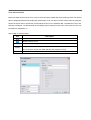
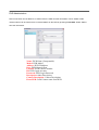
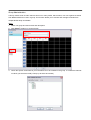
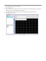
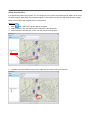
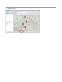
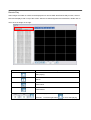
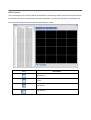
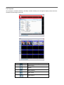
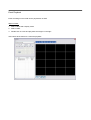
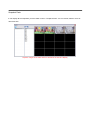
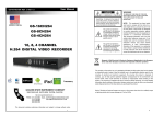
1
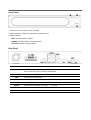
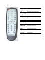
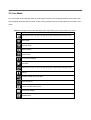
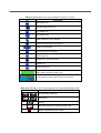
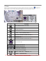
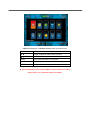
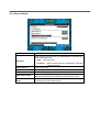
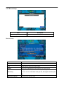
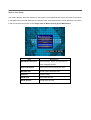
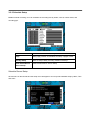
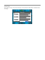
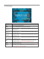
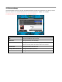
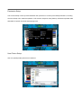
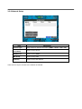
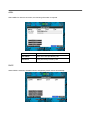
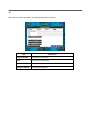
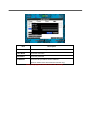
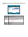
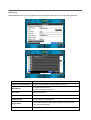
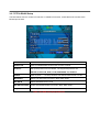
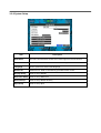
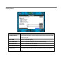
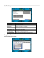
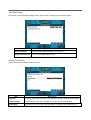
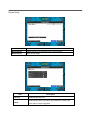
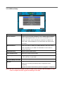
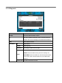
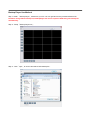
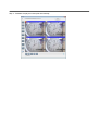
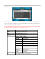
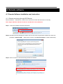
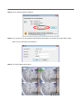
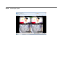
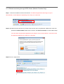
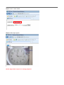
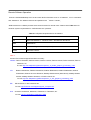
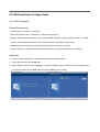
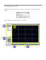
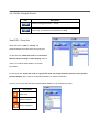
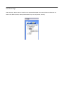
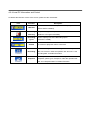
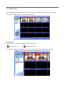
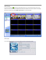
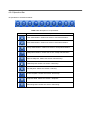
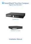
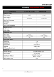
pages from
DVR4rt-H264
User Manual
Hardware Overview
A. Front Panel
B. Rear Panel
C. HDD Installation
Remove top cover of the DVR and install HDD
HDD
D. PTZ connection
www.allthings.com.au
Front Panel
1. IR Sensor: IR receiver for remote controller
2. USB Connectors: USB port connection for USB pen drive.
3. Status Indicator:
RED: Indicates power on status
GREEN: Indicates network connection status
YELLOW: Indicates recording status
Rear Panel
Label
VIDEO IN
Operation
4 connectors for composite video input.
Connect camera output to Video-in (NTSC/PAL)
CRT
Connector for composite video output to Video Monitor, TV, etc.
VGA
Connector for VGA monitor
AUDIO
1 Audio Input and 1 Audio Output
MOUSE
Connection for USB mouse
RS-485
Connect to PTZ camera,+PTZ D+
LAN
RJ45 connector for LAN connection.
DC 12V
Use 12V DC supplied adapter ONLY.
/ - PTZ D-
Remote Controller
Live view function control
REC
To activate Emergency Recording
LOCK
Lock mouse and remote controller operation
4S / 9S
4 split / 9 split display
ZOOM
To enlarge the display. The selected area can be
moved by the direction buttons
PIP
Picture in Picture. Press again to switch in
between PIP mode and full screen mode
STATUS
DVR Status display
0~9 number
Live display channel selection / password entering
MENU/II
Enter setup menu
ESC
Back to menu
ENTER/MODE &
Select or adjust options in setup menu. Navigate
Direction keys
the selected item in setup menu
PLAY
Instant Replay
T-SRH
Open the playback search window
BK/UP
Enter Backup Mode
PTZ
Enter the PTZ camera (speed dome) control mode
IRIS+ / IRIS-
Adjust IRIS Function
ZOOM+/ZOOM-
Adjust ZOOM Function
FOCUS+/FOCUS-
Adjust FOCUS Function
System Overview
3-1. General Usage Information
The STANDARD series DVR can be operated with a mouse or remote controller under the four main modes
listed below:
Live Mode – Allow user to view all live operating cameras and access to Pan/Tilt camera controls.
In
addition, system status information will be shown during live mode.
Setup Mode – Allow user to customize settings for Live viewing, Recording, Backup, and Camera related
devices under the Setup Mode.
Backup Mode – Allow user to archive desired data to a preferred supported media, such as USB Backup,
Remote Client Software, etc.
Search Mode – Allow user to review all recorded footage by using a calendar or event based search.
Password Protection
The DVR unit uses User ID and Password system to prevent unauthorized operation. ( Default settings are
blank for these fields).
IDs and Passwords should be managed by a system administrator ONLY. Different users may be assigned
with different levels authorities to the DVR.
3-2 Live Mode
You can monitor all the channels, listen to audio signal and have some related operations under LIVE mode.
This paragraph describes the IR remote control, mouse operation and on screen graphical icons under LIVE
mode.
Table 3-2.1 Graphical icons that will display after right-clicking your mouse under Live mode.
Icon
Description
Resting the cursor on this icon will bring up the following four menu icons.
Main Menu
Search Setup
Backup Menu
PTZ Control
Turn on/off recording
Playback
Resting the cursor on this icon will bring up the following five display icons.
Pause
ZOOM, double the screen size
Auto Sequence
LOCK, activate the key lock.
Full screen display.
Quad display.
Table 3-2.2 Description of on screen graphical icons in Live mode
Icon
Description
Recording is on
Schedule Recording is on
Live Audio is on
Live Audio is off
Motion detected on the channel
Video loss detected on the channel
USB device detected
Connected to the LAN cable.
AUTO-seq is on
Freeze is on, screen is frozen
LOCK is on
PTZ control is on
Indicate the current used hard disk space
(99% mean used 99%, remain 1%)
Lower right of each CH will show the current time
Table 3-2.3 Description of on screen graphical icons in Remote Software mode
Icon
/
/
Description
Image quality (High/Low)
Full screen
Record
Record and snap shot file saving path setup
Enable / Disable Shortcut Toolbar
PTZ Mode
Switch to the PTZ mode by pressing “PTZ” button under the LIVE mode. The PTZ icon
will appear on
upper left side of screen and the control panel will appear on the down right side of screen.
Icon
Description
Exit PTZ Mode and return to LIVE mode
Pre-set number N. (0~255)
Go to pre-set number N.
Set current PTZ location at pre-set number N.
「TOUR」
, Press to activate pre-set tour. *
Set current PTZ location as the start of line-scan. *
Activate line-scan. *
Set current PTZ location as the end of line-scan. *
To move PTZ in 360°
PTZ zoom in; PTZ zoom out
PTZ focus in; PTZ focus out.
PTZ IRIS open, PTZ IRIS close.
Below functions need support from specific PTZ manufacturer.
Please check user manual of your PTZ for more details.
to
AUX 1~8,「AUTO」Key + Number key「1~8」
「Backup」, Customized function。
* PTZ protocol may varied from different brands and may not be 100% compatible . Therefore,
some of these functions may be unavailable.
3-3 Setup Mode
To enter the main menu and set up DVR, log-in account and user password are required.
The default password of the Administrator account is “123456”. Please check the “Account Setup” for related
setup of other log-in users.
Table 3-3-1 Definition of Virtual Keyboard.
Item
Description
Switch between upper and lower case.
/
Switch between numbers and letters.
Press to cancel the setup.
Delete the last character.
Enter to confirm the password.
Space bar
Table 3-3-2 Operation of Remote Control under the setting menu
Item
Description
Switch to different options under one item
Switch to different items
MENU
Save setup and back to LIVE mode
ESC
Return to previous level of menu without saving
ENTER
Enter the menu, or display virtual keyboard
The initialization of new installed HDD is required before recording.
Please refer to “3-3-9 Utilities Setup” for details.
3-3-1 Record Setup
Item
Description
Select STOP to stop recording or OVERWRITE to overwrite the
HDD when HDD is full
HDD FULL
「Stop」
:Stop Recording
「Overwrite」
:Start overwriting from the oldest data of HDD and
continuing record.
OSD Position X
Setup OSD X axis
OSD Position Y
Setup OSD Y axis
OSD Position Setup
Preview OSD position
Video Preservation
Setup the video preservation period. Recorded video will be
deleted automatically after expiration of preservation period.
Quality & Frame Rate
Setup
Setup the quality and frame rate for each channel under normal
recording and event recording type.
Quality & Frame Rate Setup
Item
Normal Setup/
Event Setup
Resolution
Description
Select recording mode
Select recording resolution: NTSC:360x240, 720x240, 720x480
PAL:360X288,720X288,720X576
Record Type
Setup quality and FPS separately for record type.
No.
Check/uncheck the box to enable/disable selected channel recording
Quality
Select Quality: Below Basic/ Basic/ Normal/ High/ Highest
FPS
Select recording frame rate.
Auto
Assign each channel automatically with its maximum available fps
3-3.2 Event Setup
Item
Description
Enter to set up motion detection
Motion Setup
Motion Setup
Item
Description
Alarm Duration(Seconds)
Setup alarm duration when motion is detected.
1~4
Select desire channel for motion setup.
Enable
Check to Enable/Disable motion detection for each channel.
Drag the white bar or press
Sensitivity
for each channel. The lower value you set, the higher sensitivity will
be.
Motion Area Setup
to set up Sensitivity from value 1 to 10
Setup motion detection area
Motion Area Setup
The motion detection has been divided into 16x12 grids. The default detection area is full screen as it marked
in transparent for local DVR and purple for remote access. Areas deselected for motion detection are marked
in red for both local and remote access. Right click on Mouse to bring up the Menu below.
Item
Mask Mouse Selection
Description
Switch between “select” and “deselect” for
cursor-dragging function
All Area Detection
Select entire screen as detection area.
Mask All Area
Deselect entire detection area.
Continue
Continue setup
Exit & Save
Save setup and exit
Exit & Discard
Cancel setup and exit
3-3-3 Schedule Setup
Besides manual recording, user can schedule the recording time by weeks, normal, motion detect, and
recording type.
Item
Description
Page
Each page provides 10 schedules for setup. 5 pages in total.
Holiday Setup
Enter to setup holiday recording. Maximum 50 days.
View Event/ Motion/
View Normal/ Motion/ Sensor Setup
Sensor Setup
Schedule Record Setup
Click the time on the left side and the setup menu will appears. User may select detailed setup by dates, Time
and event.
Holiday Setup
Since holidays are vary in every country and region, user may setup the holiday based on individual location
accordingly.
3-3-4 Camera Setup
Item
Description
1~4
Setup each channel independently.
Mask
Check to Enable/Disable mask function for LIVE mode
Sharpness
Brightness
Contrast
Chroma(U)/(V)
Hue
Name
Volume
Drag the bar or press
to adjust camera sharpness from value 0 to 15. The
default value is 1.
Drag the bar or press
to adjust camera brightness from value 1 to 255.
The default value is 128.
Drag the bar or press
to adjust camera contrast from value 1 to 255. The
default value is 100.
Drag the bar or press
to adjust camera chrominance from value 1 to 255.
The default value is 128.
Drag the bar or press
to adjust camera hue from value 1 to 255. The
default value is 128. ( PAL system does not support this function).
Set up each channel name.
Adjust audio volume for CH1 under LIVE mode and recording mode.( Only 1
CH can be adjusted in 4CH model series)
3-3-5 Account Setup
The Account Setup menu is to provide role-based permission for each user (maximum of 4 users) to access
DVR over network. The default Administrative account and password is “admin” and “123456”
(The default password remains unchanged after firmware upgrade)
Item
Description
No.
Check to activate the user account.
Username
Set up username ( case sensitive)
Password
Set up password for each user. 8-digits password is required and
can be mixed by letters and numbers with case-sensitive.
Permissions
Set up Permissions for each user
Change Admin Password
Change administrator password
Picture
Change user picture
Permission Setup
The Account Setup is set to provide individual user (maximum of 4 users) role-based permissions, including
access to Setup menu, Network operation, PTZ function, Playback, Utility, Backup, Password expiration date
and Mask on specific channels while playing back.
User Picture Setup
User can upload profile picture from hard drive.
3-3-6 Network Setup
Item
Description
Connect type
Setup mode for network connection: (ADSL、
、DHCP、
、LAN、
、3G).
HTTP Setup
Enter to set up HTTP
DDNS Setup
Enter to set up DDNS
Mail Setup
Enter to set up mail
3G Setup
Enter to set up 3G network
There are four ways to connect to the network as followed.
ADSL
Select ADSL for network connection, the following information is required.
Item
Description
User Name
Enter user name provided by ISP
Password
Enter password provided by ISP
DHCP
When DHCP is selected, IP address will be assigned by DHCP server automatically.
LAN
Select LAN for network connection, the following information is required.
Item
Description
IP Address
Enter IP address provided by ISP
Subnet Mask
Enter IP address of Subnet Mask provided by ISP
Gateway
Enter IP address of Gate way provided by ISP
DNS
Enter DNS address provided by ISP.
(The correct DNS address must be entered for DDNS function).
3G
Select 3G for network connection, the following information is required.
Item
Description
Dial-up Number
Provided by 3G provider
PIN
Enter SIM card password
APN
Vary from 3G providers
Advance Setting
The advanced settings
Item
Description
Enable
Enable advance setting
User Name
Enter ISP username
Password
Enter ISP password
IP Address
Enter the ISP provides a fixed IP address。
(Enter a fixed IP if the client uses the Internet only)
Note:
:Only supports Huawei 3G sim card currently.
HTTP Setup
Item
Description
Enable HTTP
Check to enable remote viewing feature. Users can remotely access into
Server
the DVR over the network if the HTTP function is enabled.
Port
Enter a valid port value from 1 up to 65000. The default value is 80.
Auto
Assign each channel with its maxima accessible fps
No.
Enable remote viewing channel number
Quality
Set up record quality among below basic, basic, normal, high, highest
FPS
Set up record FPS
DDNS Setup
Item
Description
Enable DDNS
Enable/disable DDNS function.
DDNS Server
Enter the registered SMTP Server:
ez-dns*、
、I-DVR.NET* 、DYNDNS.ORG、
、NO-IP.ORG、
、3322.ORG
Host Name
Enter the completed registered SMTP Server.
(Including username + Server)
For example: If the user name is h4120e and dyndns as a server, you
must enter: h4120e.dyndns.org
User Name
Enter user name.
Password
Enter password.
Mail Setup
Email notification will be sent to recipient account automatically when event occurs (VLOSS, MOTION).
Item
Enable E-mail Notification
Description
Check to enable/disable E-mail Notification function.
Enter SMTP Server name.
SMTP Server
(Varies according to the user)
User Name
Set up User Name.
Password
Set up Password.
Sender E-mail
Set up recipient e-mail address.
Trigger Event
Receiver E-mail
Setup email notification when Motion, Sensor and Vloss (Video
Loss) event are triggered.
Enter to set up e-mail addresses. Maximum10 recipients.
3-3-7 PTZ & RS485 Setup
The DVR allows users to control PTZ camera. To enable PTZ function, a 485 cable must connect to the
RS-485 port of DVR.
Item
Description
Enable PTZ
Click to Enable/Disable PTZ function for each channel.
Protocol
Set up the protocol of PTZ camera. The supported protocols are
PELCO-P, PELCO-D, KND, LI-LIN, SAMSUNG, LG, AVTECH.
PTZ ID
Click or press
to set up PTZ ID. The valid ID value is from 1 to 64.
Baud Rate
Select PTZ baud rate from 2400, 4800, 9600,19200
RS-485 ID
Select RS-485 ID from 1 to 64
RS-485 Baud Rate
Select RS-485 Baud Rate from 2400. 4800, 9600,19200
Keyboard
Select Keyboard.
Note:
:4CH DVR will display 4 channels.
3-3-8 System Setup
Item
Description
DVR Name
The name of DVR will be shown when users login from remote access.
DVR Location
The location of DVR will be shown when users login from remote access
Language
Click or press ▼ to select OSD language.
Remote ID
Default ID is 0. DVR is controlled by provided remote control.
Display Setup
Enter to set up Display
Date/Time Setup
Enter to set up Date/Time
Device Setup
Enter to set up Buzzer & Relay
Spot Setup
Enter to set up Spot
Display Setup
Item
Auto-Seq Interval
Description
Set up duration time in seconds for the interval among channels under
Auto-Seq mode.
Show OSD
Turn On / Off OSD display
Show DVR Status
Turn On / Off DVR illustration and record status display
Show Date/Time
Turn On / Off date and time display
Show Channel Name
Turn On / Off channel name display
Border Color
Set up the color of border in LIVE , PLAYBACK mode(Red, Green,
Blue).
Date/Time Setup
Item
Description
Hour Format
12HOURS/ 24HOURS
Date Format
MM-DD-YY/DD-MM-YY/YY-MM-DD
Date/Time Position
Choose the position of Time and Date display
Change Date & Time
Setup time and date of DVR
Time Zone Setup
Set up GMT and Daylight Saving Time.
Internet Time Setup
Setup automatic synchronization with internet server
Change Date & Time
Setup date and time of DVR manually.
Time Zone Setup
Set up time zone and activate Daylight Saving Time function according to user’s DVR location.
Item
Description
Select Time Zone
Enter to modify GMT from GMT- 13 to GMT+ 13
Daylight Saving Time
Turn on/ off Daylight Saving Time
Internet Time Setup
Synchronize DVR time with internet time server.
Item
Description
Automatic
Check to enable DVR automatic synchronization function. DVR will automatically
Synchronization
synchronize the time upon rebooting or by every 24 hours after booting.
Update Now
Date and Time show on DVR will immediately correspond with internet server.
Device Setup
Item
Description
Mouse Speed
Adjust mouse cursor sensitivity (Only Local machine)
Buzzer Setup
Enter buzzer setup.
Item
Key Tone
Buzzer
Description
Enable/Disable key tone.
Enable/Disable buzzer operation when HDD Error, Motion and
Vloss (Video Loss) are triggered.
3-3-9 Utilities Setup
Item
HDD Initialization
Description
Select to enter hard disk initialization menu. Please stop recording
before entering this menu. DVR will show all HDD data such as
model and volume. Check the HDD you would like to initialize and
press “Start”. HDD initialization is successful when the status shows
“Succeed”
USB Initialization
Clean up all data on USB. Enter USB initialization and press YES to
clean up all data on your USB. The initialization is done when it’s
showed “Succeed”.
System Recovery
Restore system default values
Reset System Events
Reset all recording events in DVR.
Copy Setup to USB
Copy configuration to a USB device. There will be a file named
「sdvr_conf.dat」in your USB.
Download Setup from USB
Download configuration from a USB device into DVR.
Upgrade
Upgrade DVR through USB.
Please stop recording and backup setup configuration before
upgrading.
System will reboot automatically when the upgrade is completed.
Notice! DO NOT TURN OFF POWER OR UNPLUG USB DEVICE DURING THE UPGRADE as it may
cause incomplete firmware upgrade and damage to the DVR.
3-3-10 Diagnostic
Item
Description
Version
The current DVR firmware version
IP
Current IP address assigned to DVR. If disconnected from
network, the screen will display” NETWORK DISCONNECT”.
MAC Address of DVR
MAC
HDD Status
No.
HDD number
Volume
HDD Capacity
Used Rate
Percentage of space used on HDD.
Shows HDD status.
USING means the HDD is being used for recording now
Status
GOOD/BAD means the HDD has a known/unknown format
for the DVR. (Note: Please initialize any new HDD before
using it.)
Format Time
The latest format time of HDD
3-4 Backup Mode
User can backup any segment of recorded data in a specified time frame. To do so, either a CD R/W or
storage device, like USB, must be connected to the DVR. The format of backup file is IRF file that can be
played by both “BackupPlayer” and “CMS” software.
*:DVR system will automatically copy "BackupPlayer" software to the USB when performing USB
backup process.
Item
Description
From
The start time of backup file
To
The end time of backup file
Device
Select USB or PC as the backup device
Free Space
The available space in your backup device. (not available for PC backup)
Refresh
Recalculate the available space of backup device. (not available for PC backup)
Required Space
Show the size of the backup file
Calculate
Calculate the size of backup file
Start
Start backup operation.
Be sure to calculate the size of backup file BEFORE operating backup.
Note! Do not unplug the USB device or turn off the DVR during the backup process
to avoid unrecoverable error.
Backup Player Use Method
Step 1: Install 「Backup Player」software to your PC. You can get file from the provided software CD.
PS: When using USB to backup file, BackupPlayer.exe will be copied to USB along the backup file
automatically.
Step 2:Setup「Backup Player.exe」
。
Step 3:Click「open」to choose and start a DVR backup file。
Step 4:Software will play the backup file automatically.
3-5 Search Mode
Item
Description
Event Search
Event search menu
Time Search
Enter time search menu
Event Search
The DVR automatically records events with type, time and channel information included. If there is recording data for
an event, a signal will be shown on the left side of time information. Rest your cursor under the line and press “enter”,
or left click your mouse to playback the recording data.
P.S. Event Records will still be generated even when hard disk is not installed or the record function is
not activated. However, the record cannot be viewed after selecting it.
Item
Description
Criteria
Setup conditions of event search
Page
Switch between pages of events
Date/Time
Date/time when event occurred.
Event type, defined as following
Event Type
Info
MOTION
Motion Detected
Video Loss
Video Loss
Remote Login
user log-in over the network
Remote Logout
user log-out over the network
Power On
DVR Power on
HDD Full
HDD disk space is FULL
HDD Error
Detect HDD error
Reboot
DVR Reboot
The channel where event occurs or login user
Criteria Setup
The amount of events can be numerous. Therefore, user may facilitate event sorting by setting up “criteria”.
Setup “start time” and “end time” for event search, then the search result will be limited to this specific period
of time. Only checked events and channels will be sorted in event search.
Time Search
TIME SEARCH can search for the specific time of recording data to playback. Press “Enter” or left click on the
desired date to playback. Note that dates with recording data are marked with a red square “ □ “System will
start playing back according to the date you selected. Calendar will be shown by using mouse to click on
“year” and “month”.
Click “date” to display recording time of that specific date with time bar. You can change time
(hour/minute/second) or click on a specific time of time bar by mouse then press “ok”. DVR will playback the
selected recording data.
4. Remote software
4-1 Remote Software Installation and instruction
4-1-1 Remote monitoring through DVR Remote
Remote software:「DVR Remote」allows user to access and control the DVR from PC remotely.
Note: Support Windows XP SP2 and above and Windows Vista, Windows 7
Step 1:Enter the IP address of DVR in IE browser
Step 2: Windows as below will appears. Please enter the user name and password. Default user name and
password is admin/123456.
Please refer to section “3-3-5 Account Setup” for other related setup.
Step 3: Click on the link to start downloading the Remote software.
Step 4: Run or Save the Remote software.
Step 5: If you choose to run the software, Start window will be shown up. Please enter information of login
DVR: IP, Port, Username and Password
Step 6: You’ have logged into the DVR
4-1-2 Remote monitoring through Internet Explorer
Step 1:Enter the IP address of DVR in IE browser. The address appeared in this image is only for
demonstration. Actual address is depending on the setup of on-site DVR.
Step 2: Windows as below will show up. Please enter the user name and password. Default user name and
password is admin/123456. Please refer to section “3-3-5 Account Setup” for other related setup.
The user name and password appeared in this image is only for demonstration. Actual user name and
password depend on the setup of on-site DVR.
Step 3: Click on “Internet Explorer 6, 7, and 8”to start downloading the Remote software. (The first option is
for IE view, please refer to next chapter for more information)
p.s. There will be IE connection security issue when clicking this link for the first time. Please refer to
index II for Remote Monitoring IE ActiveX Control Installation Instruction.
Step 4:
DVR images appear.
4-1-3 Remote monitoring through JPEG Viewer (Monitor Function Only)
Step 1:Enter the IP address of DVR in IE browser. The address appeared in this image is only for
demonstration. Actual address is depending on the setup of on-site DVR.
Step 2: Windows as below will show up. Please enter the user name and password. Default user name and
password is admin/123456. Please refer to section “3-3-5 Account Setup” for other related setup.
The user name and password appeared in this image is only for demonstration. Actual user name
and password depend on the setup of on-site DVR.
Step3: Click on “Jpeg Viewer”
Step 4: Click on “auto reload”.
Step 5: DVR images appear.
NOTE: Jpeg Viewer only for live viewing purposes.
Remote Software Operation
Execute “DVRemoteDesktop.exe” file and enter DVR information such as “IP address”, “Port” “Username”
and “Password”. The default username and password are 「admin / 123456」
“DVR Remote.exe” software provides some extra functions for remote users. Please check Table 4-1-1 for
minimum system requirements for “DVR Remote.exe” operation.
Table 4-1-1 System Requirements for AP software
CPU
Intel Pentium 4 above
OS
Microsoft Windows 7、Windows Vista、Windows XP SP2 above
RAM
512M above
VGA Card
Needed to support DirectX9.0 (Above) Note 1
Others
DirectX 9.0 above
Note 1:
Known VGA card that support DirectX9.0 currently:
NVIDIA: Geforce FXseries, Geforce 6series, Geforce 7series, Geforce 8series, Geforce 9series, Geforce
200series, etc.
Or visit: http://en.wikipedia.org/wiki/Comparison_of_Nvidia_graphics_processing_units
ATI:
Radeon R300series, Radeon R400series, Radeon R500series, Radeon R600series, Radeon
R700series, Radeon HD 3xxx IGPseries, Mobility Radeonseries (9500 above), Mobility Radeon
Xseries, Mobility Radeon HDseries, or FireGL Vseries etc.
Or visit: http://en.wikipedia.org/wiki/Comparison_of_ATI_graphics_processing_units
SiS:
SiS 67Xseries, or SiS 77Xseries etc.
Or visit: http://www.sis.com/support/support_compare.htm
Intel:
91Xseries, 94Xseries, 96Xseries, G3Xseries, or G4Xseries, etc.
Or visit: http://en.wikipedia.org/wiki/Intel_GMA
4-2 CMS Installation & Usage Guide
4-2-1 CMS Installation
System Requirement:
Intel Pentium 4 processor or equivalent.
Microsoft Windows Vista、Windows XP、Windows 2003 Server.
Besides OS and other required APs, there will be 512MB remaining memory needed or above.
512MB
memory above.(500M requested for group DVR connection and 180M for single DVR)
20MB HD space. Recording and image capturing require extra space for storage.
VGA Card needs to support DirectX9 and function well while running it. Please refer to p48 Note 1.
Installation:
1. Connect to the manufacturer’s website and download the CMS software.
2. Decompress and execute “setup.exe”.
3. Select “Next”, and then select “Change” to change installation path if needed. To check available space
on hard disk, please select “Disk Cost” then select “Next” to the next step.
4. ”Confirm Installation” window shows. Select ‘Install’ then the installation starts.
6. Select ‘Finish’ to finish installation when the “Installation Complete” window appears.
4-2-2 CMS Login & environment
Administrator user name and password are required to enter CMS software. The defaults are ‘admin’ and
‘123456’.
After successful login, the following image shows on your screen:
DVRs, Groups & Events
Information about DVRs, groups and events.
See “4-2-3 Information List” for more detailed information.
Information about local PC’s hard disk, volume, recording...etc.
PC information
and control
See “4-2-4 PC Information and Control” for more detailed
information.
Main Display
Display Modes
Operation Bar
Live image display area. See “4-2-5 Main Display” for detailed
information.
Several choices of display modes supported by CMS.
A set of 10 operations are provided by CMS.
See “ 4-2-6 Operation Bar” for detailed information .
4-2-3 DVRs, Groups & Events
Icon
Description
View list of logged in DVR
Group.
View Logs: List all the event information of DVR
View DVR/Group List
Single left click on ‘DVR’ or ‘Group’ will
expand/collapse the entire DVRs and groups list.
On the DVR list, double left click on a connected
DVR will show its image in main display. Refer to
section “4-2-6 DVR Administration” for further
information.
On the Group list, double left click on a group will show live image from the channels of the group in
the main display. See “4-2-6 for Group Administration” for further information.
Left click on a connected DVR will expand/collapse status of its all channels as below:
Icon
Description
Video Loss
Motion Detected
Sensor Triggered
View Event Logs
Under this page, all the events of a DVR can be expanded/collapsed in the order of Remote in/Remote out,
Video Loss, Motion, Sensor, Others (Power Reset, Key Lock, Key Unlock, HD Full).
4-2-4 Local PC Information and Control
Located at the left lower corner of the screen, please see the chart below:
Icon
Function
HDD info
Description
Shows the ratio of available space / HDD capacity of C:\ drive
(where CMS is installed).
Recording
Setup Recording Directory.
Directory
(Default is C:\Program files\CMS)
Recording
Set the capacity size of the Recording space.
Cycle
Volume
(minimum is 10MB)
PC volume or playback volume control bar.
Record live image to local PC storage. To view locally stored
Recording
data, use “Record” under the operation bar. Also see “4-2-6
recording data” for detail information.
Take snapshot and save in local PC storage. To view all the
Snapshot
snapshots, please go to “Snapshot” under the operation bar.
See “9-6.5 Snapshot data” for detail information.
4-2-5 Main Display
The main display area is where the live image of DVR is shown. Drag to change the location of screen for
each channel and turn on/off audio signal with mouse-click.
Audio Control
In live mode, user many turn on/off the audio signal of Ch1~Ch4:
「
」Audio signal is On
「
」Audio signal is Off
Turn on/off by clicking on the graphical icon. Note: Only one channel audio signal to be on at a time.
eMAP Display
In Live mode, pressing
will bring the e-MAP drag-down menu. If the channel has been set up to use
e-MAP, the menu will show all the e-MAP titles that have been entitled to this channel; otherwise, “No eMaps”
will be shown. Please check “4-2-6 eMAP administration” for setup information.
PTZ Control
In the main display, right click on the channel will bring up PTZ control panel as below.
Icon
8 direction key
Description
Rotate the PTZ
ZOOM+:Zoom in
ZOOM
: Zoom out
Setup the PTZ spot as pre-set N.
FOCUS+ : Focus in
FOCUS-:Focus out
Move to pre-set N.
Set PTZ Preset
Goto PTZ Preset
Setup 16 pre-set N.
Move to specific pre-set N.
Activate auto pre-set tour*
PTZ Sensitivity
Setup PTZ sensitivity*
Setup the “start” and “end” of liner scan.*
Activate the liner scan cruise.*
B
Adjust the Brightness (Down is +)
C
Adjust the Contrast (Down is +)
S
Adjust the Sharpness (Down is +)
* PTZ communication protocols from different brands may not compatible 100% sometimes.
Therefore, some of these functions may be unavailable.
4-2-6 Operation Bar
10 Operations to be listed as below:
Table 4-2-1 description of 10 operations:
Icon
Description
User Administration. Please see section “User administration”
DVR Administration. Please see section “DVR Administration”
Group Administration. Please see section “Group Administration”
eMap Administration. Please see section “eMap Administration”.
Remote Playback. Please see section “Remote Play”.
HDD Playback. Please see section “HDD Play”
File Playback. Please see section “File Play”
Event Playback. Please see section “Event Play”
Snapshot Data. Please see section “Snapshot”
Recording Data. Please see section “Recording”
User administration
Before the CMS can be used on a PC, user accounts should be added with proper authority. Each user should
also be assigned a password and optionally a description. If an user does not have certain authority assigned,
he/she will not be able to operate the corresponding function on the Operation Bar. The default is none of the
authority is assigned. The administrator should assign proper authority to each user. These user accounts can
be deleted or edited later on.
Select “OK” to save the setup.
Icon
Description
Add a user account. The default authority is with none permission.
Delete a user account.
Language
systray
VGA turbo
Switch display language
Program is minimized on system tray when enable.(This feature is switched on /
off, the need to re-open the CMS until after the program in force)
Increase the VGA efficiency
DVR Administration
DVR connections can be added to or deleted from the CMS and their information can be edited. DVR’s
channel names can be entered here or downloaded from the DVR by pressing ‘From DVR’. Select “OK” to
save the information.
Name: DVR Name (Unrepeatable)
Model: DVR Model
Address: DVR IP Address
Port: DVR Network Port
Channel: DVR Camera Number
ID: DVR Login Account
Password: DVR Login Password
Description: Other Description
Camera Description: Camera Description
From DVR: Load Camera name from DVR
Group Administration
A ‘Group’ means a set of video channels from one or many DVRs, which means, user can organize channels
from different DVRs to be set in a group. This function allows you to monitor and manager channels from
multiple DVRs easily and flexible.
Steps:
1. Add a new group and set its name and description.
2. Click ‘Select’ will bring up a new window.
3. Check the specific channels that you would like them to be included in the group. To include all channels
of a DVR, just check the DVR.(1 Group up to select 64 camera)
4. Click “OK” to return to the previous window.
5. Select a display mode.
6. Drag a channel from the lower left panel into the main display to a preferred location, or change the
channel location in the main display by mouse dragging.
7. Press ‘Select’ again to add other channels, but the un-saved channel locations will be lost.
8. Click “OK” to save the setup.
eMap Administration
If geographical locations are relevant, or if it is desired to use a picture as the background, eMap can be used
for those purpose. With eMap, the background picture can be picked by the user and channels from multiple
DVRs can be placed and dragged around on the picture.
Steps to follow:
1. Click
and a path for the picture will be prompted.
2. Select a picture, click OK and the picture will show in the right panel.
3. Drag channels in the left lower corner onto the picture to any position.
4. To delete a channel already on the picture, right click the channel and click ‘Remove’.
5. Click OK to save.
Remote Play
Video images recorded on a DVR can be displayed on a remote CMS. With Remote Play function, select a
DVR and a display mode on top of the screen. After the recorded segments are listed below, double click on
one to show its image on the right.
Icon
Description
Start playing.
Pause.
Fast rewind.
Fast forward.
Select the clip you want to watch the number of minutes and
seconds,
Press the right button
is set to start playing
HDD Playback
You can directly play the recording data in the HDD that is removed from DVR by CMS. See the picture below,
the left part of screen is recording data in list that’s separated by hour and the right part is main display. You
can change the display modes and play files fast forward or rewind.
Icon
Description
Start playing.
Pause.
Fast rewind.
Fast forward.
File Playback
You can play the recorded .irf files by “File Play” in CMS. It allows you to change the display mode, forward or
rewind the file and drag the time bar.
Icon
Description
Start playing.
Pause.
Stop playback.
Fast rewind.
Fast forward.
Event Playback
Event recordings on the DVR can be played back in CMS.
Steps to follow:
1. Select a DVR and a display mode.
2. Select a date.
3. Double click an event and play back the images on the right.
Use buttons at the bottom to control the playback.
Snapshot Data
It can display all the snapshots you have taken in line in “Snapshot Data”. You can review, delete or save as
other files here.
*Capture images of the date and time will follow the PC-time display
Recording Data
It can play all the recording files you’ve recorded in line in “Recording Data”. You can play or delete them here.
Steps to follow:
1. Choose the recording time at upper left corner, it will be played on the main display.
2. You can choose the display mode.
3. Time bar will be shown at right lower corner. Please drag the time bar to specify the recording time you
would like to play.
Icon
Description
Start playing.
Pause.
Stop playback.
Fast rewind.
Fast forward.