1
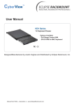
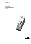
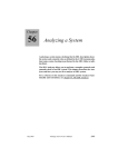
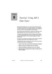
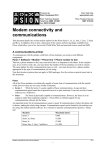
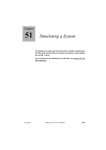
Chapter
10
Tutorial: Threaded
Integration
The Threaded Integration model provides a powerful template for
integrating generated C code with an operating system. In this tutorial, you will practice building applications using this model. You
will get hands-on experience by building the SDL system “Mobile”,
which is an implementation of a small GSM system.
This tutorial requires basic knowledge of the SDL suite editors, the
Organizer and the Targeting Expert. Brief knowledge of SDL and
integration with operating systems will also help your understanding. Before working with this tutorial, it is recommended that you
read through chapter 65, Integration with Operating Systems.
To get the most out of this tutorial, read the entire chapter. As you
progress, perform the exercises on your computer as described.
July 2003
Telelogic Tau 4.5 SDL Suite Getting Started
gs-s1
343
Chapter
10
Tutorial: Threaded Integration
Introduction
The purpose of this tutorial is to make you familiar with the Threaded
Integration model. After reading the tutorial, you should have a basic
understanding of how to build a “threaded” executable and how to integrate it with external code.
This tutorial is designed as a guided tour through the build tools in the
SDL suite. You will get acquainted with the Deployment Editor and the
Targeting Expert.
Note: Platform differences
This tutorial, and the others that are possible to run on both the Solaris and Windows platforms, are described in a way common to
both platforms. In case there are differences between the platforms,
this is indicated by texts like “on Solaris”, “Windows only”, etc.
When such platform indicators are found, please pay attention only
to the instructions for the platform you are running on.
Normally, screen shots will only be shown for one of the platforms,
provided they contain the same information for both platforms. This
means that the layout and appearance of screen shots may differ
slightly from what you see when running the SDL suite in your environment. Only if a screen shot differs in an important aspect between the platforms will two separate screen shots be shown.
Prerequisites
Windows
•
C compiler
•
Resource compiler
Solaris
344
gs-s1
•
C compiler
•
Motif (Library for GUI widgets) version 1.2 or later
Telelogic Tau 4.5 SDL Suite Getting Started
July 2003
Description of Example System
Description of Example System
The SDL System
Functional Description
The example system is a model of a GSM system. The implementation
is restricted to the high-level layers of the GSM standard. The following
functionality is implemented:
•
User PIN code verification (PIN code is one digit only)
•
Tracking of mobile phones through VLR and HLR databases
•
Freedom of movement for mobile phones by base station switching
•
Control of the IMEI code of a mobile phone
•
Billing service to keep track of elapsed time and cost for phone calls
Implementation Description
The system is implemented in a modular way. Each functional entity is
implemented as a block type. The block types are organized in a package, called “GSM”.
The SDL system uses the GSM package and instantiates its block types.
The “Mobile” system has four MobileStation block instances, four
BaseTransceiverStation block instances and two MobileSwitchingCenter block instances. The MobileStation instances are named as mobile phone owners. The names are Marie, John, ParisPizza and LyonPizza. The BaseTransceiverStation instances are named Lyon11,
Lyon12, Paris11 and Paris12, indicating their location.
The Target Application
Deployment
The Mobile system is partitioned into five executable files. Each MobileStation block instance is built as an executable and the remaining
block instances (Proxy, BaseTranscieverStation, BaseStationController, MobileSwitchingCenter and Database) execute together in one executable.
July 2003
Telelogic Tau 4.5 SDL Suite Getting Started
gs-s1
345
Chapter
10
Tutorial: Threaded Integration
The Graphical User Interface
A graphical user interface (GUI) is provided for the MobileStation
block. It is delivered as C source code to be compiled and linked when
building each of the four mobile phone executable files. The interface
resembles that of a typical mobile phone. A simple menu system, containing a phone book and a billing report, is provided. The user can
switch base station from the option menu in the bottom of the window.
The GUI is shown in Figure 212.
Figure 212: The Mobile Phone GUI
TCP/IP Communication
The executable files of the target application communicate by sending
signals via TCP/IP. The communication is handled by the SDL suite
TCP/IP communication module, which is delivered as C source code. It
is compiled and linked into each of the executables.
To be able to locate the receiver of a signal, the TCP/IP module needs
the host name and TCP port number of the receiving executable. This
information must be supplied through a routing function, which is manually implemented in C.
The mobile system is delivered with default routing functions. This will
enable you to run all executables on your computer without giving any
routing information manually.
Figure 213 shows a UML component diagram of the executable files in
the deployed mobile system. Each executable file sets up a TCP/IP server, listening on a specific TCP port number. This number is used by re-
346
gs-s1
Telelogic Tau 4.5 SDL Suite Getting Started
July 2003
Description of Example System
mote executables for addressing SDL signals. The TCP/IP server is illustrated by the interface on each component. The dashed arrows indicate a flow of signals from one component to another.
Figure 213: A Component Diagram Showing the Deployed Mobile System
July 2003
Telelogic Tau 4.5 SDL Suite Getting Started
gs-s1
347
Chapter
10
Tutorial: Threaded Integration
Preparations
Copy the Example System
In order to allow experimentation, you should copy the example system
from the SDL suite installation into a working directory of your preference:
UNIX
Copy all files from the directory
$telelogic/sdt/examples/mobile
to a working directory, e.g. ~/mobile.
Windows
Copy all files from the directory
C:\Telelogic\SDL_TTCN_Suite4.5\sdt\examples\mobile
to a working directory, e.g.
C:\Telelogic\SDL_TTCN_Suite4.5\work\mobile.
Open the System
Open the system file Mobile.sdt from the Organizer.
348
gs-s1
Telelogic Tau 4.5 SDL Suite Getting Started
July 2003
Drawing a Deployment Diagram
Drawing a Deployment Diagram
In order to build a threaded executable, you must supply information
about the threads of the application. For each thread, you must specify
which SDL instance sets that should run inside it. Finally, you may want
to partition your SDL system into several executable files.
This information is modeled using Deployment Diagrams. These are
edited using the Deployment Editor. The Deployment Diagram provides a way to model deployment of SDL systems independently of the
target platform.
What You Will Learn
•
•
To start the Deployment Editor
To deploy an SDL system onto executable files and threads
Starting the Deployment Editor
•
Double-click the deployment symbol “network_depl” in the Organizer. The Deployment Editor is launched with the selected diagram.
Deploying an SDL System
The Deployment Diagram features:
July 2003
•
Partitioning of SDL systems
•
Organization of SDL instance sets within executable files
•
Organization of SDL instance sets within threads (Threaded Integration only)
Telelogic Tau 4.5 SDL Suite Getting Started
gs-s1
349
Chapter
10
Tutorial: Threaded Integration
A deployment diagram has five symbols: the node, the component, the
thread, the object and the comment symbols. Each symbol is described
in Table 1.
Table 1 Deployment Diagram Symbols
Symbol
Name
Description
Node
A computational resource, i.e. a
computer
Component
An executable file which contains
SDL instance sets
Thread
A point of execution. The symbol is
used for threaded integrations only
Object
An SDL instance set, i.e. a system,
block or process instance set
The symbols are connected using compositions. When a symbol is selected in a diagram, a handle is shown at its bottom. Click the handle to
create a composition link. Click the symbol you wish to connect to.
The name of each symbol can be edited from the diagram area. Some of
the symbols contain additional information, which is edited from the
Symbol Details dialog box.
The network_depl deployment diagram is shown in Figure 214.
350
gs-s1
Telelogic Tau 4.5 SDL Suite Getting Started
July 2003
Drawing a Deployment Diagram
Figure 214: The network_depl Deployment Diagram
The diagram shows five components, each representing an executable
file. All components are attached to one node. Each component has one
or many threads. Each thread has one or many objects attached to it, reflecting the SDL instance sets that execute inside it.
For instance, the “JohnMS” component contains one thread, “T”. The
thread has one object attached to it, called “JohnMS”. The object reflects an SDL instance set in the network SDL system. Look at the Organizer window and compare the block instance sets shown in the system with the objects in the deployment diagram.
The Symbol Details Dialog Box
The dialog box is opened in one of the following ways:
•
July 2003
Double-click a diagram symbol
Telelogic Tau 4.5 SDL Suite Getting Started
gs-s1
351
Chapter
10
•
Tutorial: Threaded Integration
Right-click a diagram symbol. Select Symbol Details... in the popup menu.
Component
Double-click the component named “John”. The symbol details dialog
box will appear. The dialog box is shown in Figure 215.
Figure 215: The Symbol Details dialog box for Component “John”
The integration model can be selected from a drop-down list in the dialog box. The selected integration model controls the code generation parameters for the executable file that is generated from the component.
Three integration models can be selected: Light, Threaded and Tight.
For the “John” component, the selected integration model is “Threaded”. The information filled in the other text boxes is not used for code
generation.
Thread
Click the thread symbol “T”. The dialog box will change its content to
reflect that of the thread. The new appearance of the dialog box is shown
in Figure 216.
Figure 216: The Symbol Details Dialog Box for Thread “T”
For a thread, four parameters can be set for performance-tuning of the
generated executable:
352
gs-s1
Telelogic Tau 4.5 SDL Suite Getting Started
July 2003
Drawing a Deployment Diagram
•
Stack Size
•
Thread Priority
•
Queue Size
•
Max Signal Size
The values of these parameters are specific to the target operating system. If no values are given, default values are used. All threads in the
network_depl deployment diagram use default values.
Object
Click the object symbol “JohnMS”. The dialog box will change its content to reflect that of the object. The new appearance of the dialog box
is shown in Figure 217.
Figure 217: The Symbol Details Dialog Box for Object “JohnMS”
For an object, two parameters are mandatory to fill in:
•
Stereotype
•
Qualifier
The stereotype is the type of SDL instance set. The possible values are
“system”, “block” and “process”. “JohnMS” is a block, which is reflected in the stereotype text box.
The qualifier is used to identify the SDL instance set. Locate the
“JohnMS” block in the Organizer window. The block instance set is located directly under the “network” system. This renders the qualifier
“network/johnMS”.
The network_depl diagram is complete. The next step is to build executable files from the diagram.
July 2003
Telelogic Tau 4.5 SDL Suite Getting Started
gs-s1
353
Chapter
10
Tutorial: Threaded Integration
More information on the Deployment Editor is available in chapter 41,
The Deployment Editor, in the User’s Manual.
Using the Targeting Expert
What You Will Learn
•
•
•
•
To start the Targeting Expert
To build executable files from a deployment description
To configure C code generation from the Targeting Expert GUI
To configure your compiler and linker from the Targeting Expert
GUI
Starting the Targeting Expert
The deployment diagram should be used as input to the Targeting Expert.
Right-click the network_depl diagram symbol in the Organizer and select Targeting Expert from the pop-up menu.
The deployment diagram will be analyzed. If any errors are found, the
Organizer Log pops up and shows an error message. You can locate the
error in the deployment diagram by clicking on the “Show error” button
in the Organizer Log toolbar.
The Targeting Expert is launched.
Selecting Target Platform
The initial appearance of the Targeting Expert window is shown in
Figure 218.
354
gs-s1
Telelogic Tau 4.5 SDL Suite Getting Started
July 2003
Using the Targeting Expert
Figure 218: The Targeting Expert When First Opened
The left part of the window, called Partitioning Diagram Model, shows
a filtered view of the deployment diagram. The nodes and components
are represented.
For each component, do the following:
1. Select the component in the Partitioning Diagram Model window.
2. Click the drop-down list containing “SELECT INTEGRATION”. A
menu with available integrations is opened. As the component has
“Threaded” as integration (selected in the Deployment diagram),
this is the only available selection.
3. Select the platform in the sub-menu.
July 2003
–
:LQGRZV Select Win32 Threaded (CAdvanced)
–
6RODULV Select Solaris Threaded (CAdvanced)
Telelogic Tau 4.5 SDL Suite Getting Started
gs-s1
355
Chapter
10
Tutorial: Threaded Integration
4. A dialog-box will pop up, asking if the SDL system should be automatically generated. Click Yes.
The Targeting Expert window now looks as in Figure 219.
Figure 219: Components with Selected Integration Models
Configuring C Code Generation
The Targeting Expert GUI for C code generation has four tabs. These
are SDL to C Compiler, Communication, Environment Header File and
Execution. All these tabs contain widgets for configuring the code generation for an executable.
Each of the executable files that will be built have communication
through external code. All executables use the TCP/IP communication
module and the mobile phone executables (John, Marie, ParisPizza and
LyonPizza) use a GUI. The external code is connected to the SDL system through environment functions. The generation of environment
functions must be configured manually.
356
gs-s1
Telelogic Tau 4.5 SDL Suite Getting Started
July 2003
Using the Targeting Expert
The Targeting Expert features a wizard for easy configuration of the
TCP/IP module. When activating the wizard, all the necessary environment functions will be generated by default.
The TCP/IP wizard dialog box is shown in Figure 220.
Figure 220: The TCP/IP Wizard
The TCP/IP module needs routing information to send signals to the
correct recipient. A C header file with the routing function declaration
must be included. The routing function definition must be given in a C
source file. The TCP port number for incoming signals must also be given. This number is used by routing functions in remote executables
sending signals to this executable.
For each of the components, do the following:
1. Click the name of the integration in the left sub-window.
–
:LQGRZV Click Win32 Threaded
–
6RODULV Click Solaris Threaded
2. Select the Communication tab.
3. Click in the TCP/IP check box in the Signal Sending group. The
TCP/IP Wizard is opened.
4. Click in the check box Include routing header file.
5. Click the file button to the right of the header file text box. A file
selection dialog box is opened.
July 2003
Telelogic Tau 4.5 SDL Suite Getting Started
gs-s1
357
Chapter
10
Tutorial: Threaded Integration
6. Select the routing header file in your working directory.
–
If you build the John, Marie, ParisPizza or LyonPizza executable, select router.h.
–
If you build the Switch executable, select switchrouter.h.
7. Click Open.
8. Click the file button to the right of the source file text box. A file
selection dialog box is opened.
9. Select the routing source file in your working directory.
–
If you build the John, Marie, ParisPizza or LyonPizza executable, select router.c.
–
If you build the Switch executable, select switchrouter.c.
10. Click Open.
11. Enter the server port number of the executable you are building. Enter a port number according to Table 2.
Table 2 TCP Server Port Numbers for the Executables
Executable
TCP Port Number
Marie
4949
John
5959
ParisPizza
7979
LyonPizza
8989
Switch
6969
12. Click OK in the TCP/IP wizard dialog box.
The code generation configuration is now finished.
358
gs-s1
Telelogic Tau 4.5 SDL Suite Getting Started
July 2003
Using the Targeting Expert
Compiling and Linking
The Targeting Expert Compiler/Linker/Make section contains six tabs:
Compiler, Source Files, Additional Compiler, Linker, Library Manager
and Make. The section is shown in Figure 221.
Figure 221: The Targeting Expert Compiler/Linker/Make Section
July 2003
Telelogic Tau 4.5 SDL Suite Getting Started
gs-s1
359
Chapter
10
Tutorial: Threaded Integration
Compiling and Linking the Switch Executable
To configure the compilation and linking of the Switch executable, do
the following:
1. Click Compiler/Linker/Make for Switch in the Partitioning diagram
Model window.
2. In the Include text box, add -I../../../../../ After the addition, the text
box will look as shown in Figure 222.
Figure 222: The Include Text Box with an Additional -I flag
3. Click the Save button.
4. Click Target Library for Switch in the Partitioning diagram Model
window.
5. In the Kernel tab, click in the following check boxes:
–
Show errors on stdout. Setting this option renders log messages
if errors are encountered during execution.
–
Text trace. Setting this option renders textual traces on stdout
during execution.
6. Click the Save button.
7. Click the Full Make button. The SDL system is analyzed, code is
generated and a makefile is generated and executed.
You will now have an executable file named switch. The file extension
will be .exe on Windows and .sct on Solaris.
Compiling and Linking the MobileStations
To configure the compilation and linking of the MobileStation executables, do the following:
1. Click Compiler/Linker/Make for MobileStation in the Partitioning
Diagram Model window.
2. In the Include text box, add -I<your working directory>, e.g.
-I/home/mobile . After the addition, the text box will look as
shown in Figure 222.
360
gs-s1
Telelogic Tau 4.5 SDL Suite Getting Started
July 2003
Using the Targeting Expert
3. Add the following flags in the Library Flag text box:
–
-DXMAIN_NAME=SDL_Main
–
-DXEXTENV_INC=”<gui.h>”
–
-DMARIE, -DJOHN, -DPARISPIZZA or -DLYONPIZZA, depending
on which executable you are configuring
The XMAIN_NAME flag is used to rename the main function in the generated SDL system. A main function is provided in the GUI source code.
The SDL main function, renamed SDL_Main, will be started in a thread
from the new main function.
XEXTENV_INC is a flag for using environment code together with the
TCP/IP module. The gui.h file contains definitions of some macros in
the generated environment file.
4. Click the Source Files tab. A list of the external files to compile is
shown.
5. Click the Add button. A dialog box is shown.
6. Select gui.c in the working directory. Click Open. The file is added
to the file list.
7. :LQGRZVRQO\: The GUI must be compiled using a resource compiler.
–
Click the Additional Compiler tab.
–
Enter rc in the Compiler Name text box.
–
Enter -l 0x41d %I -fo %o %s in the Options text box.
–
Add the file gui.rc to the list of files to compile by clicking the
Add button and select gui.rc from your working directory.
–
Enter .res in the Object Extension text box.
–
Click on the Make tab.
–
Change from Microsoft nmake (using temporary response file) to Microsoft nmake in the Make tool drop
down list.
8. Click the Linker tab.
July 2003
Telelogic Tau 4.5 SDL Suite Getting Started
gs-s1
361
Chapter
10
Tutorial: Threaded Integration
9. Enter the following in the Options text box:
–
:LQGRZV Change -subsystem:console to -subsystem:windows
–
6RODULVAdd -lXm -lXt -lX11 between -lpthread and -L/usr/lib.
10. Click the Save button.
11. Click the Full Make button. The SDL system is analyzed, code is
generated and a makefile is generated and executed.
You will now have an executable file. The file extension will be .exe on
Windows and .sct on Solaris.
The Target System
The generated executable files are located in a directory structure created by the Targeting Expert. The Targeting Expert uses the target directory given in the Organizer as root.
In the mobile system, target is given as target directory. The generated
target directory structure is shown in Figure 223.
Figure 223: The Generated Target Directory Structure
The executable files are located in the platform-specific directories
(Win32_threaded and Solaris_threaded, respectively). The object files
are located in subdirectories of the platform directories.
362
gs-s1
Telelogic Tau 4.5 SDL Suite Getting Started
July 2003
Running the System
Running the System
What You Will Learn
•
•
To run the executable files generated from Targeting Expert
Use the mobile system
An Overview of the System
Figure 224 shows the run-time architecture of a MobileStation executable.
Figure 224: Run-time architecture of a MobileStation Executable
The SDL system interacts with the outside world through its environment. The GUI message loop is run in a thread of execution of its own.
The TCP/IP server thread executes the same way. The environment
threads interact with the SDL system by inserting signals. This is done
by calling the SDL kernel function SDL_Output.
When a signal is sent from the SDL system to the environment, it is interpreted either as GUI feedback or is sent to an external receiver via
TCP/IP.
July 2003
Telelogic Tau 4.5 SDL Suite Getting Started
gs-s1
363
Chapter
10
Tutorial: Threaded Integration
Using the System
Start the mobile system in the following order:
1. Start the Marie, John, ParisPizza and LyonPizza executables. A
GUI will pop up for each of them.
2. Start the Switch executable. Switch will initialize the MobileStation
executables by sending signals. You will see that the On buttons on
the mobile phone windows become enabled.
To make a call, do the following:
1. Click the On button on the MobileStations. You will be prompted to
enter a PIN code. The correct PIN codes are shown in Table 3.
Table 3 MobileStation PIN Codes
Executable
PIN Code
Marie
1
John
2
ParisPizza
3
LyonPizza
4
2. Click OK. “PIN OK” will be displayed. You are now ready to make
a call.
3. Click OK. The menu system of the GUI is activated. Select “Phone
Book” by pressing the “<“ and “>” buttons and click OK.
4. Select a name from the list and click OK. If the receiving MobileStation is on, its display will show “Incoming Call”.
5. Click OK on the receiving MobileStation. A call is established.
6. Click OK on the calling party and the receiving party when you
wish to finish the conversation.
The system has more features not described in this manual. Experiment
to discover its secrets!
The tutorial is finished. To get more detailed information about the
Threaded integration and the TCP/IP module, please read chapter 65,
Integration with Operating Systems, in the User’s Manual.
364
gs-s1
Telelogic Tau 4.5 SDL Suite Getting Started
July 2003