1
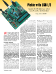
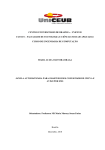
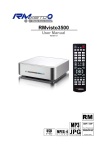
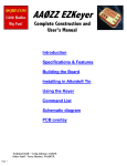
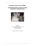
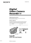
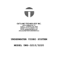
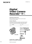
AAØZZ Si570 Daughtercard
and PIC Software
A Signal Generator for 10 to 157 MHz
By Craig Johnson, AAØZZ
AAØ[email protected]
www.cbjohn.com/AAØZZ
TABLE OF CONTENTS
Introduction ..............................................................................................................................................2
Hardware Description ...............................................................................................................................2
2.1
Circuit Description ...........................................................................................................................2
2.2
Daughtercard with PIC-EL Board ....................................................................................................3
2.3
Daughtercard In Stand-alone Board .................................................................................................3
3
Si570 Daughtercard Assembly .................................................................................................................3
3.1
Parts Identification............................................................................................................................3
3.2
Assembly ..........................................................................................................................................3
4
PEgen570 Software Application ..............................................................................................................4
4.1
A 16F88 PIC .....................................................................................................................................5
4.2
Band Tables ......................................................................................................................................5
4.3
Si570 Calibration ..............................................................................................................................6
4.4
User Interface ...................................................................................................................................6
4.5
Menu .................................................................................................................................................6
4.5.1 Sideband Selection .......................................................................................................................7
4.5.2 CW Sidetone During Receive ......................................................................................................7
4.5.3 Frequency Division for LCD Display ..........................................................................................7
4.5.4 FSK Frequency Shift ....................................................................................................................7
4.6
LCD Display .....................................................................................................................................8
Appendix A – Schematic ..................................................................................................................................9
Appendix B – Parts List .................................................................................................................................10
1
2
AA0ZZ Si570 Daughtercard v1.6 July 12, 2011
-1-
Copyright 2011 AA0ZZ
Appendix C – Si570 Daughtercard Parts Placement ......................................................................................11
Appendix D – Si570 Daughtercard PC Board ................................................................................................12
1
Introduction
This Daughtercard uses the Silicon Labs Si570 DSPLL and software to generate RF signals in the
continuous range of 10 to 157 MHz. Since many amateurs use divide-by-four mechanisms in Quadrature
Sampling Detectors (QSD) – i.e, “Tayloe” mixers - for their receivers and also in Quadrature Sampling
Exciters (QSE) for their transmitters, the Si570 Daughtercard can provide the local oscillator signal for
receivers and transmitters which operate on the 80 through 10 meter amateur bands.
2 Hardware Description
The Si570 DSPLL programmable frequency synthesizer is a relatively new technology developed by
Silicon Labs. The Si570 offers some advantages over the DDS parts that have been used in applications in
the past years. Two advantages are greatly reduced power consumption and the clean output without DDS
byproducts (spurs).
Silicon Labs offers several versions of the Si570 with different output options and frequency limits. The
version used in the Daughtercard is a CMOS part with a 10.0 MHz default frequency and a 160 MHz
maximum frequency. (The upper limit implemented in the PEgen570 application is 157 MHz.) The
internal crystal of the Si570 runs at a nominal 114.28 MHz. However, the crystal in any individual part
will not oscillate at exactly this nominal frequency. Since the the crystal frequency is used in the frequency
parameter calculations in the software, the deviation from nominal means that the frequency the Si570
generates will not be accurate. Fortunately Silicon Labs calibrates each individual part and saves the
parameters in its nonvolatile memory to cause it to start up at the default frequency (in this case, 10.0
MHz). The software can retrieve the parameters from the nonvolatile memory and calculate the calibrated
crystal frequency. This actual crystal frequency can be used in subsequent calculations and the results will
much more accurate than it would be if the nominal crystal frequency was used.
The Daughtercard can be used in a platform of your choice but here are a couple of examples.
2.1
Circuit Description
The schematic is shown in Appendix A.
Since the PIC runs at 5v and the Si570 runs at 3.3v, signal level translation circuitry is necessary. Much of
the circuitry on the board exists to do this translation. At first the problem seems trivial to solve but, since
it must be bi-directional, it is not quite that easy. At first glance the circuit is quite elegant in its simplicity
but when it is looked at closely it is a little more complicated. The design is not original to me but is
described in many I2C specifications.
The Daughtercard has two voltage regulators. One converts 12v to 5v and the other converts 5v to 3.3v.
Why not just bring 5v from the PIC-EL? Two voltage regulators are used because the PIC-EL header is
connected to 12v for the DDS-60 and I didn’t want to rewire the PIC-EL for the new Daughtercard.
The Daughtercard has two RF output paths from the SI570 to the headers even though the CMOS version
of the Si570 which we use for the Daughtercard only has one output (CLK+ on HDR3). The second RF
path (CLK- on HDR4) is there in case a different version of the Si570 is used in the future. The CLK+
signal is also routed to the 8-pin connector (HDR1) so the PIC-EL’s RF jack is usable.
AA0ZZ Si570 Daughtercard v1.6 July 12, 2011
-2-
Copyright 2011 AA0ZZ
Other versions of the Si570 have higher frequency limits but with reduced amplitude output. The spec
sheet for the CMOS version says it operates between 10 to 160 MHz but some users report it can be used
between 3.5 and 240 MHz. (The upper limit implemented in the PEgen570 application is 157 MHz.)
Header HDR2 is a 2x2 connector block that is not used when the Daughtercard is used in a PIC-EL.
However, when the Daughtercard is used in a different platform, two jumpers can be installed in this header
block (1 to 2 and 3 to 4) to route the I2C communications through the 8-pin interface connector. This
eliminates the need for the external wires from the stereo jack to the platform.
2.2
Daughtercard with PIC-EL Board
One platform for the Daughtercard is the AAØZZ PIC-EL board. (The PIC-EL board is available from
Kanga at www.kangaus.com . See details on my web page also.) An AAØZZ Signal Generator sample
application for the PIC-EL is available so it is very convenient if you want to experiment with the software.
The Si570 Daughtercard was designed to fit into a socket on the PIC-EL board that was originally designed
to accommodate a DDS-30 or DDS-60 Daughtercard from AmQRP. The DDS Daughtercard operates with
three control lines. The Si570 Daughtercard is simpler in that it operates with two communications lines.
However, the communications scheme used by the S570 is I2C and that means the lines are both bidirectional. This presents a problem for the PIC-EL since two of the three PIC lines that go to the
Daughtercard interface are also shared by the LCD and the other line is shared with the programmer. This
sharing of pins prevents two-way communications via I2C with these lines. The workaround is to use an
external cable to connect the daughtercard to the PIC-EL’s paddle jack. The paddle jack connects to
different PIC pins and these pins are only shared with PIC-EL Pushbuttons 2 and 3. These two
pushbuttons cannot be used when operating the Si570 daughtercard but otherwise the lines work well for
I2C communications.
2.3
Daughtercard In Stand-alone Board
See Control Board manual.
3
Si570 Daughtercard Assembly
3.1 Parts Identification
The builder should first identify all the parts in the kit. The parts are listed and described in Appendix B.
Every effort is made to include all parts in the kit; however, mistakes do happen. If you are missing a part,
notify Bill Kelsey at Kanga and he will send the missing parts to you. It may be faster to get common
components from your own “junk box” or at your local Radio Shack store.
3.2 Assembly
The silk-screen part names on the board will be your guide. The order in which you place the parts is not
critical but I would suggest that you install the MOSFETs last for static-protection reasons.
Here is a possible assembly order that works well if you have a PIC-EL board.
1. Install the two voltage regulators, U1 and U2. Be sure you distinguish them properly and install
them in the correct locations!
2. Install the resistors and the capacitors.
3. Install the header connectors HDR1 and HDR2.
4. Test the voltages coming out of the voltage regulators.
AA0ZZ Si570 Daughtercard v1.6 July 12, 2011
-3-
Copyright 2011 AA0ZZ
a) Plug into PIC-EL board and power up.
b) Use a Volt meter to check:
o 12v coming into HDR1 pin 8.
o 5v out of U1. Check at point where regulator connects to C3.
o 3.3v out of U2. Check at point where regulator connects to C5.
o IF ANY OF THESE VOLTAGES ARE NOT CORRECT, YOU MUST RESOLVE
THE PROBLEM BEFORE PROCEDING!
5. Install the Si570. Be sure to align the “dot” on the Si570 with the “1” on the PCB. Center the
Si570 on the pads and apply a small amount of solder to one pad and Si570 connection point. Then,
before soldering the other connection points, check the alignment of all 8 connection points on the
pads. Reheat and reposition the Si570 on the pads if necessary. Then solder the remaining 7
connection points. There three connection points on each side and one on each end.
6. Install MOSFETs Q1 and Q2. Orient per the silkscreen markings on the PCB.
7. Install the stereo phone jack, J1.
8. Construct the jumper assembly with 2 or 3 wires. One from tip-to-tip and the other from ring-toring. A ground connection wire is optional.
9. Plug Daughtercard into PIC-EL board.
10. (Optional) Software is not necessary for Si570 to generate RF at the Si570 default frequency of 10.0
MHz. If you have a frequency counter or a receiver that can tune to 10.0 MHz, power up the PICEL and verify that you have an RF output signal at 10.0 MHz. If not, stop here and find problem
before installing the PIC. If you don’t have a PIC-EL board, apply 12 volts to HDR1 pin 8, ground
to the HDR1 pin 5, and look for the 10.0 MHz output on HDR1 pin 6.
11. Plug one stereo plug of jumper cable into the J1 of Daughtercard and the other jumper cable stereo
plug into the “Paddles” jack of the PIC-EL board (J3).
12. Put the 16F88 PIC in 18-pin PIC socket of PIC-EL.
13. Program the 16F88 per PIC-EL instruction manual.
14. Switch the PIC-EL board PGM <-> RUN switch to RUN.
15. If you are using the AAØZZ Si570 Signal Generator software you MUST REMOVE THE 12v
POWER FROM THE PIC-EL BOARD AND THEN RESTORE THE POWER AGAIN! This is
important since it reinitializes and restarts the PIC program after programming. NOTE THAT THE
PIC-EL RESET BUTTON DOES NOT START THE PIC PROGRAM since the Signal Generator
program configures the PIC to use the PIC-EL RESET button as a functioning pushbutton instead of
as a PIC RESET. The Signal Generator needs this button since two of the other three pushbuttons
co-opted for use by the I2C communications via the “Paddles” connection.
4 PEgen570 Software Application
My sample application software for the AAØZZ Si570 Daughtercard is called PEgen570. It runs on a
simple, inexpensive 16F88 PIC in the PIC-EL board.
As explained in Section 2.2, the daughtercard uses an external cable to communicate with the PIC-EL
board.
AA0ZZ Si570 Daughtercard v1.6 July 12, 2011
-4-
Copyright 2011 AA0ZZ
4.1 A 16F88 PIC
There are several reasons why the 16F88 is used for this application instead of the PIC-EL standard
16F628A:
1) Compared to the 16F628A, the 16F88 has more than twice as much FLASH memory (for program
instructions), 50% more data memory (for variable storage and tables) and twice as much EEPROM
memory (non-volatile storage).
2) The 16F88 has an 8 MHz internal oscillator while the 16F628A has a 4 MHz internal oscillator. The
extra speed is nice.
4.2 Band Tables
The software is implemented to use 24 frequency bands. Most of the parameters that the Si570 requires to
produce the desired output RF signal are in tables in program memory. The program memory tables cannot
be modified with program instructions. These tables are used by the application with the band number as
an index.
One table is located in the PIC’s data memory and can be modified. This table is loaded from EEPROM
upon power-up. This table consists of 24 entries with each entry containing a starting frequency requiring
4 bytes. This means that the 24-band table requires 96 bytes of memory. Since the maximum size of any
single bank of data memory in the 16F88 (or any “16F” PIC for that matter) is 96 bytes. This determines
the maximum number of bands that can easily be handled in the PIC. With additional overhead the size
could be expanded and then the upper frequency could be increased. However, the CMOS version of the
Si570 (the version that the Daughtercard is designed to use) has a maximum frequency of 160 MHz. This
means the current 96-byte table with an upper limit of 157 MHz is sufficient for this Si570 version. The
lower limit of the Si570 is 10 MHz and the 96-byte table also handles this limit.
The 24 PEgen570 bands were created by examining the Si570 spec sheet and making calculations with a
spreadsheet based on the Si570 parameter requirements. Without getting into the esoteric requirements of
the Si570 frequency generating parameters and the formula involving several specific “multipliers”, the
Si570 internal crystal frequency and the desired output frequency, the frequency range of each band was
calculated. The table was generated in such a way that the major parameters for each band can be precalculated and retrieved from tables when changing frequency. This greatly minimizes the number of
complex calculations that must be done for each frequency change.
The 24 PEgen570 bands are defined as follows:
BAND
Frequency
Range
BAND
Frequency
Range
BAND
Frequency
Range
BAND
Frequency
Range
0
10 - 11 MHz
6
19 - 21 MHz
12
36 - 41 MHz
18
81 - 90 MHz
1
11 - 12 MHz
7
21 - 23 MHz
13
41 - 47 MHz
19
90 - 101 MHz
2
12 - 13 MHz
8
23 - 15 MHz
14
47 - 54 MHz
20
101 - 111
MHz
3
13 - 15 MHz
9
25 - 28 MHz
15
54 - 61 MHz
21
111 - 128
MHz
AA0ZZ Si570 Daughtercard v1.6 July 12, 2011
-5-
Copyright 2011 AA0ZZ
4
15 - 17 MHz
10
28 - 32 MHz
16
61 - 70 MHz
22
128 - 135
MHz
5
17 - 19 MHz
11
32 - 36 MHz
17
70 - 81 MHz
23
135 - 157
MHz
4.3 Si570 Calibration
The PIC’s Si570 band tables described in Section 4.2 are pre-calculated with the nominal value for the
Si570’s internal crystal frequency (114.285 MHz). The table entries, combining the crystal frequency with
other parameters needed to generate RF in that frequency range, are stored in the PIC’s EEPROM and are
loaded into the PIC’s volatile memory at power-up. This nominal frequency is almost never perfect, of
course, but the Si570 is calibrated in the factory to use corrected parameter values to produce the default
start-up output frequency of exactly 10.0 MHz. (Other Si570 part numbers use different start-up
frequencies.)
By holding Pushbutton 3 down during power-up, the application is directed to retrieve the parameters from
the Si570’s non-volatile EEPROM memory. The software then does a “reverse calculation” to find the
actual Si570 crystal frequency as determined by the factory to produce 10.0 MHz. After the actual crystal
frequency is determined, the table entries are recalculated and copied back to non-volatile EEPROM.
When Pushbutton 3 is released, the PIC restarts and populates the tables with the newly calculated values.
4.4 User Interface
The user interface for the PEgen570 application is very simple. It uses two pushbuttons, an encoder, and a
2- line by 16-character LCD.
The “Reset” pushbutton on the PIC-EL board is configured (via the CONFIG statement in the source code)
such that it does not perform a microprocessor reset when pressed but to operate as a normal I/O pin
instead. This made the pushbutton available for operation and it is needed. To clarify this change in usage,
the pushbutton will be referred to as Pushbutton 4 rather than the Reset pushbutton. This means that the
9PIC-EL board must be powered down and up after loading new software into the PIC before the new
program will start executing. Simply moving the slide switch from PGM position to RUN position does not
start the program.
The Pushbutton 3 and Pushbutton 4 are the two operational pushbuttons. When running the Si570, each
time Pushbutton 3 is pressed and released the tuning digit that is currently being modified by turning the
encoder to be increased by one digit. It can be advanced up to the 1 MHz position. Similarly, each time
Pushbutton 4 is pressed and released, the tuning digit that is currently being modified by turning the
encoder to be decreased by one digit. The digit that is currently being modified by the encoder is
underlined.
When the daughtercard is running, pressing and holding Pushbutton 3 for longer than 2 seconds stores the
current frequency in EEPROM. This frequency is used as the start-up frequency on subsequent power-ups.
4.5 Menu
A simple menu is used for changing 3 items in the operation.
1) Sideband selection
2) Frequency division for LCD display
AA0ZZ Si570 Daughtercard v1.6 July 12, 2011
-6-
Copyright 2011 AA0ZZ
3) FSK enable (if FSK is enabled via compile option in source code)
The menu is activated by holding Pushbutton 4 while pushing Pushbutton 3 and then releasing them both.
The current mode is shown in character position 1 of line 1 of the LCD. Now the user can update the
current selection of each of the three items. Tapping Pushbutton 3 allows the user to cycle through the
available options for the current item. Tapping Pushbutton 4 leaves the current item at its last value and
advances to the next item in the menu. After the last item has been selected, pressing Pushbutton 4 exits
the menu.
4.5.1
Sideband Selection
The first menu item that may be selected in the menu is the sideband selection. The user may select one of
four sideband modes, USB, LSB, CW+ or CW- .
An external latching relay is engaged or disengaged as the sideband is changed in the menu. PIC output
ports RA6 and RA7 attach to HDR5 and HDR6 (pins 15 and 16) respectively. As the sideband is changed
in the menu, either RA6 or RA7 is driven high with an 8 mS pulse (with the opposite side being held low)
to engage or disengage the external latching relay. The recommended latching relay (TQ2-L-5V – DigiKey
part 255-1004-5-ND) requires 14 mA at 5v for 3 mS plus contact bounce time. The latching relay is
intended to enable the proper I and Q phases of the transmitter and/or receiver to set the proper sideband.
4.5.2
CW Sidetone During Receive
If the mode is CW+ or CW- , Header HDR7, attached to PIC input port PB7, is monitored by the software
to determine whether or not to shift the frequency by the sidetone amount. HDR7 is expected to be set to a
low state by external Transmit/Receive circuitry during Receive operations and to a high state during
Transmit operations. The software continually monitors the signal at HDR7 and, when is detected to be
low while in CW- mode, shifts the frequency down by 600 Hz from the nominal, displayed frequency. If
the mode is CW+ and HDR7 is LOW (Receive), the frequency is shifted up by 600 Hz from the nominal,
displayed frequency. In either case, whenever HDR7 is detected to be HIGH, indicating Transmit
operation, the frequency will be set back to the nominal frequency that is displayed on the LCD.
How fast does it switch? The software looks at the signal on HDR7 often enough to detect and change the
frequency within 1.6 mS of HDR7 changing state. That’s fast enough for QSK.
4.5.3
Frequency Division for LCD Display
The PEgen570 application can be configured to display the current Si570 generated frequency or it can be
configured to display the Si570 frequency divided by two or four. The divide-by-four option is useful
when the signal generator is being used as a signal source for a QSD/QSE (“Tayloe”) mixer. The circuitry
for these mixers usually divides the input frequency by four so this software option allows the LCD to
display the mixer’s operating frequency.
Tapping PB3 while in this portion of the menu allows the divide-by-x factor to be changed. When the
correct factor is selected, press PB4 to advance to the next menu item selection.
4.5.4
FSK Frequency Shift
This menu item is only available and displayed only if the FSK option is enabled via a #DEFINE statement
in the source code. The default software does not have FSK enabled.
Tapping PB3 while in this portion of the menu allows the FSK option to be enabled or disabled. When the
correct factor is selected, press PB4 to advance to the next menu item selection.
AA0ZZ Si570 Daughtercard v1.6 July 12, 2011
-7-
Copyright 2011 AA0ZZ
If FSK is enabled, the FSK shift size will be used, even if CW+ or CW- is also selected in the menu. FSK
takes precedence.
When FSK is active, Header HDR7, attached to PIC input port PB7, is monitored by the software to
determine whether or not to shift the frequency by the FSK shift size. The frequency is set to the displayed
frequency when the signal on HDR7 is HIGH (the MARK frequency) and is shifted down by 170 Hz when
the signal on HDR7 is LOW (the SPACE frequency).
The software looks at the signal on HDR7 often enough to detect and change the frequency within 1.6 mS
of HDR7 changing state.
4.6 LCD Display
The first line of the LCD displays the current frequency. The second line is for debug purposes and shows
the hex digits for the 6 Si570 register parameter (SiReg7 through SiReg12) starting at LCD position 1. The
current band number is displayed in positions 15 and 16 of line 2.
As explained in the Menu section regarding the frequency division selection option, the PEgen570
application can be configured to display the current Si570 frequency or it can be configured to display the
Si570 frequency divided by two or four. The divide-by-four option is useful when the signal generator is
being used as a signal source for a QSD/QSE (“Tayloe”) mixer. The circuitry for these mixers usually
divides the input frequency by four so this software option allows the LCD to display the mixer’s operating
frequency.
AA0ZZ Si570 Daughtercard v1.6 July 12, 2011
-8-
Copyright 2011 AA0ZZ
Appendix A – Schematic
AA0ZZ Si570 Daughtercard v1.6 July 12, 2011
-9-
Copyright 2011 AA0ZZ
Appendix B – Parts List
Si570 Daughtercard
Quantity
Designator
1
HDR1
1
3
J1
for I2C
cable
C1, C4, C6,
C8
C7
C2, C3, C5
R1-R4
U3
U1
U2
Q1, Q2
HDR2
for HDR2
for I2C
cable
1
U1
2
4
1
3
4
1
1
1
2
1
2
1
Parts
Description
8-pin RA Header
Audio Jack 3.5mm
Ver 1.3
Part number
(Samtec) TSW-108-08-F-S-RA
(D) CP1-3513N-ND
(M) 161-3507-E
12/28/2010
Single
Price
$0.26
Total
Price
$0.26
$0.53
$0.53
$1.04
$2.08
Stereo plug 3.5mm Male
(D) CP-3502-ND
.1 uF ceramic cap
.001 uF ceramic cap-axial
10 uF tantalum cap
1K resistor 1/8w 5%
Si570 CMOS 20ppm 10MHz
REG LDO 1A 5.0V SOT223-3
REG LDO 1A 3.3V SOT223-3
BS-170 N-chan MOSFET
pin header, 0.1", 2x2 pos'n
shunt, 0.1", 2 pos'n
#22 Insulaed Hookup wire
(3 colors, 7" each)
(D) 478-4855-ND
(D)1116PHCT-ND
(D) 399-3638-ND
(D) 1.0KEBK-ND
Silicon Labs 570CBC000107DG
(D) ZLDO1117G50DICT-ND
(D) ZLDO1117G33DICT-ND
(D) BS170-ND
(M) 571-1032402
(D) S9000-ND
$0.19
$0.08
$0.79
$0.06
$25.06
$0.62
$0.62
$0.48
$0.32
$0.08
$0.76
$0.08
$2.37
$0.23
$25.06
$0.62
$0.62
$0.96
$0.32
$0.16
(D) A3051B-100-ND or similar
$0.10
$0.30
PIC 16F88 (programmed)
(D) PIC16F88-I/P-ND
with AA0ZZ software
$7.50
$7.50
PCB
AA0ZZ supplied
$4.00
$4.00
========
$45.85
AA0ZZ Si570 Daughtercard v1.6 July 12, 2011
- 10 -
Copyright 2011 AA0ZZ
Appendix C – Si570 Daughtercard Parts Placement
AA0ZZ Si570 Daughtercard v1.6 July 12, 2011
- 11 -
Copyright 2011 AA0ZZ
Appendix D – Si570 Daughtercard PC Board
AA0ZZ Si570 Daughtercard v1.6 July 12, 2011
- 12 -
Copyright 2011 AA0ZZ