1
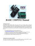
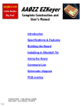
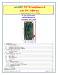
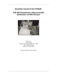
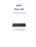
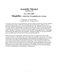
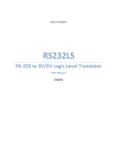
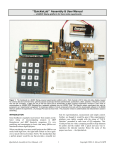
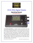
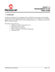
Pickle with USB I/O Update the PIC-EL to use with a new PC with a USB interface. Craig Johnson, AAØZZ several examples of simple hardware circuits using COM ports and we were quite confident that we could make similar circuitry work in our application. To develop the circuitry for a USB interface, whether it was one of the integrated circuits designed for this type of task or if the circuitry was designed from scratch, it was obvious that a USB solution would be much hat do you mean it doesn’t have more complicated. a USB interface? I don’t even Second, we didn’t have a simple PC have a COM port on my new application to drive the programmer with a computer!” Such was the cry from the very USB interface that we could use to send the beginning from many people who wanted to low level (HEX) code into the PIC. We had learn to program PIC microcontrollers and several nice, free, PC applications that could then read about the COM port based PIC-EL drive the COM port circuitry we were lookboard and the associated online PIC pro- ing at, however. gramming course that we developed. We carefully evaluated these reasons and concluded that the risks with pushing for a The PIC-EL Revisited USB interface were too great. We decided In the May and June 2007 issues of QST to go with the simple COM port for the first I presented a two part article describing the version, with the intent of continuing to look PIC-EL. This project was developed to help for a USB solution for the future. hams get practical hands-on experience using In my PIC-EL YAHOO group, users PIC microcontrollers for some fun and use- of the PIC-EL board discuss their projects ful ham applications.1 As John McDonough, and ask questions about PIC programming WB8RCR, began writing his lessons for the issues as well.3 One of the subjects that freElmer-160 course, several of us who are quently comes up is how to get the PIC-EL associated with the AmQRP club began to work with a USB interface. While we designing this companion board to allow the tried using various COM-to-USB converters students to experiment with the material as (they don’t work, since we drive the COM they navigate through the lessons.2 I decided port pins directly) I quietly kept looking for to call it the PIC-EL (“pickle”), since it’s for a good solution. PIC microcontrollers and it goes along with I investigated many different methods the Elmer-160 lessons. but each had severe drawbacks, including Right from the beginning we knew the need for me to write new programthat a USB interface would be a desirable ming software to support it. Then, in late interface for the tool. However, there were 2007, I bought a Microchip PICKit2, thinkseveral problems. First of all, we had a very ing it might be a way to quickly attach to tight, self-imposed time schedule. We really the PIC-EL with a USB connection.4 The wanted to get the board ready to go about PICKit2 would be connected such that three months from the day I hand-sketched it would bypass the PIC-EL’s hardware out the first conceptual circuit and e-mailed programmer and connect directly into it to the other team members. We then found the PIC-EL’s configuration header. My initial attempts to make this work failed, 1Notes appear on page 5. but several months later I discovered that W Microchip had published a set of updates for the PICKit2 hardware. After I installed them, it worked perfectly on the PIC-EL II. I then discovered a number of “clones” on the Internet and, upon examining them, realized that a lot of the hardware in the Microchip PICKit2 is nice but not really needed for a PIC-EL environment. I then made and prototyped a stripped down version of the PICKit2 using ideas from other designs on the Internet but putting my own spin on it. After some extended debugging sessions the PIC-EL III was born. PIC-EL III Hardware Description The schematic of the new PIC-EL III board is shown in Figure 1. The “right side,” the various hardware components that can be driven by the target PIC, has been changed very slightly since the PIC-EL II, but the “left side,” the programmer portion, has been completely replaced. PIC-EL III Computer (USB) Interface and Programmer The programmer section has been replaced with circuitry to provide a USB interface. The circuitry is a simplified version of the PICKit2 by Microchip Technology (www.microchip.com) and has a Microchip PIC 18F2550 in its center. The code for the 18F2550 is produced and distributed (free of charge) by Microchip. The PIC-EL III hardware programmer uses MOSFETs to drive the programming lines. It does not draw 5 V power from the USB connection but instead runs on 5 V power from the PIC-EL’s 12 V to 5 V regulator. The programmer hardware has charge pump circuitry to internally generate the +12 V programming voltage (VPP) to be applied to the MCLR pin. Note that the PIC-EL expects 12 V power being supplied at all times and it does not use the 5 V power supplied by the USB. The PIC-EL’s 12 V to 5 V voltage converter supplies all the 5 V power for the PIC-EL board. Note that when the PIC-EL is in February 2010 1 Figure 1 — Schematic diagram of the PIC-EL with USB interface. The right side is very similar to the previous versions. See parts list on page 6. 2 February 2010 February 2010 3 in the 2007 QST article so I won’t repeat it here. In brief, PIC experimenters using a PIC-EL have an easy way to use and understand the following hardware components: 18 pin PIC microcontroller (16F84A, 16F628/A, 16F88, 18F1320, and others) 4 MHz crystal oscillator 2 × 16 LCD (two lines of 16 characters) Rotary encoder (ENC-1) Three general-purpose push-buttons (PB1 through PB3) A dedicated push-button (PB4) for master clear (reset) of the PIC microcontroller Three LEDs (LED1 through LED3) A speaker (SPKR-1) with transistor driver. Figure 2 — Schematic of basic PIC circuit All connections necessary to mount showing interconnections. and drive an NJQRP DDS daughtercard (DDS-30 or DDS-60) A stereo jack for connection to CW PROGRAM mode, the programmer hardware paddles. A stereo jack with transistor driver for generates VDD (+5 V) and VPP (+12 V) with the appropriate timing to program the target transmitter keying A transistor “conditioner” for convertPIC. Depending on the type of PIC being programmed, the programmer sometimes ing low level signals to levels required for raises VPP before VDD and sometimes raises PIC input detection. A multi-purpose BNC connector VDD before VPP. It’s tricky but very impor Selectable via a jumper at header tant. (This removes a limitation found in the previous PIC-EL versions as well as all HDR2 Allow DDS output to be routed to the other Tait type programmers that use a COM interface. There simply aren’t enough pins in BNC A llow DDS output to be routed a COM port to do this.) through the “conditioner” circuit and then to Project/Demonstration Portion Figure 3 — Two methods of illuminating an LED. a PIC input pin Allow an outside signal source to be brought in to the “conditioner” and then to the PIC input pin A 2 × 7 pin header block (HDR1 CONFIG) Allows attachment of a foreign programmer to this PIC project board Allows attachment of this programmer to a foreign project board. The PIC-EL schematic (Figure 1) may look quite complicated because many of the The project/demonstration portion of the PIC-EL board was described in great detail Figure 4 — Schematic of control circuitry for a backlighted LCD display panel. 4 February 2010 Figure 5 — Screenshot of Microchip PICKit2 software screen. PIC pins have multiple usages. It’s much easier to understand the individual functions when they are isolated. Here are a couple of examples. Figure 2 shows the basic connections and components that are required to run any PIC. (The crystal is optional but is used in the PIC-EL.) Figure 3 shows the basic connections and components needed to light an LED, while Figure 4 shows one way of connecting an LCD. Many more examples were shown in the previous QST articles and are shown in the user manual.5 Programming a PIC with the PIC-EL III Power up the PIC-EL Connect the USB connector to the PC to the PIC-EL Start the PICKit2 application Flip the PROGRAM / RUN switch in the PIC-EL to the PROGRAM position Insert the PIC to be programmed in the PIC-EL socket Select the PIC TYPE in the pull-down box in the PICKit2 application Import the code (.HEX format) from the location on your PC where it is stored Press the WRITE tab Wait for a SUCCESS message. The verify operation is automatic. Code to be loaded into the PIC in the PIC-EL can be developed in many different Running the PIC Program ways. If you follow the lessons in the Elmer- on the PIC-EL III 160 course you will be able to understand Now you are ready to try out the PIC prothe PIC architecture and command set well gram that you just loaded into the PIC. It’s enough to write your applications in low just a matter of flipping the PROGRAM / RUN level machine language code. Hey, it’s not switch to RUN position and the PIC program that hard. There are many examples of PIC will start up. Now you can see the results of code on the Internet, and you can easily col- your labor. Fun, isn’t it? lect pieces that are useful in your application. How quick is it? I can literally change the I also have several working examples on my source code of a program, assemble it, write Web page and in the FILES section of the it into the PIC, flip the switch and try it out PIC-EL YAHOO group of code that works on in about 20 seconds! That’s why developing the PIC-EL.6,7 There are a simple CW keyer, code with a PIC-EL is so much fun. a frequency counter and a signal generator using the DDS-30 or DDS-60. The code for Options these sample applications is written in a form Microchip’s PICKit2 Application runs on that makes it easy to understand (many com- the Windows 98 SE platform and beyond. I ments) and can be used as a springboard for mentioned Microchip’s stand-alone PICKit2 your own application. All are readable with a application because it’s perhaps the easiest text editor. Go ahead and take a look. way to go. There are a few other possibilities, however. Microchip’s MPLAB IDE can also Writing the Code into the PIC be used as well as Microchip’s commandOne of the great benefits in having line interface program called PK2CMD. PICKit2 look-alike hardware is that it Microchip has versions of PK2CMD for can be driven with the neat, stand-alone Windows as well as Linux and Mac OS X. Windows application that Microchip freely distributes. Alternatively, it can be done with Questions and Support Microchip’s freely distributed MPLAB IDE For up-to-date details and documentaor their command-line version, PK2CMD. tion regarding this project, please see my Note that Microchip also has versions of Web page, www.cbjohn.com/aa0zz. For PK2CMD that run under the Linux and additional support questions, see the PIC-EL Macintosh operating systems as well.8,9 YAHOO group or e-mail the author. With the PIC powered up and the USB cable connected, the PICKit2 application can be Conclusion started. It will connect with the 18F2550 It’s very satisfying to be able to develop PIC in the PIC-EL and immediately report a PIC program that performs a task exactly that it found a PICKit2. Figure 5 is a screen- the way you want it to. Using the PIC-EL to shot showing the PICKit2 application con- develop and test code is a very convenient nected to the PIC-EL and ready to program a and enjoyable way to do this. With the low PIC. Programming a PIC is this easy: prices for PIC microcontrollers these days, it’s really easy to think of lots of ways to use them. In simple configurations, you don’t even need a crystal, so it’s easy to throw a micro into a simple circuit to accomplish a task that you have in mind. Yes, it takes a bit of effort, but the end result is well worth it. Once you get going, you will be amazed how many more applications you will dream up. Notes 1www.amqrp.org/elmer160/index.html. 2G. Heron, N2APB; J. Everhart, N2CX; J. McDonough, WB8RCR; E. Morris, N8ERO; J. Kortge, K8IQY, and the author. 3www.groups.yahoo.com/group/PIC-EL. 4Microchip Technology Inc (www.microchip. com). 5PIC-EL III kits are now available from Bill Kelsey, N8ET, at Kanga. See his Web page, www.kangaus.com for details, or e-mail him at [email protected]. 6www.cbjohn.com/aa0zz. 7See Note 3. 8www.linux.com. 9www.apple.com/mac/. ARRL member and Extra Class licensee Craig Johnson, AAØZZ, has earned BSEE and MBA degrees. He worked for Unisys for 35 years on the design and development of large computers and now works for Alliant Techsystems, a Defense Department contractor, developing microprocessor based products for the military. Craig holds seven US patents based on his work in computer hardware and software. Craig got his first ham license in 1964 at the age of 14. He credits ham radio with sparking his interest in electronics and as a major factor in pointing him toward a career in electrical engineering. During and after his college years, however, he let his license lapse for several years and concentrated on computers. For several years, Craig led a team of Volunteer Examiners (VE) and helped hundreds of people in the St Paul area get or upgrade their licenses. He still serves as a VE on occasion. He is an active member of the Minnesota QRP Society. Craig enjoys low power operating (QRP), DXing and contesting. He is happiest, however, when he is tinkering, building or experimenting with his new designs, circuits and software. His current interests are centered around projects that use microcontrollers, Direct Digital Synthesis and the new digital modes. You can reach Craig at 4745 Kent St, Shoreview, MN 55126 or at aa0zz@ arrl.net. Did you enjoy this article? Cast your vote at: www.arrl.org/members-only/ qstvote.html February 2010 5 Parts list for Figure 1 (pages 2 and 3) C1, C2, C14, C15 — 22 pF, ceramic disc (DigiKey 490-3639-ND, Mouser 140-50N2-220J-RC). C3, C4, C6, C7, C9, C10, C13 — 0.1 μF, monolithic (Digi-Key P4910-ND, Mouser 80-C317C104M5U). C5, C8 — 4.7 μF, 16 V, electrolytic (Digi-Key P996-ND, Mouser 140-XRL16V4.7-RC). C11 — 0.22 μF, monolithic (Digi-Key 445-2849-ND). C12 — 47 μF, 16 V, electrolytic (Digi-Key P969-ND). C16 — 0.47 μF, ceramic radial (Digi-Key BC1150CT-ND). D1, D4 — BAT85 (Digi-Key 568-1617-1-ND). D3 — 1N4004 (Digi-Key 1N4004-E3/73GI-ND). D6 — 1N4148 (Digi-Key 1N4148FS-ND, Mouser 625-1N4148). ENC — Rotary encoder (Digi-Key P10860-ND, or Digi-Key P12334-ND or Digi-Key P12335-ND). HDR-1 — Pin header, 0.1", 2 × 7 position (Mouser 571-4-103328-3). HDR-2 — Pin header, 0.1", 2 × 2 position (Mouser 571-1032402). HDR-3 — Pin header, 0.1", 1 × 2 position (Mouser 571-1032392). J1 — Coaxial power jack, 2.1 mm (Digi-Key CP-102AH-ND). J2 — USB B receptacle (Digi-Key WM17131-ND). J3, J8 — Audio jack, 1⁄8", stereo (Digi-Key CP1-3513N-ND, Mouser 161-3507-E). J4 — SIP header, 16 position (LCD) (Mouser 571-16404526). J5 — DIP socket, 18 position (PIC) (Digi-Key ED3118-ND). J6 — SIP socket, 8 position, 90° (SamTec SSQ-108-04-T-S-RA). J7 — BNC jack, PCB mount (Mouser 523-31-5538-10-RFX). J9 — DIP socket, 28 position (PIC) (Digi-Key ED3128-ND). L1 — 680 μH inductor (Digi-Key M8156-ND). LCD — Liquid crystal display, 2 × 16 character (ElectronixExpress.com 08LCD9). LED1-LED4 — LED, T1-3⁄4 (red) (Digi-Key 67-1110-ND). LED5 — LED, T1-3⁄4 (green) (Digi-Key 67-1109-ND). P4 — SIP socket, 16 position (PCB) (Digi-Key ED7150-ND, Mouser 517-974-01-16). PB1, PB2, PB3, PB4 — SPST push-button, momentary (Digi-Key P8079SCT-ND). Q1, Q2, Q4 — BS170, TO-92 (Digi-Key BS170-ND). Q3 — BS250, TO-92, with two sides flat (Digi-Key BS250P-ND). 6 February 2010 Q5, Q7 — 2N3904 transistor, NPN, TO-92 (Digi-Key 2N3904D26ZCT-ND ). Q6 — 2N4401 transistor, NPN, TO-92 (Digi-Key 2N4401-ND, Mouser 610-2N4401). Q8, Q9 — IRF9Z24, TO-220 (Digi-Key IRF9Z24PBF-ND). R1 — 75 Ω, 1⁄4 W (Digi-Key 75EBK-ND). R2, R9, R10, R21-R26, R30, R34, R36, R38 — 10 kΩ, 1⁄4 W (Digi-Key 10KEBK-ND, Mouser 291-10K-RC). R3, R8, R27, R29 — 4.7 kΩ, 1⁄4 W (Digi-Key 4.7KEBK-ND). R4 — 2.7 kΩ, 1⁄4 W (Digi-Key 2.7KEBK-ND). R5, R6 — 47 Ω, 1⁄4 W (Digi-Key 47EBK-ND). R7, R11, R12, R16-R18, R20 — 1 kΩ, 1⁄4 W (Digi-Key 1.0KEBK-ND, Mouser 291-1K-RC). R13, R15 — 470 Ω, 1⁄4 W (Digi-Key 470EBK-ND, Mouser 291-470-RC). R14 — 5.6 kΩ, 1⁄4 W (Digi-Key 5.6KEBK-ND, Mouser 291-5.6K-RC). R19 — 6.8 kΩ, 1⁄4 W (Digi-Key 6.8KEBK-ND, Mouser 291-6.8K-RC). R28, R31, R35 — 100 Ω, 1⁄4 W (Digi-Key 100EBK-ND, Mouser 291-100-RC). R32 — 100 kΩ, 1⁄4 W (Digi-Key 100KEBK-ND, Mouser 291-100K-RC). R33 — 51 Ω, 1⁄4 W (Digi-Key 51EBK-ND, Mouser 291-51-RC). R37 — 6.2 Ω, 1⁄4 W (Digi-Key 6.2EBK-ND, Mouser 291-6.2-RC). S1 — Slide switch, DPDT (Digi-Key SW102-ND). Shunts for HDR1-HDR3 — shunt, 0.1", 2 position (Digi-Key S9000-ND, Mouser 571-2-382811-1). SPKR — Speaker (Digi-Key 433-1028-ND). U1 — PIC16F628A microcontroller with diagnostics pre-loaded (Mouser 579-PIC16F628A-E/P with AAØZZ diagnostics). U2 — L7805 voltage regulator, 5 V, TO-220 (Digi-Key 497-1443-5-ND, Mouser 511-L7805 ABV). U3 — PIC18F2550 microcontroller with PICKIT2 code pre-loaded (Digi-Key PIC18F2550-I/SP-ND with code). XTAL1 — Crystal, 4 MHz (Digi-Key X405-ND, Mouser 520-HCU400-20). XTAL2 — Crystal, 20 MHz (Digi-Key CTX416-ND).